Rochester Institute of Technology
RIT Scholar Works
Theses
Thesis/Dissertation Collections
2006
Dynamic Object Tracking by Partial Shape
Matching for Video Surveillance Applications
Mustafa Husain
Follow this and additional works at:
http://scholarworks.rit.edu/theses
Recommended Citation
DYNAMIC OBJECT TRACKING BY PARTIAL
SHAPE
MATCHING FOR
VIDEO SURVEILLANCE
APPLICATIONS
By
Mustafa Husain
A Thesis submitted
in Partial
Fulfillment of
the
Requirements for the Degree
of
MASTERS
OF
SCIENCE
In
Electrical Engineering
Approved
by:
Professor
Eli
Saber
(Dr Eli Saber - Advisor)Professor
Sohail A. Dianat
(Dr. Sohail A. Dianat -Comminee Member)Professor
Daniel B. Phillips
(Dr. Daniel B. P~illips -Committee Member)Professor
Vincent Amuso
(Dr. Vincenl Amuso -Department Head)DEPARTMENT
OF ELECTRICAL ENGINEERING
COLLEGE OF ENGINEERING
ROCHSTER
INSTITUTE OF TECHNOLOGY
ROCHESTER, NEW YORK
THESIS RELEASE
PERMISSION
DEPARTMENT
OF ELECTRICAL ENGINEERING
COLLEGE OF ENGINEERING
ROCHESTER
INSTITUTE OF TECHNOLOGY
ROCHESTER
,
NEW YORK
Title of Thesis:
DYNAMIC OBJECT TRACKING BY PARTIAL SHAPE
MATCHING FOR VIDEO SURVEILLANCE APPLICATIONS
I
,
Mustafa
Husain
,
hereby
grant perrmsslOn to Wallace Memorial Library of
the
Rochester Institute
of Technology
to
reproduce my thesis
in
whole or in part
.
Any
reproduction
will not be for commercial
use
or profit.
ACKNOWLEDGEMENTS
First I mustthankDr. Eli Saber. Not onlybecause hetaughtme everythingthatIknowin digital video processing but more
importantly
because he taught me how to research. Iwould like to thank Dr. Daniel B.
Phillips,
Dr. Sohail A. Dianat and Dr. Vladmir Misicfor
taking
time out oftheirbusy
schedule and going through my thesis, providing theirvaluable insightsand constructive criticism.
I would also like to thank the Center for Electronic
Imaging
Systems-a NYSTAR
designated Center for Advanced
Technology,
PLECommunications,
LLC and theElectrical
Engineering
Department of the Rochester Institute ofTechnology
forABSTRACT
Inthisthesis, an algorithm forobject
tracking
through frames of video usingafastpartialshape matching technique is proposed. The
tracking
is divided into two modules:1)
moving object extraction followed
by
color/edge segmentation, and2)
tracking
throughframes using partial shape matching. The major challenges of object tracking, such as
occlusions, splitting of one object and appearance and disappearance of objects, are
effectively resolved. The proposed algorithm is tested on several synthetic and real life
video sequences and is shown to be very effective in
identifying
andtracking
movingobjects independentoftranslations,rotations, scale variationsand occlusions.
The novelty ofthe proposed algorithm lies in its ability to
independently
track full andpartial objects undergoing split, merge and occlusion scenarios independent of their
location and scale in the scene. . The technique assumes that:
1)
the video frames arecaptured at 30 frames per second in order forthe object(s) motion
(translation,
rotation,isometric scale variations) to be well modeled
by
an affine transformation,2)
theobject(s)
being
tracked are larger than a certain number of pixels to allow forTable
ofContents
Acknowledgements
1Abstract
2Table of
Contents
3
ListofFigures 4
List ofTables
5
Chapter 1
6
1.
Introduction6
Chapter 2
102.
Background
10Chapter 3
163.
Object
Tracking
Algorithm 163.1 Lowlevel Frame Analysis 17
3.2
Tracking
Algorithm 203.2.1 Case I (objectcontinuity) 24
3.2.2 Case II (Object
Merge/Exit)
243.2.3 Case III (Object Split/
Entrance)
253.2.4 Computational Aspectsofthe
Tracking
Algorithm 25Chapter 4
264. Experimental Results and
Discussions
26Chapter 5
39
5.
Conclusions and Future Work 39Appendix I - RGB to HSV Transformation
42
Appendix II - HausdorffDistance
for
Comparing
Images
43List
ofFigures
Figure 1: Block diagramofthe utilizedpartial shapematching procedure 1 1
Figure 2: Definitionofhighcurvature points 12
Figure 3: Block diagram ofthe proposedhybrid
tracking
algorithm 17Figure 4: Flowchart for low level frameanalysis 18
Figure 5: Flowchartofthe
Tracking
Algorithm 22Figure 6: Visual illustration for matchingalgorithm:
(a)
Typical movingobject,(b)
Segmentationmap,
(c) Adjacency
matrix,(d)-(g)
Combinationofsuccessfullymatched elementaryregions and
(h)
the largest matchHistory
23Figure 7:
Tracking
resultsfor"Lab sequence(a)-(f)representframes18,
59,79,
92,
109,
and 152 (Redoutline aroundthe objectindicatesresult oftracking
algorithm) 27
Figure8: Objecttrajectoryfor Lab simulatedScene. The horizontal and vertical axes of
thegraphs representthewidth andtheheight oftheframe respectively 28
Figure9:
Tracking
resultsfor'"RITParking
lot"
sequence
(a)-(f)
representframes2, 11,
25,
37,44,
and56 (Pinkoutline aroundtheobjectindicates result oftrackingalgorithm) 29
Figure 10: Object trajectoryfor RIT parking Lot Sequence 30
Figure 11:
Tracking
results for"toy
sequence(a)-(f)representframes8, 20,
26, 30,33,
and 38 (Yellowand pink outline aroundthe objectsindicatesresultoftrackingalgorithm) 31
Figure 12: Objecttrajectoryfor"ToyCar" Sequence 32
Figure 13:
Tracking
resultsfor"RITjunction"
sequence
(a)-(b)
frames25,
26(c)-(d)
frames 29. 30 (e)frame 32
(f)-(h)
frames 34. 35.37 and(i)
frame 38(Yellow andpink outline aroundthe objects indicatesresult of
tracking
algorithm) 33Figure 14: Object trajectories (frames20to
38)
for RIT Junction Sequence 34Figure 15:
Tracking
results for"Parking
Lot"sequence
(a)-(i)
representframes
4. 24.36,
Figure 18: Object
Tracking
andRecognition using Multiple Multimodal Sensors 40Figure 19: Template & image superimposedformeasuring similaritymetric 43
List
ofTables
Table 1:
Similarity
Metricforshape: Objectsofframe 68(Templates)
comparedtoChapter 1
1.
Introduction
Object recognition and
tracking
is of vital importance to image understanding andcomputer vision. It often constitutes the backbone required to build effective military,
security, and commercial surveillance systems. Surveillance systems based on
imaging
technology
capture a tremendous volume of raw data that must be quickly evaluated inof data. Applications stemming from effective recognition and
tracking
techniquesinclude homeland security
(airports,
border control, sports stadiums, city monitoring),military operations
(tracking
ofenemytanks, vehicles, digitalbattlefields),
vehicle/robotnavigation,and patient/elderly caretonamejusta few.
Although identification and
tracking
ofobjects comes naturally to human observersdue to our sophisticated shape matching capabilities under a variety oftransformations,
computer-based object
tracking
has proven to be a very difficult task in practicalsituations. Cunent shape matching techniques cannot effectively match 2-D images of
real life objects with 3-D object templates invariant to translations, rotations, scale
variations, reflections,perspectiveprojections,partialocclusions,and articulations. Several methods have been proposed in the object
tracking
literature. A layeredmotion based video representation was proposed in [1]. Motion segmentation methods
can be classified as dominant
[2]
and multiple [3]. Thedominantmotion inascene isthatmotioncomponent thatcan beascribed tomost ofthe picture material in animage dueto
camera behavior and apparent object behavior. Thus dominant motion estimation
captures the motion of the dominant background
(scene)
whereas multiple motionestimation captures the scene and object motions.
However,
object extraction andtracking
by
motionuniformity also fails to yield semantic objects because many objectsundergo deformableor articulated motion. Methods forintegrationofcolorsegmentation,
edge
detection,
and motion segmentation have been proposed to partially alleviate theseproblems [4-7]. Attempts were made to integrate color and edge segmentation
[4-6]
andcolor and motion segmentation [7]. These algorithms generally offer reasonable
clearly
illustrating
semantic objects instead of low-level uniform regions. Automaticinitialization for semantic object
tracking
is possible using change detection underrestrictive assumptions(static camera, no illumination changes), or global camera motion
that can be well represented
by
parametric models [8]. When these assumptions are notmet, semi-automatic
(interactive)
methods[9-12]
have been developed to segmentsemantic objects from video, where the contour ofthe object ofinterest is
interactively
markedin somekey
frames(known as manual initialization). Appearance-based templatematching was recently proposed for
tracking
objects in video frames [13]. TheKernel-based
tracking
technique is anew method proposed fortracking
articulated objects [14].In this approach the histogram-based target feature is regularized using a special kernel
and a Bhattacharyya-based similarity metric [15]. This new approach can handle partial
occlusions and target scale variations. Kalman-based prediction and
tracking
methodshave also been investigated in the automation, control and communication literature.
Simultaneous object recognition and
tracking
has only recently started to be considered.Existing
work is either specific to facerecognition[16],
or uses only color features [11]. Multi-camera human motiontracking
system, which uses a 3-D stick model of a humansubject to trackits motion
by
integrating
information from several 2-D views have beenproposed in
[17, 18]
with performance measures analyzed in [19]. In general, the abovemethods are not
fully
automatic and cannot track real world objects independent ofviewpoint, orientation, and occlusions, rendering them somewhat impractical for large
sets ofimagery.
low level frame analysis and
2)
object tracking. The low level frame analysis is designedto provide an effective segmentation map of the regions that exhibit motion changes
through frames of video as identified
by
background subtraction. This helps tosignificantly reduce the computational burden of the segmentation process. The object
tracking
step utilizes the segmentation map regions that make up theobject(s) in frame /as
template(s)
for matching to frame t+1 and so on using a partial shape matchingalgorithm [26]. The partial shape matching algorithm is capable of
handling
full andpartial shape matches invariant to translations,rotations, scale variations, reflections, and
occlusions.
Thus,
the tracker is capable ofmatching moving objects undergoing variousocclusions. The noveltyoftheproposed algorithm lies in its abilityto
independently
trackfull and partial objects undergoing split, merge and occlusion scenarios independent of
their location and scaleinthe scene. Thetechniqueassumes that:
1)
thevideo frames arecaptured at 30 frames per second in order forthe object(s) motion
(translation,
rotation,isometric scale variations) to be well modeled
by
an affine transformation,2)
theobject(s)
being
tracked are larger than a certain number of pixels to allow forcomprehensive shapemodeling,and
3)
thevideocamerais keptstationary.The remainder ofthe thesis is organized as follows: Chapter 2 reviews the lowlevel
image analysis and the sub-matrix method for shape matching between two 2-D views
using distance matrices. Chapter 3 introduces the partial shape matching based
tracking
algorithm. Experimental results and discussions are presented in Chapter 4. Conclusions
Chapter 2
2.
Background
2.1. Low level Image Analysis
In general, the first step for object
tracking
in a video sequence is to extractMoving
Video Objects (MVOs). MVOsaretypically the areas that are changing or have changed in the scene and are generally detected
by
observing the difference between the current and previous frame using background subtraction methods [24]. This approachobjectshape. Once the MVOsare extracted,
they
are further divided into"homogeneous"
color regions
by
utilizing a Gibbs Random Field(GRF)
based segmentation algorithm[25]. Segmentation based on color and edge information provides
"meaningful"
elementary regions
(ER),
which are defined as regions with distinct colors whoseboundaries coincide with connected spatial edges. Each elementary region and all valid
combinations ofneighboring regions in each frame are utilized to establish inter-frame partial orfullmatchestomovingobject(s).
2.2. Sub-matrix partial shapematching
Thepartial shape matchingalgorithm
[26]
has beenutilized effectivelytoidentify
objectsof similar shape in still images independent of translations, rotations, scale variations, reflections and occlusions(see Fig. 1 forablock diagram). Itconsists oftwo major steps:
Potential
Objectregioflsemplate
B-SplineFittingto
Regionsandtemplate
contours
ExtractFeature
Points
Compute Distance
matrix
Sub-MatrixMatching
toFind Featurepoint
correspondences
Validation
Ofmatches
Featureextraction
Similarity
matchingT
Similarity
[image:14.530.54.478.418.555.2]Measure
Figure 1: Block diagram ofthe utilized partialshapematchingprocedure.
1)
Feature extraction: In this step, the information required to perform partial shapematchingis provided
by
thehigh curvatureboundary
points ofthe example templateandeach potential object region. To this effect, the
boundary
of object regions and templatecontours are fitted
by
B-Splines yielding smooth representations with noise suppression.This provides better accuracy in the extraction of feature point's i.e. high curvature
points. The high curvature points are found
by
utilizing a two phase procedure [27]. Inphase 1, candidate
boundary
points C are selectedby inscribing
a variabletriangle(C, C,
C+)
constrainedby
a set ofrules,as shownin Fig. 2 and Equation 1: [image:15.530.204.330.277.368.2]C"
Figure 2: Definitionofhighcurvaturepoints.
d2-
</
min
dL<C-Cr
<d:
i2'max
c-"max
a<amax'
(1)
where
dmm
sets theresolution ofthedetector,
dmax
avoids false sharp triangles formedby
distantpoints and max isthe angle limitthatdeterminesthe minimum sharpness accepted
as high curvature. The triangle with the smallest angle (C)is selected. The value
n
-a(C) is assignedto the candidate point C as its sharpnessvalue. This is followed in
point is discarded if it has a sharper valid neighbor
Cv
(valid ifthe distance betweenthemis lessthandmax).
2)
Similarity
matching: Let(XY,),
i =1,
2,
,n be contour feature points of apotentialobject region or object template contour. The distance matrix for the contour is
definedas:
D=
"ll "l2 y.
2 1 22 ' ''
2n
d
,d
,d
m ru nn
(2)
where
4,
=sJ(Xk-Xlf+(Yk-Y,fk,
I =1, 2,
...., n denotes the distance between featurepoints and / along the contour. The distance matrix is symmetric and has the
following
properties:
(1)
it is invariantto translationandrotation, since itonlydepends ondistancesbetween feature points;
(2)
it is invariant to isometric scale variation of a contour, i.e.zoom or contraction, since that corresponds to scaling all distances
by
a constantfactor;
(3)
reflection of a contouris equivalenttoinverting
the initial ordering offeature points,and
(4)
if two contours partially match, their distance matrices have matchingsub-matrices.. Thus the problem of
determining
correspondences between feature points ofaregion contour and object template is reduced to matching sub-matrices extracted from
their conesponding distance matrices. In effect, let (Xf.Yf),j=l, 2 m, and
(Xj
Yj),i=l, 2 n denote the feature points for the candidate image region
(R)
and exampletemplate
(T)
respectively, where the corresponding distance matrices for both regionsD*mxm)an&
D'nxn)
are computed as shown in (2). To establish point correspondences,compare the k x k sub-matrices
[26] (typically
k>4 for an affine match)found
on the-13-diagonal in each ofthe distance matrices. A partial match is selected
by
minimizing thevariance for each pair of start points
(p,q)
on the contours ofthe image region and theexample templateas shownin Equation 3.
Spq
=Variance
{
rtJ
,i,
j
=1,2,...,
k]
(3)
Where rt^denotethe ratios of the
corresponding elements of two candidate k x k sub
matrices givenby:
* =
[>-,,]
d\
d\
d'lk
^7'+1
a n
d'+\2
a \kd'u
d'22
d'ik
a 21 a 22 a ik
d'
k\
d'k2
d
' kk
j'+x
a k\ a ki a kk
(4)
Hence,
correspondencesbetweenregion contour points(p
p+k)and(q
q+k)oftemplatecontouris establishedif
Spg
isthe smallestone outof mn variances. Thesecorrespondences arevalidatedintwo steps:
first,
computes an affinetransformationasshown in
(5),
inorderto maptheregion contour ontothe coordinatesystem oftheexampletemplate:
=
aux+al2y+a]3
,y'-a2]x+a22y+a23
,(5)
wherea,,, an,ao, a2i, a22, a23 representthemappingparameters. After registeringthe two
regionsusingthe affinetransformation, computethe Hausdorffdistance
[20]
foreachpoint
(XRf
Lj
=min[l(Xf-X^f+(YT-Y?f)
i=1,
2,
..., t
(6)
where
(X*
,
Yt
)
denotes a point on the contour ofthe example template. The distancesare then used to classify all the points into two sets
by
thresholding: Sets 1 and 2represent those points with
L,
< thresholdandZ7
> thresholdrespectively. Incases wherethe region represents a part of the template object (Set 1 case), all the representative
points should form a continuous curve. The continuityofthe curveand the number ofthe
pointsare adopted as a final criteriontodetermine theexistence ofapartial match.
Chapter 3
3. Object
Tracking
Algorithm
The proposed algorithm is capable of
tracking
partially occluded objects and conectlylabeling
disjointed parts ofthe same object using the partial shape matching proceduredescribed above. It consists of two major parts: low-level frame analysis and object
Low Level Frame Analysis
Backgroundsubtraction
(BS)
ShadowRemoval(SR)
Segmentation
Map
(SM)Tracking
AlgorithmGenerate
Adjacency
MatrixforMVO'sof current and previousframe
T
FindCorrespondence
using PartialShape
Matching
T
AssignLabelto
Objects in domain
Framet+1
'
WMlliii,'
[image:20.530.41.467.42.403.2]; ': __ ...
Figure 3: Block diagramoftheproposedhybrid
tracking
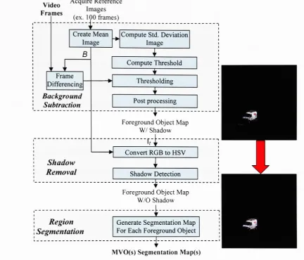
algorithm3.1 Low level Frame Analysis
The low-level frame analysis consists of three principal steps: background
subtraction, shadow suppression, and region segmentation as shown in Fig. 4. It is
utilizedto
identify
themoving objects ofinterest intwo consecutiveframes,
namely tandt+1, and provide theirrespective segmentation maps. Objects ofinterestsexhibit motion
changes through subsequent frames and are
initially
identifiedby
backgroundsubtraction. These objects consist of elementary and/or combinations of elementary
regions as labeled
by
the segmentationmodule [25]..... AcquireReference
Video .
Images Frames
, .nr.%_ .
(ex. 100IOC frames)
Create Mean Image B w Frame
Differencing
Background SubtractionCompute Std.Deviation Image ComputeThreshold
Thresholding
i
PostprocessingT-Foreground ObjectMap W/ Shadow
T
Convert RGBtoHSV
Shadow
Removal Shadow Detection
ForegroundObjectMap W/O Shadow
Region
Segmentation
Generate SegmentationMap For Each Foreground Object
i
[image:21.530.39.472.53.423.2]MVO(s)SegmentationMap(s)
Figure 4: Flowchart for low level frameanalysis.
Reference frames acquired
during
thefirst 3-4 seconds ofthevideo surveillance sequenceare used to model the background ofthe scene for the purposes of initialization and
training. In this model, each image pixelis described
by
its mean andstandarddeviation,
derived from all ofthe acquired frames. Let p(l) and cr(l) define themean and standard
deviationinlexicographic orderingat pixel location/respectively. Theseare givenby:
^r(/) =
vI/'(/) C = R,G,B.
cJ<(l) =
J^f_(i::(l)-p:(l))2
C = R,G,B.(8)
where N is the number of
training
frames,
and1,(1)
is a three-dimensionallexicographically
ordered color vectordescribing
the pixel at location / in the /-th frame(i.e. pixel's color intensities in RGB color space). The threshold utilized for
background/foregroundclassificationatpixel / is determined by:
Ac(l)
=as-ac(l)
(9)
where as is an empirically determined object segmentation constant. At a given frame t,
X(l)
is utilized to separate the moving objectsofinterest from the stationary background.This is done
by
utilizingthealgorithm described inpseudo-codebelow:For each pixel 1 in frame t:
If abs
[Ic
't(l)
-jjc(1)] > Ac(l)
pixel 1 is classified as foreground
else
pixel 1 is classified as background
Morphological operators (dilation and erosion)
[22]
are subsequently employed toremove small outliers(noiseartifacts)inthe foregroundregion(s).
It is desirable to prevent shadows from
being
misclassified as moving objects asdemonstrated in [24]. In order to achieve this, all pixel information (acquired image
frames and
background)
isconverted from RGBtoHSV colorspace (conversiondetailedinAppendix
I)
to closely correspond to the human perceptionof color [23]. Let B =[Br,
B5,
Bv]
representtheHSV componentsofthebackgroundmodel.The "shadow"pixels are
identified
by
utilizingthe setof conditions[24]
showninEquation 10 below:Shadow
(I)
1
if
a__&*fiB'd)
AND
(If(l)-Bs(l))<rs
(10)
AND
\l?(l)-BH(l)\<TH
0 Otherwise
where
I,
represents the input image (framet)
in HSV space.Hence,
the shadowinformation is comprehended
by
the ratio ofI,
to B in the Value channel and thedifference between
I,
to B in the Hue and Saturation channels. The ratio of/,
to B isbounded
by
the upper thresholdB to provide robustness to noise and the lowerthresholda to account for the strength ofthe light source responsible for the generation ofthe
shadow [24]. The thresholds x_ and th are determined empirically
depending
onlighting
conditions.Once the shadows have been properly
discounted,
the remaining foregroundobject(s) are segmented into elementary regions using a GRF-based segmentation
algorithm that utilizes both color and edge information [25]. The procedure merges two
neighboring colorregions whentheirmeans are
"similar"
andthere areno edge elements
between them. The regions in the integrated segmentation map are represented as
elementary nodes of a segmentation tree. The spatial relationships between them are
storedin anadjacency matrix.The detailsofthis algorithm aredescribed in [25].
3.2
Tracking
AlgorithmThe object
tracking
step (see Figure 5 for aflowchart)
matches and tracks potentialobjects ofinterest found in the segmentation mapsofframes tand t+1, respectively. The
found in frame t+1. The proposed
tracking
algorithm, illustrated in Figure5,
is dividedinto severalsteps as shownbelow:
1)
Generate the adjacency matrices of the elementary regions in frames t and t+1based onthesegmentation maps provided
by
thelow level frameanalysis section.2)
SelectobjectsMVO]
andMVO'.+]
as candidatesformatching.
3)
Selectthelargest elementaryregion inMVO' and
MVO1+]
respectively.
4)
Perform sub-matrix partial shape matching on the selected regions.Every
shapematch isvalidated
by
utilizingthe proceduredescribed in Section 2 followedby
asimple color distance measurement, calculated as the Euclidian distance between
the mean colors ofthe matching regions from frames / and t+1. The match is
validifthecolordistance is less thana user specifiedthreshold.
5)
If a match isfound,
combine matched regions with their respective adjacentregions and return to
Step
4. The aim of this algorithm step is toidentify
thelargest matchingcombination ofelementaryregions.
6)
Ifa matchisnotfound,
the algorithmisredirectedtoanother valid combination ofelementary regions. The aim of this step is to find any suitable partial match
betweenparts oftheobservedMVOs.
If all candidate combinations are exhausted and a partial match is not
found,
the nextobject pair
MVO' and
MVO'+1
is selected and the algorithm is redirected to
Step
3 untilall suitablecombinationsofmovingobjects inthe scenehave beenexamined.
All Objects in
previousframe
/'=/:m
AllObjects in
Currentsframe
7=/:n
Generate
Adjacency
Matrixfor
MVO',
Generate
Adjacency
Matrixfor MVOi+\
Select largest
elementaryregionin MVO'
Select largest
elementaryregionin
MVO<+\
Perform Sub-matrix Partial Shape
Matching
Validatematches
O
*_
Selectnextlargestregion of
MVOr+l
Combinethenextlargest
adjacent region of
MVO'
Select Nextpair of
Objects for matching
Expand matchingaround elementaryregionstofindthe biggestpossible matchusingpartial
matching
Storethelargest matching
combination
Assignalabeltoobject
v-Objecttracked
Figure 5: Flowchartofthe
Tracking
AlgorithmAn example ofthe above described algorithm is visually illustrated in Figure 6. To this
[image:25.530.10.486.51.598.2]segmentationmap is used to
demonstrate
the progression ofthe algorithm through Steps3, 4,
and 5. The largest elementary region of the MVO is combined with adjacentmatchedregions(see Figs.
6d-h),
resulting in full objecttracking.2 3 4 5 6 7 1 1 1 1 1 1 0 0 0 0 0 0 0 0 0 0 0 0 0 0 0 0 0 0 0 0 0 0 0 0 0 0 0 0 0 0 0 0 0
(c)
[image:26.530.26.487.94.384.2]0 0 0
Figure 6: Visual illustration for matching algorithm:
(a)
Typical movingobject,(b)
Segmentationmap,(c) Adjacency
matrix,(d)-(g)
Combinationofsuccessfullymatchedelementaryregions and
(h)
thelargestmatchHistory.There are three distinctive
tracking
scenarios based on the number of objects inconsecutive frames. There could be: a) the same number of objects in both observed
frames (object continuity),
b)
less objects inthe current framethan intheprevious frame(object merging, or object exiting the scene), and c) more objects in the current frame
than in the previous frame (object splitting and/or occlusion, or object entering the
scene). Thesescenarios areexplainedin details inthe
following
subsections.3.2.1
Case I(object continuity)Let
MVOl
andMVO'Jx
(i,j
=/,2,
..., n)denotethenumberofMVOs in framestand t+1, respectively. In this case, the number ofmoving objects in both frames is the
same (i.e. object continuity), so object
tracking
is achievedby
establishingcorrespondences for every object in frame / and t+1, respectively. The partial matching
procedure results in generating fullmatches foreach ofthe elementary regions underthe
assumptionthatall objects are visible in both frames.
3.2.2 Case II (Object
Merge/Exit)
The number ofmoving objects isreducedbetweenconsecutive frames/andt+1. The
possible scenarios are:
1)
Two or more objects"interact"
thereby
creating partial or fullocclusion from one frame to another
(e.g.,
merging oftwo moving objects is a specialcase of occlusion wherein one objectispassing in frontofthe other),
2)
Disappearance oftheobjectfrom the scene; and
3)
Parts of apreviously split object mergeto formasingleobject once again (Fig. 1 le-1 If). In orderto track the objects undergoing a"merge
",
thealgorithm uses shape templates of the MVOs undergoing occlusion (represented
by
acombinationoftheelementaryregionsdiscovered inprevious frames - Fig.
6h)
forpartialshape matching.
Thus,
the trackeridentifies and separately tracks each objectthroughouttheframes independent oftheirtranslations, rotations, scale variations,and/or occlusions.
In the event of an object exiting or
disappearing
from the scene, no correspondence is3.2.3
Case III (ObjectSplit/
Entrance)
The number ofmoving objects
increases
fromframe tto t+1. Thepossible scenarios are:1)
Entrance of new object(s) intothe scene;2)
Objects separatingafter mutual occlusion;and
3)
Splitting
of an object into pieces (occlusionby
an immovable entity or entities).New tracks are initiated for those MVO'^!,s that have not received any correspondences
to the previous frame. In the event ofsplit, the tracker assigns similar object labels for
MVOs in the current frame from the MVO of the previous frame undergoing a split
occlusion.
3.2.4 Computational Aspects ofthe
Tracking
AlgorithmThe computational aspects of the algorithm grow exponentially with the number of
tracked objects found on the scene; especially in the case of over-segmentation of
object regions. Inordertoalleviatethis, shape matching isperformedonly for MVOsthat
are within a maximum allowable spatial displacement. The value ofthat displacement is
set accordingtothe application athandandis increased proportionallyto the speed ofthe
moving objects and/or the rate of the frame acquisition. To further improve the
computational efficiencyofthe algorithm, the largestregion is selectedto startthepartial
shapematchingprocedure asdiscussed in
Step
2above. Thisleads toa smaller number ofcombinationsnecessaryto establishacompletematch.
Chapter 4
4.
Experimental
Results
andDiscussions
In this chapter, the performance ofthe proposed algorithm is demonstrated on several
simulated and real life image sequences. The sequences chosen for
testing
consist ofdifferent complex scenarios and difficulties in order to demonstrate the effectiveness of
the proposed tracker. For each sequence (Figs.
7,
9,
11, 13,
15),
the results are displayedon several non consecutive frames where the contour of the tracked objects are
highlighted followed
by
the correspondingtrajectory
paths (Figs. 8.10,
12,
14, 16). All1 _U
''
1
1
1*PJ ;
^Br1^L.
_\
1
'
/"^5'
_.
w".
[image:30.530.46.485.128.472.2](d)
(e)
(f)
Figure 7:
Tracking
resultsfor"Labsimulated"
sequence
(a)-(f)
representframes18, 59,
79,
92,
109,
and 152 (Redoutline aroundtheobjectindicatesresult oftracking
algorithm).
41
i I i I 1 1 1
-81 -121 -161 a -41 3
5, 201
--* ^ ,gs s -* ^ 5 281
-_
a k
k,
321
c.
>
~361
-401
-441
4an I I I I I 1 1 1 1 1
21 161 201 241 231 321 351 401 481 521 561 601 640
[image:31.530.27.490.61.448.2]Framewidth(pixels)
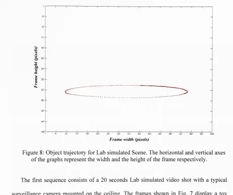
Figure 8: Object
trajectory
for Labsimulated Scene. The horizontaland vertical axesofthe graphsrepresentthewidthandtheheight oftheframe respectively.
The first sequence consists ofa 20 seconds Lab simulated video shot with a typical
surveillance camera mounted on the ceiling. The frames shown in Fig. 7
display
atoy
truckundergoingacircularmotion againstasimplebackground. Sincethe algorithm uses
shape templates (represented
by
the combination ofelementary regions generatedby
thesegmentation map from the previous
frame)
to establish correspondence in the currentframe,
and with the underlying assumption that the frame rate is 30frames/sec,
themotion ofthe object is well modeled between frames /, t+1, and frames t+1, t+2
by
anaffine transformation with possible occlusions if any.
Tracking
is accomplished(indicated
by
pinkline around object contourin Fig.7)
invariantto translations,rotations(a)
**
^
'* 1'if^u""""* *--fc
^
^^2
_^_c-^i
1
'
. .
'
mt^_
PI* *
j x
->.V^-2-X-./v
^- ^___,-.._
f
______
[image:32.530.16.484.85.461.2](d)
(e)
Figure 9:
Tracking
results for"RITParking
lot"sequence
(a)-(f)
representframes2, 11,
25,
37, 44,
and56 (Pink outlinearoundthe objectindicatesresult oftracking
algorithm).I
241
1 41 121 161 201 241 231 321 361 401 441 521 561 601 640
[image:33.530.37.487.60.414.2]Framewidth(pixels)
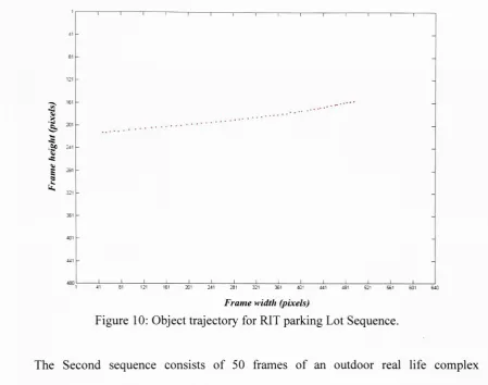
Figure 10: Object
trajectory
for RIT parking Lot Sequence.The Second sequence consists of 50 frames of an outdoor real life complex
background video typical totheones captured on surveillance cameras in sportsstadiums
or secure type facilities. The frames shown in Fig. 9
display
atruck that is moving fromright to left in the scene where its projected 2D shape is
being
changed due to 3Dtranslations androtations. Inaddition, minorocclusionsarecreated
by
the presenceofthepole in the scene. The proposed algorithm was capable of segmenting,
isolating
andtracking
(see Fig.10)
the moving object successfullythroughoutthe video (see pinklineFigure 1 1:
Tracking
results for"toy
cars"
sequence
(a)-(f)
representframes8,
20, 26, 30,
33,
and38(Yellowand pink outline aroundthe objectsindicatesresult oftracking
algorithm).1
is
SP 4)
g 3
4
Toytruck Toycar
Toy
carduring
split41 61 81 101
Framewidth(pixels)
[image:35.530.46.489.66.525.2]181 201 241 261 280
Figure 12: Object
trajectory
for"Toy
Car"Sequence.
The third sequence consists of40 frames of a lab video sequence in which a
toy
carand truck are moving in opposite directions. Note that the car undergoes various
scenarios ofpartial occlusion due to the presence ofthe box in the scene where in some
frames the front and rear end of the car are visible while the center section is
totally
occluded. Fig. 1 lb-1 Ifshowsthe bluetruckand green car
being
trackedby
the proposedalgorithm, where each object is given a unique label. The front end ofthe green car is
being
progressively occluded (Fig.lib,
lie),
displays a"split"
occlusion scenario
-center section occluded - (Fig.
lid,
lie)
resulting in 2 objects, andthenprogressive backend de-occlusion (Fig. llf). The algorithm still manages to assign the same object label
to the car and truck objects
by
using the partial shape matching module. TheFigure 13:
Tracking
results for"RITjunction"sequence(a)-(b)
frames25,
26(c)-(d)
frames
29,
30 (e)frame 32(f)-(h)
frames34,
35,37and(i)
frame 38(Yellowand pinkoutline aroundtheobjectsindicatesresultof
tracking
algorithm).a
.Sp,0 s
M12
s
I"
DVan DVan
during
Merge ^Truck ^Truckduring
Mergearoo-cp ? ? 0 D
C P D c ? D L3
1 21 41 61 26"
231 301 320
[image:37.530.15.488.61.339.2]Framewidth(pixels)
Figure 14: Objecttrajectories(frames 20to
38)
for RIT Junction Sequence.The fourth sequence consists of a 10 second outdoor, real
life,
video sequenceacquired, with ahand held video camera, at a roadjunction at the Rochester Institute of
Technology. The sequence was selected to test the robustness of the algorithm where
occlusions are
being
createdby
foreground andbackground moving objects. The framesshown in Fig. 13
display
atruck and avan approaching eachother (Fig.13a)
resulting inan early partial occlusion which lasts for approximately 10-12
frames,
developing
progressive occlusion (Fig.
13b, 13c),
undergoing severe occlusion (Fig.13d),
and thenprogressive de-occlusion (Fig. 13f,
13h)
andfinally
asplit (Fig. 13i). To indicate this,thematched objectboundariesare highlightedin
"yellow"
and
"purple"
for
display
purposes.Figure 13e displays the truckis
heavily
occludedby
the van in frame32,
the trackerfailsto establishacorrespondence forthe truck sincethe area encompassed
by
it is insufficientafter it has reappeared with sufficient enough frame size. The proposed algorithm
effectively tracks (see Figure
14)
each object independent of the occlusion scenariothroughout the sequence.
_*_____
Figure 15-
Tracking
resultsfor "Parking Lot"sequence
(a)-(i)
representframes4, 24. 36.48,
62, 70,74,
80,and92 [image:38.530.12.485.69.728.2]1 41 81 121 21 * a -S> 201 S Sp
^ 241
-;--.... J. ~ 321 361 401 441 APft -ii
1 41 61 121 161 201 241 281 321 361 401 441 481 521 561 601 641 681 720
[image:39.530.16.478.59.364.2]Framewidth(pixels)
Figure 16:Trajectoriesoftheobjectsfor parking Lot Sequence.
Figure 1 5 shows
tracking
results from sample frames of a typical surveillance sequenceshot at aparking lotwherethe twocars undergotranslation, rotation, scale variationsand
merging. In contrast to the previous scene, the objects ofinterest possess similar colors
and shape in order to stress the
tracking
algorithm. Fig. 17(a)
shows the regions(segmentationmap) ofthe objects
being
tracked in frame 68. Theseare used as templatesfor shape matching in frame 69 and so on as the objects are undergoing a
"merge"
operation. Table 1 provides the corresponding Hausdorff distance values
(similarity
measuredetailed inappendix
II)
foreach ofthe objectsthroughoutseveral frames.Thus,
given the data in Table 1, it is evident that the proposed
tracking
algorithm was capableof successfully
handling
the "merge" scenarios shown in Figure 15 (i.e. assigning a(a)
(b)
(c)
(d)
Figure 17:
(a)-(d)
Objectregionsdiscovered intheframesas labeledabove.Frame No. Object 1 Template Object 2 Template
72
Object 1 23.09 29.61
Object 2 37.48 23.54
74
Object 1 11.70 46.84
Object 2 31.02 28.02
80
Object 1 08.60 35.22
[image:40.530.59.489.255.375.2]Object 2 58.83 22.00
Table 1:
Similarity
Metric forshape: Objectsofframe 68(Templates)
comparedtoObjectsofframe
72,
74& 80 undergoingmerging.Table 2 lists the typical
MVO(s)
size, frame size, number offrames and the processingtime utilized
by
theproposedtracking
algorithm forthe above sequences. The algorithmwas prototyped in a MATLAB
[28]
environment. The processing time per frame isdirectly
proportional to thenumber ofelementaryregions (generatedby
thesegmentationmodule) present in a segmentation map of a given MVO and the number of MVO's
present in the scene. Note that the processing speeds for video Sequences 1 and 2 are
almost equivalent since
they
both possess a single MVO and the same number ofelementaryregions
(typically
2 -3)as generatedby
the segmentation map. WhereasvideoSequence 4 with two MVO's takes approximately 5 times more processing time per
frame as compared to video Sequences 3 and
5,
alsowith two MVO's. This is dueto thefact that the segmentation map for Sequence 4 consists
typically
of 5-6 regions for agiven MVO as opposed to 2-3 regions for a given MVO in Sequences 3 and 5. These
algorithms can be made to operate in real or near real time using hardware
implementations.
Videosequence
Object(s)
size
(Pixels)
Frame
size
(Pixels)
No.of
frames
processed
Total
processing
time
(sees)
Processing
time/frame
(sees)
No. Name
1 Labsimulated 135x60 640x480 285 2920.11 10.2
2 RIT
Parking
Lot 110x70 640x480 65 756.10 11.63 "Toy 80x40
65x35
280x 180 40 1280 32
4 RIT Junction 124x54
108x50
320x240 40 4800 120
5
Parking
Lot 145x6077x34
720x480 100 2200 22
[image:41.530.53.483.237.403.2]Chapter 5
5. Conclusions
andFuture Work
This thesis describes a
tracking
algorithm that utilizes partial shape matching to trackobjects in video surveillance applications. The algorithm is capable of
handling
translations, rotations, scale variations and is effective in instances of occlusions. The
approach was successfully tested on several video surveillance sequences. The
performance of the tracker requires that the region(s) that constitute the object(s) be
clearly separated
by
the segmentationalgorithmfromthe"clutter". It shouldbe notedthat39-any effective region segmentation technique could be utilized to perform this particular
step. In addition to generating meaningful regions the segmentation should generate less
number of elementary regions so as to reduce the computational cost ofthe matching
procedure. In instances where the object has undergone full occlusions and then re
appeared in the scene (grow in size), it may take more than 1 frame to re-establish
tracking
(as shown in RITjunction Sequence Fig. 13e-13f). Non stationary cameras canbehandledusingtheproposed algorithm
by
performingfrequentbackgroundupdates.ObiectDatabase _^f
g
Video Camera1 Low-Level FrameAnalysis Video Camera2 Object Recognition &Tracking Low-Level FrameAnalysisT
I
Object Recognition &TrackingT
Video Camera N "_________Z^ Low-Level FrameAnalysis Object Recognition &Trackingt
.Camera1 though N >.
Svit
Inter Camera Fusion ihinCahjenri^rocess^nt Inter Camera Fusion Camera Fusion Account for: *PotentialOcclusionsin
Camera(s)Viewpoint
Segmentation Errors.
*
ShapeMatchingErrors betweena givenframeand object ofinterest
[image:43.530.56.476.258.560.2]Object Tracked in Multiple Video 2:
Figure 18: Object
Tracking
andRecognition using Multiple Multimodal Sensors.In future studies, a planto
develop
an informationfusion frameworkas shown in Fig.1 8 is
being
considered, that takes advantage ofthe data generatedby
multiple sensors-due to their collective ability to collect data from multiple angles/views - to
enhance the object
tracking
and recognition and compensate for potential occlusions asviewed
by
a given sensor. In the general case, all sensors would be utilized, in an"intersensor
processing"
framework,
to improvetracking
and recognition.Appendix
T
-RGR
to
HSV Transformation
RGB is anm-by-n-by-3 image arraywhose three planes containthe red, green, and blue
components forthe
image,
whileHSV is anm-by-n-by-3 image arraywhose threeplanescontain the
hue,
saturation, and value components for the image. Where hue is an anglefrom 0 to 360
degrees,
typically
0 is red, 60 degrees yellow, 120 degrees green, 180degrees cyan, 240 degrees
blue,
and 300 degrees magenta. Saturationtypically
rangesfrom 0 to 1 (sometimes 0 to 1
00%)
and defines how greythe color is. Value is similartoluminance except it also varies the color saturation. The transformation between RGB
and HSVis givenby:
[6
if
B<G H=\
J
(1)
[360
-<9if
B>Ga -if
0.5[(R-G)
+
(R-B)]
|
#= COS
|
l-^y
(2)
ll(R-G)-+(R-B)(G-B)\ \
5 =1-
-I
\mm(R,G,B)]
(3)
R+B+G
I=-(R+G+
B)
(4)
Appendix
TT
-Hausdorff
Distance
for
Comparing
Images
Hausdorff distance is used to measure the resemblance between two objects that are
superimposed on one another (as shown in Fig. 1 8). This similarity metric for a given
pairofobjects iscomputed as follows.
Given the image region and the example template's point set A=
{al,....}
andB ={bl,b2...} respectively,the hausdroff distance is definedas,
H(A,B)
=max(h(A,B),h(B,A))
(1)
Where,
h(A,
B)
- max min a-b\\
ae.4 beB " "
(2)
and
II
is the Euclidean norm. The Hausdorffdistance,
H(A,B),
is the maximum ofh(A,B)
andh(B,A)
. Thus measures the mismatch betweentwo sets,by
measuring thedistance ofthe point A that is farthest from any point B (the most mismatched point of
A)
givenby h(A,B)
and vice versa.Imaae
Template
Figure 19: Template & imagesuperimposedfor measuring similaritymetric
43-References
[1]
J. Y. A.Wang
and E. H.Adelson,
"Representing
moving images withlayers,"
IEEE Trans. Image
Processing,
vol.3,
no.5,
pp.625-638,
Sept. 1994.[2]
M.Irani,
B.Rousso,
and S.Peleg,
"Computing
occluding and transparentmotions,"
Int. J. Comp.
Vision,
vol.12,
Feb. 1994.[3]
A. M.Tekalp,
Digital VideoProcessing,
PrenticeHall,
1995.[4]
J. F. Haddon and J. F.Boyce,
"Image segmentationby
unifying region andboundary
information," IEEE Trans. Patt. Anal. Mack Intel., vol.PAMI-12,
pp.929-948,
Oct. 1990.[5]
C. C.Chu,
J. K.Aggarwal,
"The integration of image segmentation maps usingregion and edge
information,"
IEEE Trans. Patt. Anal. Mach.
Intel.,
vol.15,
pp.1241-1252,
Dec. 1993.[6]
E.Saber,
A. M.Tekalp,
G.Bozdagi,
"Fusion of color and edge information for improved segmentation and edgelinking,"
Image and Vision
Computing,
vol.15,
1997.
[7]
Y.Altunbasak,
E.Eren,
and A. M.Tekalp,
"Region-based affine motionsegmentation using color information," Graph. Models and Image
Processing,
vol.
60(1),
pp.13-23,
Jan. 1998.[8]
R. T.Collins,
et al., "A System for Video Surveillance andMonitoring
(VSAM),
Tech. report
CMU-RI-TR-00-12,
RoboticsInstitute,
Carnegie MellonUniversity,
May,
2000.[9]
C. R.Wren,
A.Azarbayejani,
T.Darrell,
and A.Pentland,
"Pfinder: Real-timetracking
ofthehuman body,"IEEE Trans. Patt. Anal. Mach.
Intel.,
vol.19,
no.7,
pp.
780-785,
1997.[10]
M. Isard and A.Blake,
"Condensation - Conditionaldensity
propagation forvisual
tracking,"
Int. J. Computer
Vision,
vol.29,
no.1,
pp.5-28,
1998.[11]
D.Comaniciu,
V.Ramesh,
and P.Meer,
''Real-timetracking
ofnon-rigid objectsusing mean
shift,"
[12]
Y.Fu,
A. T.Erdem,
and A. M.Tekalp,
"Tracking
visibleboundary
of objectsusing occlusion adaptive motion
snake,"
IEEE Trans. Image
Processing,
vol.9,
no.
12,
pp.2051-2060,
Dec. 2000.[13]
H. Nguyen and A. W. M.Smeulders,
"Fast occluded objecttracking
by
a robustappearance filter," IEEE Trans. Patt. Anal. Mach.
Intel,
vol.26,
no.8,
pp.1099-1104,
August, 2004.[14]
D.Comaniciu,
V.Ramesh,
and P.Meer,
"Kernel-based objecttracking,"
IEEE
Trans. Patt. Anal. Mach. Intel,vol.
25,
no.5,
pp.564-577, May,
2003.[15]
F.Aheme,
N.Thacker,
andP.Rockett,
"The Bhattacharyya Metric asanAbsoluteSimilarity
Measure forFrequency
Coded Data,"Kybernetika,
vol.34,
no.4,
pp.363-368,
1998.[16]
Z. Shaohua and R. Chellappa, "Simultaneoustracking
and recognition ofhumanfaces fromvideo,"
Proc. ICME '03, vol.
3,
pp.129-132,
6-9July
2003.[17]
S. Dockstader and A. M.Tekalp,
"Multiple cameratracking
ofinteracting
andoccluded human
motion,"
Proc. oftheIEEE, vol.
89,
no.10,
pp.1441-1455,
Oct. 2001.[18]
S.Dockstader,
M. J.Berg,
and A. M.Tekalp,
"Stochastic kinematics modelingand feature extraction for gait
analysis,"
IEEE Trans. Image
Processing,
vol.12,
no.8,
Aug. 2003.[19]
C.Erdem,
B. Sankur, andA. M.Tekalp,
"Performancemeasuresforvideo object segmentation andtracking,"
IEEE Trans. ImageProcessing, 2003.
[20]
D.Huttenlocher,
D.Klanderman,
and A.Rucklige, "Comparing
images using theHausdorffdistance," IEEE Trans. Patt. Anal. Mach.
Intel,
vol.15,
no.9,
pp.850-863,
Sept. 1993.[21]
S.Sun,
D. R.Haynor,
and Y.Kim,
"Semiautomatic video object segmentationusing
VSnakes,"
IEEE Trans. Circuits Syst. Video Technol. vol. 13. no.
1,
pp.75-82,
Jan. 2003.[22]
R. C.Gonzalez,
R. E. Woods, Digital ImageProcessing
2ndEdition,
PrenticeHall,
NewJersey,
2002.[23]
N.Herodotou,
K.N.Platanitotis,
and A.N.Venetsanopoulos,
"A ColorSegmentation Scheme for Object-Based Video Coding," Proc. IEEE Symp.
Advances inDigital
Filtering
andSignalProcessing,
pp.25-29,
1998.[24]
R.Cucchiara,
C.Grana,
M.Piccardi,
and A.Prati,
"Statisticand knowledge-basedmovingobjectdetection intraffic scenes,"
Proc. oflTSC,pp.
27-32,
2000.[25]
E.Saber,
A. M.Tekalp,
G.Bozdagi,
"Fusion ofColor and Edge Information forImproved SegmentationandEdgeLinking,"Image & Vis.
Comp.,
1997.[26]
E.Saber,
YaowuXu,
A. M.Tekalp,
"Partial shape recognitionby
sub-matrixmatching for partial matching guided image
labeling,"
Pattern Recognition, Vol.
38,pp. 1560-1573, 2005.
[27]
D. Chetyerikov andZs.Szabo,
"A simple and efficientAlgorithm for detectionofhigh Curvature Points in Planar Curves,"
Proc. 23rd
Workshop
Austrian Patt. Recog.Group,
pp.175-184,
1999.