UNIVERSITI TEKNIKAL MALAYSIA MELAKA
TEMPERATURE CONTROL DEVICE DESIGN FOR ELECTRIC
KETTLE USING BANG-BANG CONTROLLER
This report is submitted in accordance with the requirement of the Universiti Teknikal Malaysia Melaka (UTeM) for the Bachelor of Electrical Engineering
Technology (Industrial Automation & Robotics) with Honours.
by
FARIS BIN SAMSUDIN B071310595 940209086053
TAJUK: TEMPERATURE CONTROL DEVICE DESIGN FOR ELECTRIC KETTLE
USING BANG-BANG CONTROLLER
SESI PENGAJIAN: 2015/16 Semester 2
Saya FARIS BIN SAMSUDIN
mengaku membenarkan Laporan PSM ini disimpan di Perpustakaan Universiti Teknikal Malaysia Melaka (UTeM) dengan syarat-syarat kegunaan seperti berikut:
1. Laporan PSM adalah hak milik Universiti Teknikal Malaysia Melaka dan penulis. 2. Perpustakaan Universiti Teknikal Malaysia Melaka dibenarkan membuat salinan
untuk tujuan pengajian sahaja dengan izin penulis.
3. Perpustakaan dibenarkan membuat salinan laporan PSM ini sebagai bahan pertukaran antara institusi pengajian tinggi.
4. **Sila tandakan (SULIT )
(Mengandungi maklumat TERHAD yang telah ditentukan oleh organisasi/badan di mana penyelidikan dijalankan)
UNIVERSITI TEKNIKAL MALAYSIA MELAKA
Disahkan oleh:
BORANG PENGESAHAN STATUS LAPORAN PROJEK SARJANA MUDA
Cop Rasmi:
Tarikh: _______________________ TERHAD
/ TIDAK TERHAD
(Mengandungi maklumat yang berdarjah keselamatan atau kepentingan Malaysia sebagaimana yang termaktub dalam AKTA RAHSIA RASMI 1972)
Alamat Tetap:
No 16, Laluan 41, Taman Klebang Jaya,
31200, Chemor, Perak
Tarikh: ________________________
iii
DECLARATION
I hereby,declared this report entitled “Temperature Control Device Design for Electric Kettle using Bang-Bang Controller” is the results of my own research
except as cited in references.
Signature : ………
Author’s Name : FARIS BIN SAMSUDIN
iv
APPROVAL
This report is submitted to the Faculty of Engineering Technology of UTeM as a partial fulfillment of the requirements for the degree of Bachelors of Electrical Engineering Technology (Industrial Automation and Robotics). The member of the supervisory is as follow:
v
ABSTRAK
vi
ABSTRACT
vii
DEDICATION
To my beloved parents To my kind lecturers
And not to forget all my fellow friends
viii
ACKNOWLEDGEMENT
Before, while and after I doing my job to complete this project, I have received so many help from my supervisors, lecturers, researchers, family members and also my fellow friends.
First and foremost, I want to give my thanks to my supervisor, Dr Mohd Badril Bin Nor Shah who gave me a lot of encouragement, a true guidance and very supportive.
Besides, I also thankful to my parents for supporting me on mentally and financially for almost part for this project. It’s the most things that I need.
ix
TABLE OF CONTENT
Abstrak v
Abtract vi
Dedication vii
Acknowledgement viii
Table of Content ix
List of Tables xi
List of Figures xii
CHAPTER 1: INTRODUCTION 1
1.0 Project Background 1
1.1 Problem Statement 2
1.2 Objectives 2
1.3 Work Scope 3
1.4 Thesis Outline 4
CHAPTER 2: LITERETURE REVIEW 5
2.0 Introduction 5
2.1 Microcontroller 6
2.2 Controller 14
2.3 Sensor 16
2.4 Arduino(IDE) 18
2.5 Previous Related Works 18
CHAPTER 3: METHODOLOGY 20
3.0 Introduction 20
3.1 Circuit Design 21
x
3.1.2 Step-down Transformer and Rectifier 23
3.1.3 Seven-segment Display 23
3.1.4 Interfacing Relay 24
3.1.5 Temperature sensor 24
3.2 Controller Design 25
3.3 Hardware Development 27
3.4 Program Development 28
CHAPTER 4: RESULT & DISCUSSION 30
4.0 Introduction 30
4.1 Circuit Simulation 30
4.2 Experiment Results 31
CHAPTER 5: CONCLUSION & FUTURE WORK 34
5.0 Conclusion 34
5.1 Recommendation of Future Work 36
REFERENCES 37
APPENDICES
xi
LIST OF TABLE
xii
LIST OF FIGURES
1.1 Common internal structure of an electric kettle 1
2.1 PIC 16F877A 6
2.2 Arduino Uno Board 7
2.3 Atmega328 Mapping 8
2.4 Arduino UNO board description 11
2.5 USB Micro B cable 14
2.6 Fuzzy logic controller block diagram 15
2.7 Block diagram bang-bang control 15
2.8 The response of bang-bang control 16
2.9 LM35DZ temperature sensor 17
2.10 Arduino Software 18
3.1 The flowchart of methodology of this project 21
3.2 Arduino UNO microcontroller 22
3.3 8-digit SSD 23
3.4 SSR as an interfacing relay 24
3.5 DS18B20 temperature sensor 25
3.6 The block diagram of bang-bang control for temperature 26
control of electric kettle
3.7 Field diagram for the proposed circuit of this project 27
3.8 The hardware prototype of this project 27
3.9 Programming flowchart of this project 29
4.1 Simulation using Online Arduino Simulator 30
4.2 Response of water temperature at desired temperature Tref = 60°C 31
4.3 Response of water temperature for case Tref = 75°C 32
4.4 The response of water temperature when temperature sensor is 33
1
CHAPTER 1
INTRODUCTION
1.0 Project Background
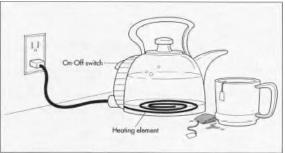
An electric kettle normally intended to boil water. The main component that responsible to heat-up the water is a heat element which is powered by electrical energy. When the water inside kettle is reached at the boiling point (100oC), the
[image:13.595.195.480.379.532.2]generated steam pressure will induce a cut-off switch to stop the heating process. Figure 1.1 shows the common internal structure of an electric kettle.
Figure 1.1: Common internal structure of an electric kettle
An electric kettle usually does not equipped with temperature display and temperature control capability. These contraints has prevent for those who want warm-up the water at specific temperature. For such temperature control purpose, a bang-bang controller can be used to control the electrical energy that supplied to heat elemet of kettle.
2
power supply control. The advantages of this controller are ease to design and also robust to disturbance and parameter uncertainties.
1.1 Problem Statement
An electric kettle regularly intended to boil water. It generally does not give temperature display and temperature control capability. Because of their constrained abilities, an electric kettle just can fill one purpose; to produce boiled water. There would be a great favorable circumstances if an electric kettle has ability to set and keep up at the water temperature set by user.
There are many applications can be adopted if an electric kettle is able to produce warm water at desired level temperature. For example, at 40oC water
temperature, a guardian can prepare formula milk for their babies or toddlers. A coffee enthusiast always required heated water of 92oC for brewing a delicious
coffee drink. For cookies or cakes maker, warm water at 60oC will help them to
prepare perfecly mixed dough.
By having an external device that can control temperature at the desired level, user does not have to buy an expensive water warmer or similar device to obtain their preferred warm water. By using a cheap electric kettle and the proposed device that is developed in this project, user is able to obtain the warm water as they intended.
1.2 Objectives
The objective of this project are :
a) To design a circuit of temperature control device for electric kettle
3
c) To develop temperature control device complete with user interface and temperature display
1.3 Work Scope
The scopes of this project are :
a) Circuit design
Microcontroller – based circuit that will be designed for this project, where it will be connected to electric kettle. A rectifier – based power supply circuit is also included in the design.
b) Controller design
To provide precise temperature control of water in electric kettle based on desired temperature set by user, closed loop control design is required.
c) Simulation
The performance of the designed closed-loop control of temperature control for electric kettle is analyzed through simulation.
d) Hardware prototype
A hardware prototype of this project will be developed to verify the efficiency of the designed controller and the circuit.
e) Electric kettle type
4
1.4 Thesis Outline
This thesis consists of five chapter and are organized as follows. Chapter 2 provides a literature review on information that is related in developing this project. The review of hardware components and several related previous works are also included in this chapter.
Chapter 3 provides the details methodology of process development. It covers the circuit design, hardware and programming development.
Chapter 4 discussed the results from simulation model circuit and hardware prototype. The analysis of results are also explained in this chapter.
5
CHAPTER 2
LITERETURE REVIEW
2.0 Introduction
Literature review is the critical strategy for engineers before they build up their task. Literature review expect to scrutinize the same number of as source to helping engineers to inspire thought to build up the undertaking. The movement included looking, gathering, investigating and reaching inference from all level headed discussions and issues brought up in pertinent assortment of writing. For create temperature control device project, it have to do research and gather related data of this anticipate with past undertakings. From that can make correlation between past project and project need to create. There are numerous approaches to lead writing survey, for example, from web, journal, books, specialized reports, continuing referens, unknown reference, and e-book.
6
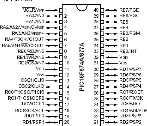
2.1 Microcontroller
[image:18.595.203.460.323.543.2]PIC 16F877A microcontroller enhances the execution of the temperature control by making significant change in rising also, settling time, moreover, diminishing overshoot and consistent state mistake contrasted with a customary PID controller proposed by Mimura, K., & Shiotsuki, T. (2007). Consolidated technique of criticism control, iterative learning encourage forward technique firmly around the set point amid ordinary operation is tried. Perfect condition of the machine and move kill the inhomogeneous issue for the responding screw infusion forming machine by Somesh, B. S., Mukherjee, A., Sen, S., & Karmakar, P. (2014).
7
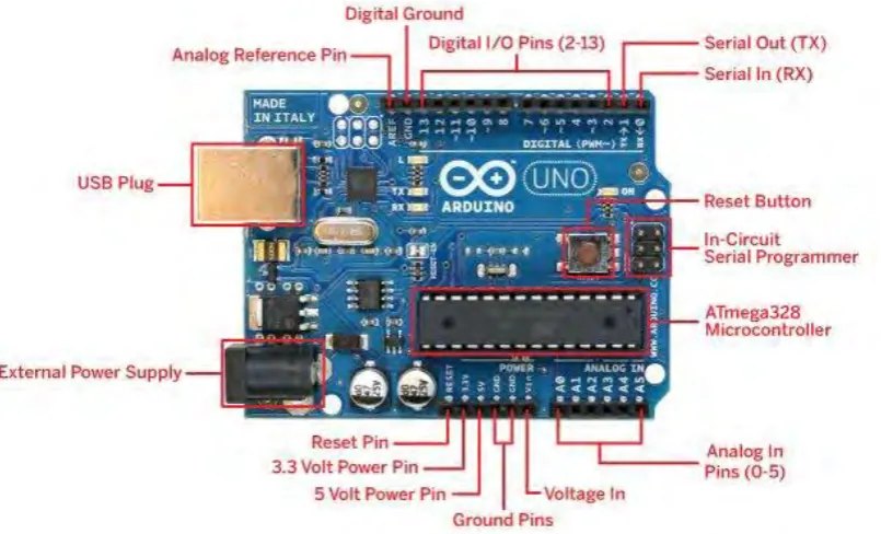
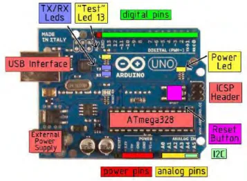
[image:19.595.125.528.415.659.2]According to Miah et al. (2015), Arduino is laid out as open-source devices prototyping stage giving schematics and versatile progression packs for enthusiastic customers who intend to convey natural things or circumstances. The Arduino Uno board is a microcontroller in light of the ATmega328. It comprises of 14 computerized input/output pins out of which there are 6 pins that can be utilized as PWM yields, a 16 MHz artistic resonator, an ICSP header, a USB association, there are 6 analog inputs pins, a power jack and a reset button. This contains all the needed help required for microcontroller. For the associating with a PC it utilizes a USB link. Additionally with an AC-to-DC connector or battery it can be fueled on. Arduino Uno Board shifts from all different sheets and they won't utilize the FTDI USB-to-serial driver chip in them. It is highlighted by the Atmega16U2 (Atmega8U2 up to form R2) modified as a USB-to-serial converter. According to Weeks, M. (2015), Arduino is an open prototyping stage in view of ATmega processor records and dialect, for example, C programming environment change, and could be connected with an assortment of COTS sensors.
8
Technical Specification
14 digital input/output pins (6 pins can be used as pwm output)
6 analog inputs, a 16 MHz crystal oscillator
USB connection
Power jack
ICSP header
Reset button
[image:20.595.115.567.315.582.2] Serial Out (TX), Serial In (RX)
9
Technical specification
Microcontroller : ATmega328P
Operating Voltage : 5V
Input Voltage (recommended) : 7-12V
Input Voltage (limit) : 6-20V
Digital I/O Pins : 14 (of which 6 provide PWM output)
PWM Digital I/O Pins : 6
Analog Input Pins : 6
DC Current per I/O Pin : 20 mA
DC Current for 3.3V Pin : 50 mA
Flash Memory : 32 KB (ATmega328P) of which 0.5 KB used by bootloader
SRAM : 2 KB (ATmega328P)
EEPROM : 1 KB (ATmega328P)
Clock Speed : 16 MHz
Length : 68.6 mm
Width : 53.4 mm
Weight : 25 g
10
Utilizing an Arduino streamlines the use of equipment and programming advancement need to do keeping in mind the end goal to get the system running and can control effectively.
The Arduino equipment stage as of now elements power and reset hardware setup and also hardware to handle and speak with the microcontroller over USB. Furthermore, ones I/O pins of any microcontroller are normally as of now encouraged out to attachments/headers expected for simple openness (This may differ a bit with the particular model).
For the product side, Arduino gives various libraries to make programming for the microcontroller less demanding. The most straightforward connected with these is to control and read the I/O pins. More valuable are things, for example, having the capacity to set I/O pins to PWM certain obligation cycle utilizing a solitary order or doing Serial correspondence.
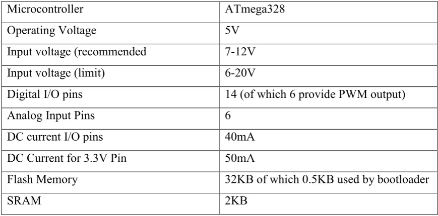
[image:22.595.101.536.517.732.2]Arduino UNO additionally is an open source, so people groups that need to utilized it does not have to purchase the first, yet the clones version which are produced by merchants can be purchased. Table 2.1 demonstrates the Arduino UNO board detail. Figure 2.4 demonstrates the Arduino UNO board depiction.
Table 2.1: Technical specification of Arduino UNO board
Microcontroller ATmega328
Operating Voltage 5V
Input voltage (recommended 7-12V
Input voltage (limit) 6-20V
Digital I/O pins 14 (of which 6 provide PWM output)
Analog Input Pins 6
DC current I/O pins 40mA
DC Current for 3.3V Pin 50mA
Flash Memory 32KB of which 0.5KB used by bootloader
11
Figure 2.4: Arduino UNO board description
12
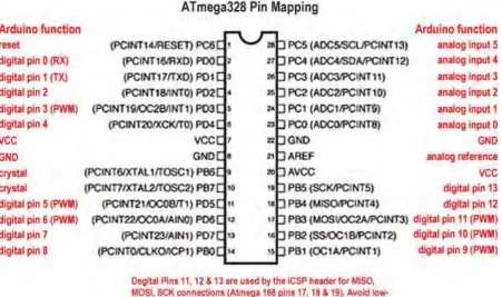
The ATmega328 has 32 KB flash memory to put away the code (where 0.5 KB used for the boot loader), it has an additional 2 KB of SRAM and 1 KB of EEPROM (which can be read and composed with the EEPROM library).
Each of the 14 propelled sticks towards the Arduino UNO might be utilized as a conceivable data or even yield, applying pinMode (), digitalWrite (), and digitalRead () limits. They work from a couple of volts. Each pin will unquestionably offer or even make application for a most huge including 40mA and has the internal draw up resistor (confined obviously) associated with 20-50kOhms. Moreover, some pins have customized limits:
Serial: 0 (RX) and 1 (TX). Used to get (RX) and transmit (TX) TTL serial information. These pins are associated with the relating pins of the ATmega8U2 USB-to-TTL Serial chip.
External Interrupts: 2 and 3. These pins can be designed to trigger a hinder on a low esteem, a rising or falling edge, or an adjustment in quality. See the attachInterrupt () capacity for subtle elements.
PWM: 3, 5, 6, 9, 10, and 11. Give 8-bit PWM yield with the analogWrite() capacity.
SPI: 10 (SS), 11 (MOSI), 12 (MISO), 13 (SCK). These pins bolster SPI correspondence, which, in spite of the fact that gave by the hidden equipment, is not as of now incorporated into the Arduino dialect
LED: 13. There is an implicit LED associated with advanced pin 13. At the point when the pin is HIGH esteem, the LED is on, when the pin is LOW, it's off.