Mathematical modelling of flexural waves in structured
elastic plates
Thesis submitted in accordance with the requirements of the University of Liverpool for the degree of Doctor in Philosophy
by
Abstract
This thesis discusses properties of flexural waves in thin elastic plates that incorporate a structured system of gratings of defects. The defects may take the form of inclusions or masses, but we focus on circular inclusions, and in particular, holes with a clamped edge. We place the work in the relatively new field of platonics, which is the study of flexural waves in plates governed by the fourth-order biharmonic plate equation. By analogy with photonic and phononic crystals, the two-dimensional structures in thin elastic plates are known as platonic crystals.
We present a novel analysis of trapped modes and transmission resonances in grating stacks, arising from the interaction with plane waves incident on the gratings. We show that the evanescent modes are important in demonstrating interesting and unusual filtering effects. In particular we analyse the previously unstudied effect of elasto-dynamically inhibited transmission (EDIT), where a resonance in transmission is cut in two by a resonant minimum arising from destructive interference. Similar destructive interference-induced phenomena have been observed in other settings, notably classical optical oscillators, metamaterials and plasmonics, but we are the first to do it for flexural plates.
The phenomenon of EDIT is a central theme of this thesis, and is linked to the analysis of even and odd Bloch modes in the grating waveguides. We develop a method that identifies the parameters of the model, the relative separationsη and lateral shifts ξ of the gratings, and the spectral parameterβ and angle of incidence θi of the plane
wave, to find EDIT efficiently.
The method is powerful and universal, based on a recurrence procedure for the construction of reflection and transmission matrices. A multipole method is employed for circular scatterers and the limiting case of rigid pins, whereby the solutions are determined analytically. Recent developments have also been made with arbitrarily-shaped holes, and other future research is likely to focus on the association with Dirac-like cones that are linked to the standing modes arising in platonic crystals.
Contents
Abstract i
Contents ii
List of Figures v
Acknowledgements xv
List of Publications xvi
1 Introduction and background 1
2 Underlying theory 8
2.1 Governing equation . . . 8
2.1.1 Structured interaction region . . . 9
2.2 Plane wave representations of scattered waves . . . 11
2.3 Quasi-periodicity conditions . . . 13
2.3.1 Direct lattice and reciprocal lattice . . . 14
2.3.2 Dispersion of Bloch waves and band diagrams . . . 16
2.4 Concepts from classical optics . . . 17
2.4.1 Diffraction grating . . . 17
2.4.2 Efficiency curves and Wood anomalies . . . 20
2.4.3 Stokes-Helmholtz reciprocity principle . . . 22
2.4.4 Fabry-P´erot theory . . . 23
2.4.5 Electromagnetically induced transparency . . . 27
2.5 Spectral problem for biharmonic operator for doubly periodic square array 29 2.5.1 Governing equations . . . 30
2.5.2 Multipoles . . . 31
2.5.3 Boundary conditions and their multipole representations . . . 32
2.5.4 Rayleigh identities and lattice sums . . . 33
2.5.5 Band diagrams and stop-bands . . . 36
2.6 Green’s functions . . . 38
2.6.1 Quasi-periodic Green’s function for an infinite grating of circular
scatterers . . . 39
3 Method of solution for a platonic grating stack 45 3.1 Multipole method . . . 47
3.1.1 Governing equations . . . 48
3.1.2 Multipoles . . . 49
3.1.3 Rayleigh identities . . . 50
3.1.4 Reconstruction equations . . . 54
3.1.5 Conservation of energy . . . 56
3.1.6 Zero-radius limit: rigid pins . . . 62
3.2 Recurrence algorithm for multipole method . . . 65
3.2.1 Propagation matrices . . . 66
3.2.2 Geometric series . . . 68
3.2.3 Enhanced transmission . . . 69
3.3 Waveguide approach . . . 72
3.3.1 Grating Green’s function: plane wave form . . . 73
3.3.2 Mode symmetry in a general triplet stack . . . 73
3.4 Analysis of transmission resonances . . . 74
4 Pinned platonic grating stacks 78 4.1 Pairs of rigid-pin platonic gratings . . . 79
4.1.1 Varying angle of incidence . . . 79
4.1.2 Varying relative grating separation and analogy with Fabry-P´erot theory . . . 81
4.2 Triplets of rigid-pin platonic gratings . . . 83
4.2.1 Numerical results for symmetric triplets . . . 85
4.2.2 Odd and even modes . . . 85
4.2.3 Quality factors for the trapped modes . . . 87
4.3 Double resonances and the analogy with EIT . . . 88
5 Nonzero-radius platonic grating stacks 91 5.1 Governing equations: scattering by a single grating . . . 93
5.2 Transmission and reflection properties of a single grating . . . 94
5.3 Transmission resonance for pairs of aligned gratings: normal incidence . 96 5.3.1 Examples for various nonzero radii . . . 97
5.3.2 Convergence properties . . . 98
5.4 Transmission resonance for pairs of aligned gratings: oblique incidence . 100 5.5 Controlling transmission resonances for triplets of gratings . . . 102
5.5.1 Triplets of identical gratings . . . 103
5.5.2 Non-uniform triplets with rigid pins on the exterior boundary . . 105
5.5.3 Non-uniform triplets with rigid pins in the central grating . . . . 106
5.6 Shifted systems of gratings and the EDIT phenomenon . . . 108
5.7 EDIT examples without rigid pins . . . 110
6 Symmetry and resonant modes in platonic grating stacks 113 6.1 Structured waveguide . . . 114
6.1.1 Grating Green’s function: plane wave form . . . 114
6.2 Mode symmetry in a general triplet stack . . . 116
6.2.1 Odd and even Bloch modes . . . 117
6.2.2 Analogue of EDIT for waveguide . . . 117
6.2.3 Matrix elements near light lines . . . 120
6.3 Mode symmetry in an unshifted triplet stack . . . 121
6.3.1 Surface plots . . . 123
6.3.2 Projection method for even modes . . . 123
6.4 Optimized method to steer waveguide modes . . . 126
7 Conclusions and future work 132 A Grating sums and accelerated convergence 135 A.1 Grating sums . . . 135
A.2 Accelerated convergence . . . 138
Index 150
List of Figures
1.1 (a) Triplet of aligned rigid-pin gratings with perioddand relative grating separationη= 1. The angle of incidence isθi. (b) Flexural displacement
plotted as a function of x and y for the transmission resonance associ-ated with a symmetric trapped mode for θi = 30◦ for the grating stack
illustrated in (a). . . 5 1.2 Normalised transmitted energy Ttot versus spectral parameter β for a
triplet of rigid pins with θi = 30◦,d= 1,η1 =η2 = 1 in both cases and: (a) ξ= 0 ; (b) ξ = 0.25200. The parameter ξ represents relative lateral shift of the central grating. . . 6
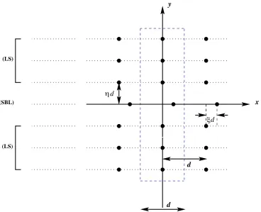
2.1 Stack of gratings consisting of an outer pair of finite nonzero inclusions with radius a and period d, and a central grating of rigid pins. The relative grating separation between consecutive gratings is η, and the relative lateral shift of the central grating is ξ. . . 10 2.2 A plane wave (I) incident on a grating of rigid pins from above. We
show the generic scattered field consisting of reflected and transmitted waves R and T respectively. The lines γ+ and γ− are used to indicate the upper and lower sides of the grating. . . 12 2.3 A two-dimensional lattice composed of particles of the same mass, placed
at equal distances from one another along two lines intersecting at an arbitrary angleθ. . . 14 2.4 (a) Infinite plate with a doubly periodic array of cylindrical voids. (b)
The irreducible Brillouin zone for the doubly periodic square array. . . . 15 2.5 Converged band diagrams for clamped-edge boundary conditions, for
radii (a) a = 0.2 and (b) a = 0.35. Γ, X and M are the vertices of the irreducible part of the Brillouin zone. The inset in (b) shows a magnification of a “collapsed” band. Taken from Poulton et al. (2010). . 16 2.6 Converged band diagrams for free-edge boundary conditions, with
Pois-son ratio ν = 0.3, for radii (a) a= 0.2 and (b) a= 0.35. The bands lie close to those for the Bloch modes of a homogeneous structure. Taken from Poultonet al. (2010). . . 17
2.7 A plane wave (I) incident on a grating of rigid pins from above with angle of incidence θi. We show the diffraction order p =−1 as well as
the zeroth order reflected and transmitted fields. . . 20 2.8 Normalised transmitted energy Ttot, summed over propagating orders
(see equation (3.93)), versus β for a pair of gratings, and normalised reflected energyRtot for a single grating (dashed line) of rigid pins with d= 1. The incident wave is of Helmholtz type, with angle of incidence θi= 30◦. Adapted from Movchan et al. (2009). . . 22
2.9 Normalised reflected energy (efficiency) versus angle of incidence θi for
a single grating of rigid pins for β = 8.0. Solid curve: p = 1, Dashed curve: p=−1. The lines of symmetry for the Littrow angle±23.1225◦ (±0.403565 radians) are shown by the vertical lines. . . 23 2.10 Multiple-beam interference for a transparent plate with thickness hand
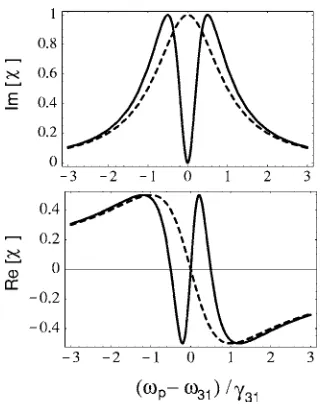
refractive indices n for the ambient medium, and n� for the plate. The angles of incidence and refraction areθ andθ� respectively. . . 25 2.11 Susceptibility as a function of the frequencyωp of the applied field
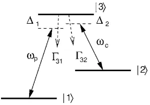
rela-tive to the atomic resonance frequency ω31, for a radiatively broadened two-level system with radiative widthγ31 (dashed line) and an EIT sys-tem with resonant coupling field (solid line): top, imaginary part ofχ(1) characterizing absorption; bottom, real part of χ(1) determining the re-fractive properties of the medium. Taken from Fleischhauer et al. (2005). 28 2.12 Generic system for EIT: lambda-type scheme with probe field of
fre-quency ωp and coupling field of frequency ωc. ∆1 = ω31 − ωp and
∆2 = ω32−ωc denote field detunings from atomic resonances and Γik
radiative decay rates from state|i�to state|k�. Taken from Fleischhauer
et al. (2005). . . 29 2.13 (a) Infinite plate with a doubly periodic array of circular voids. (b) The
central unit cell Ω0,0 containing a circular scatterer. . . 30 2.14 Radius of convergence for multipole expansion. . . 32 2.15 (a) First quadrant of the band surface for the lowest band for the square
array of clamped cylinders of zero radius, with β on the vertical axis. (b) Contours of constantβ for the same surface. The ranges fork0x and
k0y are 0 ≤k0x ≤πd and 0≤k0y ≤πd; the numbers shown along the
intervals Γ X and Γ Y correspond to positions of the points of the grid rather than the values of k0x and k0y. Taken from McPhedran et al.
(2009). . . 37 2.16 Two different views showing the “sandwiching” of the first band (blue)
between the plane wave surfaces shown in red for orders (0,0) and (−1,0) in part(a), and (0,0) and (0,−1) in part (b). . . 38
2.17 Triangle illustrating Graf’s addition theorem for a platonic grating. . . . 40
3.1 Example of a multiple-grating waveguide. The elementary cell is indi-cated by the dashed rectangle. . . 46 3.2 The unit cellΩcontaining a circular scatterer. The boundary ∂Ω is the
union of its constituent parts: ∂Ω =Γ+∪ Γ−∪ Γl∪ Γr∪ C0. We also
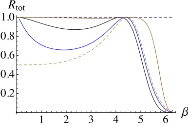
indicate the unit outward normalsn for each part of the boundary. . . . 52 3.3 Normalised reflected energy Rtot versus β for normal incidence for a
single grating of voids with period d = 1 and radius a = 0.1 (brown), a= 0.01 (black), a = 1.0×10⁻⁶ (blue) and the limiting case of a = 0 (dashed). . . 65 3.4 Coordinate systems for the top (x1, y1) and bottom (x2, y2) gratings for a
shifted pair of rigid-pin gratings, and the central line of symmetry (x, y) to which we shift the phase origins of the reflection and transmission matrices. Reflection and transmission matrices for thesth and (s+ 1)th gratings are also shown. . . 66 3.5 (a) Normalised transmitted energyTtot, summed over propagating orders
versusβ for three pairs of gratings, and normalised reflected energyRtot for a single grating (dot-dashed line) of rigid pins. The incident wave is of Helmholtz type with θi = 30◦. Data: d = 1, η = 1. (b) Detail in
the neighbourhood of the transmission resonance for a shift of ξ = 0.4. Dashed lines are used to emphasise the full-power and half-power points. 71 3.6 Enhanced transmission peaks for shifted pairs of gratings with d = 1,
η= 1 andθi= 30◦. Normalised transmitted energyTtotfor propagating orders (zeroth order only) is plotted versusβ for shifts ξ in steps of 0.1 from left to right. The narrowest peaks occur forξ = 0.5 andξ= 0 and these correspond to the highest Q. . . 72 3.7 Triplet of rigid-pin gratings. . . 75 3.8 EDIT effect for a triplet of rigid-pin gratings with the central grating
shifted by ξ= 0.25200 forθi= 30◦. Normalised transmitted energyTtot (curve1, blue) as a function ofβ for the triplet. Curve2(red) represents the total transmission for the outer pair of gratings. . . 76 3.9 Normalised transmitted energy Ttot versus spectral parameter β for a
triplet of rigid pins with α0 = 2.1 in both cases: (a) ηd = 1 ; (b) optimized resonances for a triplet withη∗d= 1.185266. The normalised reflected energy Rtot is shown by the dashed curve. . . 77
4.1 (a) Normalised transmitted energy Ttot versus β for a pair of unshifted rigid-pin gratings (left spike) and for a shift of half the period (right). For both pairs,d= 1,η= 1 andθi = 30◦. Also shown are the normalised
reflected energyRtot versusβ for a single grating (solid green curve close toTtot = 1) and a straight line (dashed) indicating maximum normalised energy of 1. The other two pictures are blow ups of the transmission peaks. These detailed plots illustrate the separation shapes of the Fano resonances. . . 80 4.2 Normalised transmitted energy Ttot, summed over propagating orders
versus β for five pairs of gratings, and normalised reflected energyRtot for a single grating (dashed line) of rigid pins. The incident wave is of Helmholtz type withθi = 27◦, and d= 1,η= 1. The lateral shift values
areξ = 0,0.1,0.2,0.4 and 0.5 from left to right. . . 81 4.3 Normalised transmitted energy Ttot, summed over propagating orders
versus β for five pairs of gratings, and normalised reflected energyRtot for a single grating (dashed line) of rigid pins, with d = 1 and η = 1. The incident wave is of Helmholtz type with (a) θi = 30◦ (b) θi = 29◦
(c)θi = 31◦. The lateral shift values areξ = 0,0.1,0.2,0.4 and 0.5 from
left to right. . . 82 4.4 Total transmittanceTtot (curve1, solid blue) for a pair of rigid-pin
grat-ings and total reflectance Rtot (curve2, dashed olive green) for a single grating of rigid pins as functions ofβ. Data used: (a) η = 1,(b) η= 2. Here L= 0. . . 83 4.5 (a) General incidence for the scattering problem for a symmetric triplet
with a shifted middle grating. I represents the incident plane wave with amplitude 1, andR0 andT0 denote complex amplitudes for zeroth order in reflection and transmission. (b) Anti-symmetric incidence for a stack of three parallel gratings with a shifted middle grating. The modes are odd functions ofy. The amplitudes of the incident waves are 1 above and −1 below the triplet, and Ra and −Ra are the corresponding complex
amplitudes for zeroth order reflection. (c) Symmetric incidence for a shifted triplet. The modes are even functions of y. Here Rs is used
to denote the complex amplitudes for zeroth order reflection for this symmetric case. . . 84
4.6 (a)Ttot versusβ for aligned and shifted triplets for θi= 30◦ and d= 1.
The central spike represents a trapped mode for both geometries. The peak on the right (dotted green) occurs for the triplet with the shifted middle grating (ξ = 0.5) and the peak on the left (solid blue) occurs for the geometry with three aligned gratings with ξ = 0. The grating separation isη = 1 for all consecutive gratings. Also shown isRtot versus β for a single grating and a straight line (dashed) indicating maximum normalised energy of 1. (b)Ttot versusβ in the region of β∗ = 3.61747.
Three geometries are virtually coincident: pair of unshifted gratings with η= 2 (dashed black curve), triplet of aligned gratings (solid blue curve) and triplet with shifted middle grating (ξ = 0.5) with η = 1 between each pair (solid green curve). . . 86 4.7 Transmission resonances for symmetric trapped mode for a triplet with
shifted middle grating ξ = 0.5 (dotted curve), with d = 1 and η = 1 between each grating, and a pair of shifted gratings (ξ= 0.5) withd= 1, η= 1. In both cases,θi = 30◦. . . 87
4.8 Resonantβ∗representing trapped modes for horizontal shiftsξin steps of 0.1 across a single unit period for both shifted pairs (green, dashed), and triplets with a shifted middle grating (blue, solid). For both geometries, θi = 30◦ is considered. We also illustrate the fixed, anti-symmetric
resonance with a horizontal straight line. . . 88 4.9 Ttot versusβ for triplets for θi = 30◦,d= 1,ξ= 0, with various relative
grating separationη. The outer gratings are separated by ηd= 2. The brown curve represents the structure where the central grating is posi-tioned at 35 % of the separation, with respect to the bottom grating. The red curve has the middle grating at 40 %, and the blue curve has its middle grating positioned 45 % into the separation with respect to the bottom of the triplet structure. . . 89 4.10 (a) EDIT effect for a triplet of rigid-pin gratings with the central grating
shifted by ξ= 0.25200 forθi= 30◦. Normalised transmitted energyTtot (blue curve1) as a function ofβ for the triplet. Curve2(red) is Ttot for the outer pair of gratings. (b) Flexural displacement for the outer pair of gratings of rigid pins (η = 2) as a function ofx and y forβ∗ = 3.61747. (c) Flexural displacement for the triplet of rigid-pin gratings (η= 1) as a function ofx and y forβ∗ = 3.61747. . . 90
5.1 Examples of periodic arrays in elastic systems incorporating plates (a) aircraft wings (www.instartupland.com) (b) cable-stayed bridge (Femern A/S, http://buildipedia.com). . . 92
5.2 Stack of gratings consisting of an outer pair of finite nonzero inclusions of radiusaand perioddand a central grating of rigid pins characterised by the relative lateral shift ξ. The relative grating separation between consecutive gratings is η. . . 93 5.3 Normalised reflected energy versus spectral parameter β for θi = 30◦
for a single grating of voids with radius a = 0 using (a) quasi-periodic grating Green’s function and (b) direct summation of grating sums. . . 95 5.4 Normalised reflected (blue) and transmitted (red) energy versus spectral
parameterβforθi = 30◦for a single grating of voids with radiusa= 0.01
using (a) direct summation of grating sums and (b) Twersky accelerated convergence formulae. . . 96 5.5 Pair of gratings consisting of inclusions of finite radius a, with period d
and relative grating separation η. . . 97 5.6 Normalised transmitted energy Ttot (curve 1, solid blue) for a pair of
gratings of inclusions of radius a and normalised reflected energy Rtot (curve2, dashed green) for a single grating of inclusions as functions of β for separationηd= 1 andL= 2. Data used: (a)a= 0.1,(b) a= 0.01. 99 5.7 Normalised transmitted energy Ttot (curve 1, solid blue) for a pair of
rigid-pin gratings and normalised reflected energyRtot (curve2, dashed red) for a single grating of rigid pins as functions ofβ. Data used: η = 2, θi = 30◦, d= 1 and L = 0.The diagram (b) is a blow-up of the sharp
transmission resonance from (a). . . 101 5.8 Normalised reflected energyRtot as a function of β for a single grating
with inclusions of radiusa= 0.1 (with order of truncationL= 2) for the angle of incidence (a) θi = 0◦ (curve 1, red), 7.5◦ (curve 2, blue), 15◦
(curve 3, black) and (b) θi = 30◦ (curve1, green), 25◦ (curve 2, blue),
θi= 20◦ (curve3, red). . . 101
5.9 (a) Triplet consisting of three identical gratings of inclusions with nonzero radiusa; (b) triplet consisting of a central grating of inclusions of nonzero radiusa, surrounded by a pair of rigid-pin gratings; (c) triplet consisting of a pair of gratings with inclusions of nonzero radius a surrounding a grating of rigid pins. . . 102 5.10 Normalised transmitted energyTtot (curve1, solid blue) as a function of
βfor normal incidence for a triplet of gratings of inclusions witha= 0.02, ηd= 1 andL= 2. Curve2(dashed) represents normalised reflectedRtot for a single grating of such scatterers: (a) aligned gratings, ξ = 0; (b) shifted central grating withξ = 0.2. . . 103
5.11 (a) Normalised transmitted energy Ttot as a function ofβ for a triplet of unshifted gratings of rigid inclusions witha= 0.01,ηd= 1, forθi= 30◦.
Field plots for transmission resonances: (b) a symmetric mode with β∗(1) = 3.819908; (c) an anti-symmetric mode withβ∗(2) = 3.93678. . . . 104 5.12 Normalised transmitted energy Ttot as a function of β for normal
inci-dence for a symmetric triplet with (a)a= 0 (normalised reflected energy Rtot for a single grating of zero-radius scatterers is shown by the dashed curve) (b) a= 0.15 and (c)a= 0.20 for the central grating. Hereξ = 0, ηd= 1, andL= 2. . . 105 5.13 Flexural displacement as a function ofxandyfor (a) an anti-symmetric
mode (β∗ = 3.9995073) and (b) a symmetric mode (β∗ = 4.041664). Data used: central grating inclusions with a= 0.1,θi = 18◦ and ηd= 1. 107
5.14 Normalised transmitted energy Ttot as a function of β: (a) for a triplet consisting of an outer pair of gratings with a = 0.1 and the central grating of rigid pins (ηd = 1); (b) for the outer pair of gratings with a= 0.1 and η=d= 2. Data used: θi= 15◦,L= 2. . . 107
5.15 Flexural displacement as a function of x and y for a triplet consist-ing of an outer pair of gratconsist-ings with inclusions of radius a = 0.1 and a central unshifted rigid-pin grating, for an angle of incidence of 15◦. (a) Anti-symmetric mode (β∗ = 4.011852); (b) symmetric mode (β∗ = 4.0496094). Data: ηd= 1 and L= 2. . . 108 5.16 Normalised transmitted energy Ttot as a function of β for two shifted
triplets, ξ = 0.25 (solid blue) and ξ = 0.5 (solid red), containing a central grating of rigid pins (ηd = 1). (a) Angle of incidence θi = 15◦,
outer scatterer radiusa= 0.1; (b)θi= 20◦, a= 0.085. . . 109
5.17 EDIT: normalised transmitted energy Ttot (solid black curve) as a func-tion of β for a shifted rigid-pin triplet with ξ = 0.25200 for θi = 30◦.
The two peaks represent the transmission resonances for the outer pair (solid blue) and the inner pair (dashed). . . 109 5.18 Normalised transmitted energyTtot (curve1, solid blue) as a function of
β for a triplet with a shifted central grating of rigid pins and the outer pair of gratings of inclusions of radius a = 0.01. Curve 2 (solid red) represents the total transmittance for the outer pair of gratings. Data used: (a)ξ = 0.3112,θi = 27◦. (b)ξ = 0.23265, θi = 26◦. . . 110
5.19 (a) Flexural displacement as a function ofx and y for a pair of gratings consisting of inclusions of radiusa= 0.01 with grating separationηd= 2 forβ∗ = 3.748779850. (b) Flexural displacement as a function ofx and y for a triplet with a shifted central grating of rigid pins (ξ = 0.23265) and the outer pair of gratings consisting of inclusions of radiusa= 0.01 forβ∗ = 3.748779784, ηd= 1. Data: θi = 26◦. . . 111
5.20 Normalised transmitted energy Ttot as a function ofβ for a triplet with a shifted central grating of finite radius inclusions with a= 0.0035, and an outer pair of gratings of inclusions of radiusa= 0.01,θi = 26◦. Data
used: (a)ξ = 0.4 (red curve),ξ = 0.42 (blue curve); (b)ξ = 0.45556. . 112
6.1 Example of a triple grating waveguide. The elementary cell is indicated by the dashed rectangle. . . 115 6.2 Contours for logarithm of modulus ofM11−M13(solid), and of 2M12M21−
M11(M11+M13) (dashed) for a shifted three-grating stack of rigid pins (ξ = 0.25200, d= 1), as a function of α0 and β. The circle corresponds to (α0, β) = (1.808735,3.61747). . . 119 6.3 Surface plot of the logarithm of the modulus of (a)M11−M13(odd mode)
(b) 2M12M21−M11(M11+M13) (even mode) for the shifted three grating stack of rigid pins (ξ= 0.25200, d= 1), as a function ofα0 and β. . . . 120 6.4 Contours for logarithm of modulus ofM11−M13 (solid), and of 2M122 =
M11(M11+M13) (dashed) for an aligned three grating stack of rigid pins (d = 1, ξ = 0), as a function of α0 and β. The circle corresponds to (α0, β) = (1.66451,3.596951). . . 122 6.5 Surface plot of the logarithm of modulus of M11−M13 for an aligned
three grating stack of rigid pins (d= 1, ξ= 0), as a function ofα0 and β. 122 6.6 Surface plot of the logarithm of modulus of M11−M13 for an aligned
three grating stack of rigid pins (d= 1, ξ = 0), as a function ofα0 and β, giving the odd mode trajectory in the vicinity of the light line. . . 123 6.7 (a) Normalised transmitted energyTtotversus spectral parameterβfor a
triplet of rigid pins (d= 1,ξ= 0) withα0 = 2.1 (blue curve / right-hand pair), α0 = 2.3 (black curve / central pair) and α0 = 2.5 (red curve / left-hand pair). The corresponding curves for the reflectance of a single grating of rigid pins are dashed. (b) Log|p(v)|from equation (6.32) for α0 = 2.1. . . 124 6.8 (a) Log|p(vA)| with α0 = 2.1 (d = 1, ξ = 0), 3.4 ≤ β ≤ 3.6 and
−2≤A≤2. (b) Log|p(v)|versus β forvT = 1/√6(1,2,1). . . 125
6.9 Dispersion diagram for a waveguide consisting of an unshifted triplet with the horizontal axis representing α0 in the range 0.5≤α0 ≤3, and β on the vertical axis in the range 3 ≤ β ≤ 3.8. The dashed curve represents the odd modes, and the blue curve, the even modes. . . 126 6.10 Normalised transmitted energy Ttot versus spectral parameter β for an
unshifted triplet (ξ = 0) of rigid pins with α0 = 2.1 and d= 1 and: (a) η= 1 ; (b) optimized resonances for a triplet with η∗= 1.185266. . . . 127 6.11 β versus α0 for odd (red) and even (blue) modes for optimized grating
separationη∗ for unshifted triplets (Data from Table 6.1). . . 129 6.12 The logarithm of the modulus of the determinant of the matrix Mas a
function of β forθi = 60◦, d= 1, η∗ = 2.131958 (a) ξ= 0 (b)ξ = 0.2476. 129
6.13 Optimized EDIT withθi = 60◦,η∗ = 2.13196 andξ= 0.2476 withd= 1.
In (b), we replace β by 2.94715999 + ∆β, because the transmission minimum is so narrow. . . 130 6.14 Normalised transmitted energy Ttot versus spectral parameter β for a
triplet of rigid pins with d = 1, η = 1.00866 and θi = 30◦ for various
shifts of the central grating: (a) ξ = 0.22 (solid curve), ξ = 0.23 (dot-dashed curve) and ξ = 0.24 (dashed curve) (b) ξ = 0.2285 (dot-dashed curve), ξ= 0.2287 (solid curve) and ξ= 0.2288 (dashed curve). . . 130 6.15 Normalised transmitted energy Ttot versus spectral parameter β for a
triplet of rigid pins with d = 1 and θi = 1◦ for the optimized grating
separation η = 0.705679367 and the EDIT shift of the central grating ξ= 0.165868. . . 131
A.1 (a) An example of a typical K-type grating sum which can be evaluated directly because of its exponential convergence. (b) An example of a Hankel-type grating sum which demonstrates why Twersky’s alternative representation is valuable. . . 136 A.2 (a) Real part of Hankel function grating sum evaluated by direct
summa-tion of 50 terms forβ = 3.6 for normal incidence. (b) Real part of Hankel function grating sum evaluated using Twersky accelerated convergence formulae for 50 terms for β= 3.6 for normal incidence. . . 138 A.3 (a) Imaginary part of Hankel function grating sum evaluated by direct
summation of 50 terms for β = 3.6 for normal incidence. (b) Imaginary part of Hankel function grating sum evaluated using Twersky accelerated convergence formulae for 50 terms forβ = 3.6 for normal incidence. . . . 139
A.4 Normalised reflected energy Rtot (blue curve) and transmitted energy Ttot (red) versus spectral parameter β for normal incidence for a single grating with a= 0.1 in the range 0.1 < β < 2π for propagating orders (zeroth order only in this range). (a) grating sums evaluated by direct summation and (b) Twersky accelerated convergence formulae. . . 140
Acknowledgements
I would like to thank the Duncan Norman Charitable Trust whose financial support through the Duncan Norman Research Scholarship has enabled me to undertake my PhD in applied mathematics at the University of Liverpool. This made it possible for me to continue my studies under the supervision of Professors Alexander and Natasha Movchan, with whom I worked during my MSc.
It has been both a tremendous privilege and a great pleasure to work with them. Their dedication, encouragement, numerous insights and support have been invaluable over the last few years. I would also like to thank Sasha for encouraging me to return to academia to study for a PhD after a spell away playing chess professionally, and for his and Natasha’s understanding and support in allowing me to play several tournaments during the last four years.
I owe a huge amount of gratitude to Ross McPhedran, the co-author of all of our published papers. I feel extremely fortunate to have worked with a great mathematical physicist and a great man over the last few years, and I hope to continue our collab-orations in the future. I should also like to mention Daniel Colquitt and Mike Nieves who have always been ready to help me with both advice and more technical matters. The dedication, approachability and enthusiasm of the Mathematical Sciences De-partment staff hugely influenced my decision to pursue an academic career so I was very keen to continue my studies here. I would like to give a special mention to ¨Ozg¨ur Selsil and Peter Giblin, whose sage advice and support I have regularly sought over the last few years. I would also like to thank Joanna Seed, Shirley Farrell, Ingrid Harper, Lyn Hughes and Rebecca Morton who have provided me with the answer on every occasion that I had a question throughout my studies.
I would like to thank my fellow post-graduate student friends, of whom there are too many to mention all by name. I would also like to mention my Italian friends Giorgio Carta (my office-mate), Luigi Cabras, Michele Brun and Felice Giaccu who have taught me so much about their language, culture, food and most importantly friendship over the last few years. Grazie mille!
And of course I would like to thank my family for their unconditional love and support. My parents Mike and Sandy, and my brothers and sister Gareth, Toby and Mandy, have all shown tremendous understanding and patience during my PhD studies.
List of Publications
1. Haslinger, S. G., Movchan, N. V., Movchan, A. B. & McPhedran, R. C. (2011), Wave localisation in structured elastic plates, Proc. Int. Conf. on Vibration Problems(ed. N´aprstek et al.), 737-743, Springer Proceedings in Physics 139.
2. Haslinger, S. G., Movchan, N. V., Movchan, A. B. & McPhedran, R. C. (2012) Transmission, trapping and filtering of waves in periodically constrained elastic plates. Proc. R. Soc. A468, 76-93.
3. Haslinger S. G., McPhedran R. C., Movchan N. V. & Movchan A. B. (2013) Localisation near defects and filtering of flexural waves in structured plates. Int. J. Fract. 184, 25-41.
4. Haslinger S. G., McPhedran R. C., Movchan N. V. & Movchan A. B. (2013) Struc-tured interfaces for flexural waves - trapped modes and transmission resonances.
Journal of Physics: Conference Series451 012024.
5. Haslinger S. G., Movchan A. B., Movchan N. V. & McPhedran R. C. (2014) Symmetry and resonant modes in platonic grating stacks. Waves in Random and Complex Media(published online February 2014).
DOI: 10.1080/17455030.2014.884733
Chapter 1
Introduction and background
In this thesis we consider thin structured plates that contain an interaction region consisting of a finite number of periodic gratings, and our particular interest is in the localisation of flexural waves within the grating structure. Many elastic systems such as aircraft, long bridges and reinforced roads encompass periodic arrangements of inclusions, voids and masses. These structures are frequently subjected to stress concentrations and therefore the study of the resonant action of incident flexural waves within our structured plates has applications in engineering, in addition to its intrinsic interest.
We place this work in the relatively new field of platonics, which concerns the prop-agation of elastic waves, in the form of flexural bending waves, through thin structured plates. The term platonic crystal was first used by McPhedranet al. (2009), and was defined as “any structured system that is governed by the biharmonic plate equation”. The key words here are structured and plate, since the first half of the word platonic is derived directly from plate, and the second half alludes to the analogy of the structured periodic system with photonic and phononic crystals.
Since the 1980’s, there has been substantial interest in problems concerned with wave properties in doubly periodic structures among mathematicians, engineers and physicists. The majority of the research is concerned with electromagnetism and ad-dresses Maxwell’s system and the Helmholtz equation, so it is referred to as the photonic band-gap problem. Photonic crystals are designed to control the propagation of light through periodic media with varying refractive indices. The books on the subject by Joannopouloset al. (2008) and Sakoda (2005) provide excellent coverage of the present state of the field. The extensive body of literature directed to the study of photon-ics was a primary motivation in considering similar periodic problems for alternative media.
One such smaller body of the literature concerns acoustic and elastodynamic waves, where the properties of solutions of the Lam´e system for structured media are inves-tigated. This field is referred to as the phononic band-gap problem. The recent book
by Deymier (2013) provides an up-to-date overview of phononic crystals and acoustic metamaterials. An excellent collection of references to results in both of these fields may be found in the online bibliography (The Photonic and Sonic Band Gap Bibliog-raphy, 2008). A combination of the exponential growth of the work, and competition from Google Scholar, influenced the editor Jonathan Dowling to cease updating the website from 2008.
A recent search for photonic and phononic crystal publications indicated that there have been around 40,000 papers dealing with photonic crystals compared with around 400 for phononic papers. In contrast, the topic we discuss here has received very little prior attention, numbering fewer than 20 papers at the time of writing. It concerns the vibrational modes of thin structured elastic plates governed by an equation involving the biharmonic operator. It is distinguished from the electromagnetic and acoustic cases by the important fact that the Green’s function for this operator is non-singular at the source point, whereas the Green’s function for the two-dimensional Helmholtz operator diverges logarithmically.
One essential tool in understanding the behaviour of waves in photonic crystals and related systems is that of Bloch waves. These provide a basis set of functions suitable for expanding any wave within such structures. Another crucial tool implemented throughout this work is the Rayleigh method for which field quantities are represented by multipole expansions. The underlying principle of such a multipole method is the application of a field identity (Rayleigh identity) that, by the use of lattice sums (see Borwein et al. 2013), relates the regular field in the vicinity of any scatterer to the fields radiated by the other scatterers and external sources (Rayleigh 1892).
We are interested in periodic arrays embedded in thin elastic plates. The simplest periodic array is a diffraction grating, which contains an infinite number of equally spaced scatterers positioned along a line. A diffraction grating is used to scatter incident plane waves (Born & Wolf 1959). Two crucial concepts imported from classical optics are directly applicable here; quasi-periodicity and the Fraunhofer diffraction grating equation. The dispersive properties of electromagnetic diffraction gratings (Born & Wolf 1959) have analogous counterparts in platonic diffraction grating arrays used to scatter and disperse flexural waves.
Diffraction grating theory is very relevant for the analysis of wave propagation through two-dimensional periodic structures since any doubly periodic array may be regarded as an infinite stack of gratings. An alternative treatment uses Bloch-Floquet theory to determine the dispersion relation for the platonic crystal. Both methods generate spectral band diagrams and reveal when the propagation of the flexural waves is supported through a two-dimensional array.
There is much scope regarding both the nature and geometry of possible scatterers. We primarily analyse circular scatterers with clamped boundaries, but our method is
equally valid for inclusions or point masses. Similarly any smooth geometrical shapes may be used, but we favour circular boundaries which support an elegant analytic method of solution. The boundary conditions imposed on the edges of the scatterers may range from fully clamped to free edge, which allow for free bending of the plate. A special case where the radius of the clamped holes tends to zero, gives us a periodically pinned plate.
One of the earliest papers on a two-dimensional periodic array, by Movchan et al.
(2007), addressed the spectral problem for a thin elastic plate containing a square array of circular holes or rigid stationary inclusions. Platonic band diagrams were obtained, and it was shown that in the case of a free boundary, the band diagram tends to that of the unstructured elastic plate as the radius of cylinders tends to zero. However for clamped boundaries it was shown that the zero-radius case corresponds to a complete platonic band gap running from zero frequency up to a finite value that can be evaluated simply. This striking result means that the flexural wave properties of gratings made of fixed pins having zero radius are non-trivial, and such gratings when stacked together can give good filtering action, an effect that can be accurately described using a theory that is both elegant and easily understood.
The work done by Evans & Porter (2007) emphasised the role of trapped modes within these grating systems. This followed on from related research on supported plates (Evans & Meylan 2005 and Evans & Porter 2006) where pinned elastic plates floating on water were investigated. We restrict our attention to biharmonic plates containing periodic arrays, with the emphasis on the importance of evanescent modes. Konenkov (1960, 1964) considered the case of a single circular inclusion using mul-tipole techniques. The additional complexity of one- and two-dimensional arrays being embedded within the plates was investigated later. Some early references are Kouzov & Lukyanov (1976) where a doubly periodic array of pins and point masses were con-sidered for plates, interacting with ambient sound waves in the context of modelling acoustically-absorbing sandwich structures. Norris and Vemula provided comprehen-sive coverage of circular inhomogeneities for both Kirchhoff-Love (1995) and Mindlin (1997) theories. The work by Evans & Porter (2007) and Movchanet al. (2007) was carried out independently later, and emphasised the elegance and simplicity of the method of solution for pinned plates.
The work was advanced in several papers by Movchanet al. (2009, 2011), McPhe-dran et al. (2009) and Poulton et al. (2010, 2012). This included the analysis of finite stacks of gratings, wave trapping, nonzero radius of scatterers and a comparison of results for Kirchhoff-Love and Mindlin plates. The filtering effects associated with the trapping of waves within grating systems exhibit optical-type behaviour linked to Fabry-P´erot theory.
Other related work on platonic crystals has been the engineering of structures that
exhibit complex diffraction behaviour. Farhat et al. (2009, 2010a,b) theoretically demonstrated negative refraction in thin plates, whereby a point source is refocused around a finite disk. Recent papers by Smith et al. (2011-2013) observed negative refraction properties and flexural lensing. A recent example of experimental cloaking was successfully carried out by Stengeret al. (2009) who based their approach on the theory of Farhatet al. (2009). A cloak in the form of a concentric ring was designed to surround a single clamped circular scatterer, and cloaking was observed for a wide frequency range of 200-400 Hz.
This thesis considers various structured regions that are used to filter flexural (out-of-plane displacement) plane waves. The main body of work incorporates three papers. The first concerns a platonic crystal containing a finite number of gratings stacked above one another. The elegance and simplicity of the analytic solution for a grating of rigid pins arises from the linearity of the biharmonic plate equation. This linearity allows the scattered field to be expressed as a superposition of Helmholtz and modified Helmholtz waves (see Section 2.2). A related expansion involving the Green’s function of the plate was used by Evans & Porter (2007).
We develop a recurrence algorithm for constructing the reflection and transmission matrices required to characterise the filtering of plane waves by the structured system with shifted gratings. Similar recurrence procedures have been extensively used in electromagnetism. We refer the reader to the overview by Botten et al. (2003), where material on the accompanying lattice sums is instructive, and to the papers by Botten
et al. (2001) and Platts et al. (2002, 2003) amongst others. An early example for a platonic grating system is the paper by Movchan et al. (2009). In Chapter 3 we go through the method of solution in detail, both for an incident plane wave scattering problem, and the treatment of the system as a waveguide.
The variation of the grating system parameters demonstrates several interesting filtering properties related to trapped modes and transmission resonances. The effect of resonant transmission is illustrated in Fig. 1.1 where the field plot shows the flexural displacement inside a stack of three gratings of rigid pins, and the plane wave outside the stack. The plane wave appears for this case to be virtually unperturbed for the chosen frequency. However we show that controlled lateral shifts of three gratings can give rise to a transmission peak with a sharp central suppression region, akin to the phenomenon ofelectromagnetic induced transparency(EIT), a quantum-mechanical effect which arises in three-level atomic systems (Fleischhaueret al. 2005).
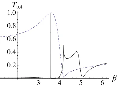
We discuss EIT in Section 2.4.5 but the characteristic curve of absorption versus frequency in Fig. 2.11 bears a striking resemblance to the transmitted energy curve for a three-grating stack shown in Fig. 1.2(b), where symmetric and anti-symmetric modes coincide, discussed in detail in Chapters 4 to 6. Destructive interference results and the total transmitted energy is negligibly small at this minimum and we therefore term
d
d d
d
y
e i
d
x
(a) (b)
y x
Figure 1.1: (a) Triplet of aligned rigid-pin gratings with perioddand relative grating separationη = 1. The angle of incidence isθi. (b) Flexural displacement plotted as
a function of x and y for the transmission resonance associated with a symmetric trapped mode for θi= 30◦ for the grating stack illustrated in (a).
the platonic effect Elasto-Dynamically Inhibited Transmission (EDIT).
EDIT features strongly in our published papers (see Haslinger et al. 2012, 2013, 2014) but there are analogies with EIT in other fields. A recent paper by Lin et al. (2009) described EIT-like effects linked to optomechanical interference for nano-optomechanical structures (NOMS). The authors refer to induced mechanical trans-parency (IMT) where two modes, one optically bright and the other optically dark (akin to our symmetric and anti-symmetric modes) coincide. The destructive interfer-ence suppresses excitation of the mechanical system.
Recent literature in metamaterials also refer to EIT analogues. These include the papers by Zhanget al. (2008), Papasimakiset al. (2008) and Tassinet al. (2009). Liu
et al. (2009) consider a planar metamaterial analogue of EIT for plasmonic sensing, which involves a shift control parameter similar to the one we employ for the central grating in a finite grating stack. The structural asymmetry is an important factor in coupling the modes to induce the interference effects that underpin the EIT-like effect. In our second paper described in Chapter 5, we studied the localisation of flexural waves within shifted grating systems composed of clamped holes or rigid inclusions of finite radius in the structured plate. The effect of the finite value of the radius on the dynamic localisation was analysed for the range of frequencies where only zeroth grating orders propagate. Poulton et al. (2010) presented a thorough coverage of nonzero-radius gratings for the doubly periodic square array. The structure of the resonant modes within gratings of inclusions is of special interest, since EDIT is dependent on the coincidence of symmetric and anti-symmetric modes. The increased radius of the voids makes it necessary to carefully take into account higher-order multipole terms characterising the scattered field, and associated higher-order lattice sums. Lattice
3.56 3.57 3.58 3.59 3.60 3.61 3.62
Β
0.20.4 0.6 0.8 1.0
T
tot3.615 3.616 3.617 3.618 3.619 3.620
Β
0.20.4 0.6 0.8 1.0
T
totFigure 1.2: Normalised transmitted energyTtotversus spectral parameterβ for a triplet of rigid pins with θi = 30◦, d = 1, η1 = η2 = 1 in both cases and: (a) ξ = 0 ; (b) ξ= 0.25200. The parameter ξ represents relative lateral shift of the central grating.
sums (see Borweinet al. 2013) are an essential aspect of multipole methods for periodic systems, and are sums of terms evaluated at each point of the array’s structure. Their evaluation is both important and subtle, with complications arising from the definition of conditionally convergent series.
In the culminating third paper described in Chapter 6, the grating stack is con-sidered as a structured waveguide for trapped modes. For a stack of rigid pins, a quasi-periodic Green’s function is employed to derive the dispersion equation for Bloch waves in such a waveguide. The dispersion equation solutions are displayed graphi-cally in band diagrams. A connection is established with the transmission problem by identifying parameters of the grating stack and of the incident wave, to generate a transmission resonance linked to a trapped Bloch wave within the structured waveguide. We classify the even and odd classes of modes, and we show how the EDIT interaction may be steered over a wide range of frequencies and angles, using a strategy in which the single-grating reflectance is kept high. In this way, the quality factors of the even and odd resonances may be kept large.
The filtering effects we have discovered have several potential applications in wave filtering. Surface acoustic waves (SAW) are acoustic waves travelling along the surface of an elastic material, with an amplitude that typically decays exponentially with depth into the substrate. In seismology for example, surface acoustic waves travelling along the Earth’s surface are often the most destructive type of seismic wave produced by earthquakes. There may be the possibility of fabricating switches linked to the EDIT effect where a peak in transmission is suppressed by finely tuning the lateral shift control. The resonances which provide the EDIT phenomenon are, as we show in Chapters 4 to 6, extremely narrow and may thus find application in flexural wave filters.
Before describing the method of solution, which incorporates several complex tech-niques including multipoles, Rayleigh method, Graf’s addition theorem, grating sums
and a recurrence procedure, we introduce the important underlying concepts. This includes a brief summary of the important ideas that we use from the classical optical theory of gratings. We also outline the derivation of the quasi-periodic Green’s function for a single grating of clamped circular voids and introduce the lattice sums used to characterise the interaction of the flexural waves with the periodic structured interface. Lattice sums are needed both for the Helmholtz and modified Helmholtz equations. We conclude with a chapter summarising the overall findings of our work, and discuss potential applications and future continuation of the research.
Chapter 2
Underlying theory
2.1
Governing equation
The underlying equation of this thesis is the biharmonic plate equation. It is derived using the Kirchhoff-Love plate theory, which may be viewed as the two-dimensional analogue of the Euler-Bernoulli beam equation. The basic hypothesis of Euler-Bernoulli beam theory is that plane cross-sections initially perpendicular to the axis of the beam remain plane and perpendicular to the neutral axis during bending. This assumption implies that the longitudinal strains vary linearly across the depth of the beam and, for elastic behaviour, the beam’s neutral axis passes through the centroid of the cross-section (Graff 1975). Euler-Bernoulli theory yields a dispersive system unlike the wave equation for strings.
For the two-dimensional plate, the main kinematic assumptions are that
- straight lines normal to the surface remain straight, and normal to the mid-surface after deformation;
- thickness of plate does not change during deformation. Graff (1975) provides a derivation based on moments and forces, and an alternative method using asymptotics is sketched by Movchan & Movchan (1995).
The standard Kirchhoff plate equation of motion is
D∆2w(x;t) + ρh∂ 2w
∂t2 (x;t) = 0, (2.1)
wherewis the out-of-plane displacement,x= (x, y),ρis the mass density of the plate, h is its thickness and D is the flexural rigidity of the plate, D = Eh3/(12(1−ν2)), where the physical parameters of the elastic material are the Young’s modulusE and the Poisson ratioν. We assume time-harmonic vibrationsw(x;t) =W(x) sin(ωt) where W is the amplitude andωis the angular frequency. Substituting this into equation (2.1) we obtain an equation satisfied by the amplitudeW(x):
∆2W(x)−β4W(x) = 0, (2.2)
withβ2 =ω�ρh/D. The spectral parameterβ has dimension 1/Lwith unitsm−1 and therefore may be considered as a wavenumber. This equation is widely known as the biharmonic plate equation.
Kirchhoff-Love plate theory is concerned with the analysis of out-of-plane bending waves, and contributes little with respect to the propagation of in-plane elastic waves. The flexural bending waves are fundamentally different in character from compressional acoustic or electromagnetic waves. They account for the lowest frequency waveguide mode for elastic waves, and they are dispersive.
The solution to the Kirchhoff-Love, or biharmonic, plate equation depends on the geometry of the plate and the boundary conditions. For the scattering problems that we consider within this thesis, we assume an infinitely large plate containing circular inclusions. For strong filtering effects, clamped boundary conditions provide the best examples. Therefore these are used throughout the thesis, the details of which are given in Section 2.1.1.
Kirchhoff theory is the classical approach and is usually applicable for the case of thin plates where the thickness h is smaller than the wavelength λ of flexural out-of-plane displacements. Mindlin theory is the alternative, and Movchan et al. (2011) conducted a comparative analysis of the two plate models for the dynamic response of platonic structures. In this thesis, we consider classical Kirchhoff theory. For the application of Mindlin theory to elastic plates incorporating cylindrical cavities or in-clusions, we refer the reader to the work by Vermula & Norris (1995, 1997) and to Movchan et al. (2011), as well as earlier research carried out by Pao & Chao (1964) and Lu (1966).
2.1.1 Structured interaction region
We consider an infinite thin elastic plate with an internal structure which consists of a finite number of parallel gratings. Our model allows for the gratings to consist of cylin-drical inclusions whose cross-sections are of arbitrary smooth shape or size. Here we concentrate on circular voids of finite radius with clamped boundaries, and the limiting case of the radius tending to zero, corresponding to a pinned point. We demonstrate that the periodically structured grating stack supports sharp transmission resonances for low-frequency flexural vibrations. The resonances arise from the interaction with the plane wave, characterised by the angle of incidenceθi and spectral parameter β.
We show one such configuration in Fig. 2.1, where the outer pair of the triplet consists of clamped-edge voids or rigid inclusions with a finite radius a, whilst the central grating contains pinned points. The other parameters are the angle of incidence θi, the period of the gratingsdand the relative grating separation η. We also indicate
the scattered field. An important additional parameter is the relative shift of the central grating denoted by ξ, which is crucial for supporting a filtering effect similar
!"# $#
%# &#
&#
'#
(#
)#
*#
+,#
-# '#
'# #'#
Figure 2.1: Stack of gratings consisting of an outer pair of finite nonzero inclusions with radius a and period d, and a central grating of rigid pins. The relative grating separation between consecutive gratings isη, and the relative lateral shift of the central grating is ξ.
to electromagnetically induced transparency (EIT). We term this Elasto-Dynamically Inhibited Transmission (EDIT). This novel phenomenon for elasticity problems was first observed by Haslinger et al. (2012, 2013, 2014). It is characterised by a resonant peak in transmission being cut in two by a resonant dip with an extremely high quality factor. We discuss it in more detail in Section 2.4.5 and Chapters 4 to 6.
The two most natural types of boundary conditions to consider are clamped and free edge on the circular boundary of the scatterers in Fig. 2.1. Clamped boundaries provide the best conditions for strong filtering effects.
Dirichlet clamped edge conditions are
W � � � � �
r=a
= 0, ∂W ∂r
� � � � �
r=a
= 0. (2.3)
In particular, when the radiusa tends to zero we retrieve the case of fixed pins.
Our results arise from modelling the propagation of flexural waves through the structured grating stack. We consider plane waves which propagate freely through the homogeneous material until they reach the stack of gratings whereupon they are reflected and transmitted. We use plane wave representations, where both propagating and evanescent orders are taken into account.
2.2
Plane wave representations of scattered waves
The biharmonic plate equation (2.2) may be written in its factorised form:
∆2W(x)−β4W(x) = (∆+β2)(∆−β2)W = 0, (2.4) whereβ2 =ω�ρh/D with the physical parameters being defined as in Section 2.1.
Hence W is the superposition of two types of wave, one satisfying the Helmholtz equation and the other satisfying the modified Helmholtz equation:
(∆+β2)WH = 0 and (∆−β2)WM = 0. (2.5)
An important aspect of the physics of the problem is that WH contains both
propa-gating and evanescent waves, while WM consists entirely of evanescent waves (decay
exponentially). The incident field is represented by plane waves of two types:
1. Propagating (or evanescent) solution of the Helmholtz equation
Wi, H(x) =
1
�
|χ0|exp{i(α0x−χ0y)}, (2.6) whereα20+χ20 =β2. Hereχ0 is real and positive for a propagating solution. For the evanescent solution,χ0 is pure imaginary, with positive imaginary part. 2. Evanescent solution of the modified Helmholtz equation
Wi, M(x) =
1
�
|χˆ0|exp{i(α0x−χˆ0y)}, (2.7) whereα02+ ˆχ20 =−β2, χˆ0 =iτ0, τ0 >0.
As in Movchan et al. (2009), we use plane wave series expansions to describe the reflected and transmitted waves. We consider a single grating lying on the horizontal x-axis. We define two straight lines γ+ and γ− parallel to the grating, placed at an arbitrary distance either side of thex-axis (see Fig. 2.2). We use these lines to represent the upper and lower “sides” of the grating. This notation is important for the recurrence algorithm we employ to build a stack of multiple gratings, since we must distinguish between the directions of the waves as they hit the grating. Throughout this thesis, we use the superscript “+” to denote waves from above the grating, and the superscript “−” to label waves arriving at the grating from below.
If we consider an incident field, of Helmholtz or modified Helmholtz type defined using representations (2.6) or (2.7), hitting a grating, we may represent the total field by
W(x) =Wi(x) +Ws, H(x) +Ws, M(x), (2.8)
where the scattered field Ws(x) has been split into two parts. Each of these parts
consists of reflected and transmitted fields, the reflected waves being present on γ+ and the transmitted waves emanating from γ−. The plane wave expansions are given below:
x y
!
< a a
T R
d
[image:29.612.213.423.73.321.2]I
Figure 2.2: A plane wave (I) incident on a grating of rigid pins from above. We show the generic scattered field consisting of reflected and transmitted wavesRand T respectively. The linesγ+ andγ− are used to indicate the upper and lower sides
of the grating.
Plane wave expansions for scattered field
1. Onγ+, we have reflected waves of Helmholtz and modified Helmholtz type: Ws, H(x) =
�
p
Rp
� |χp|
exp{i(αpx+χpy)}, αp =α0+ 2πp
d , α 2
p+χ2p=β2, (2.9)
where the integer p describing the order of the scattered field, covers an infinite range which can be divided into two sets, one containing propagating waves for which χp are real, and the other comprises evanescent waves, for which χp are
pure imaginary with positive imaginary part. We discuss the concept of diffraction orders in more detail in Section 2.4 when we consider the diffraction grating of classical optics.
We have a similar expression for the evanescent waves arising from the modified Helmholtz equation:
Ws, M(x) =
�
p
ˆ Rp
� |χˆp|
exp{i(αpx+ ˆχpy)}, α2p+ ˆχ2p =−β2, χˆp =iτp, τp >0.
(2.10)
2. Onγ−, we have transmitted waves of Helmholtz and modified Helmholtz type:
Ws, H(x) =
�
p
Tp
� |χp|
exp{i(αpx−χpy)}, α2p+χ2p=β2, (2.11)
and
Ws, M(x) =
�
p
ˆ Tp
� |χˆp|
exp{i(αpx−χˆpy)}, α2p+ ˆχ2p=−β2, χˆp=iτp, τp >0.
(2.12)
These plane wave representations are valid outside of the strip bounded by the linesγ+ and γ− in Fig. 2.2, but we use cylindrical multipole expansions within this strip (see Section 2.5.2).
2.3
Quasi-periodicity conditions
The periodicity of platonic gratings in the horizontal direction imposes a quasi-periodicity condition (Bloch-Floquet condition) on plane waves that interact with the grating. A quasi-periodic function is similar to a periodic functionφ(x+d) =φ(x), but there is a change in phase across each period d:
f(x+d) =eiκxdf(x),
where realκx is called the Bloch factor. So for a quasi-periodic functionf, the modulus
|f|is periodic since|eiκxd|= 1.
Quasi-periodic representations arise in problems involving periodic arrays and are extremely convenient since they allow a reduction of the domain to a single period for a grating, or an elementary cell for a two-dimensional array. In this latter case, the elementary cell containing the origin is called the primitive or Wigner-Seitz cell. The corresponding quasi-periodicity condition is
W(x+Rp) =W(x)eiκ.Rp, (2.13)
withx = (x, y) and Rp the array vector which locates the position of each individual scatterer within the array. For example, for a square array we have Rp = (md, nd)
wherem, n are integers. In equation (2.13), κdenotes the Bloch vector, and solutions of (2.13) which satisfy the condition are called Bloch waves, or occasionally Floquet-Bloch waves.
The platonic grating is a particular case whereby the displacement fieldW satisfies the Bloch quasi-periodicity condition along the horizontalx-axis:
W(x+pde(1)) =W(x)eiα0pd. (2.14)
Herepis an integer,dis the period, andα0 =βsinθi, whereθiis the angle of incidence
(see Fig. 2.1).
The two-dimensional arrays we primarily consider consist of an integer number N of platonic gratings, so equation (2.14) is fundamental to our treatment. However in
b
d
x y
d
’ ’ 2
d
1
1
1 2
2
e /<e
[image:31.612.210.431.70.300.2]d b
Figure 2.3: A two-dimensional lattice composed of particles of the same mass, placed at equal distances from one another along two lines intersecting at an arbitrary angle θ.
the limit as N → ∞, the structure tends towards the infinite doubly periodic array. Comparison is subsequently made between the two approaches so we introduce the ideas of direct and reciprocal lattice vectors and Brillouin zones for two-dimensional arrays in Section 2.3.1.
Platonic crystals are fundamentally periodic arrays and have many things in com-mon with lattice structures. Therefore several concepts from the fields of crystallogra-phy and solid-state crystallogra-physics have been used in the extensive photonic crystal literature, and we introduce some of them here.
2.3.1 Direct lattice and reciprocal lattice
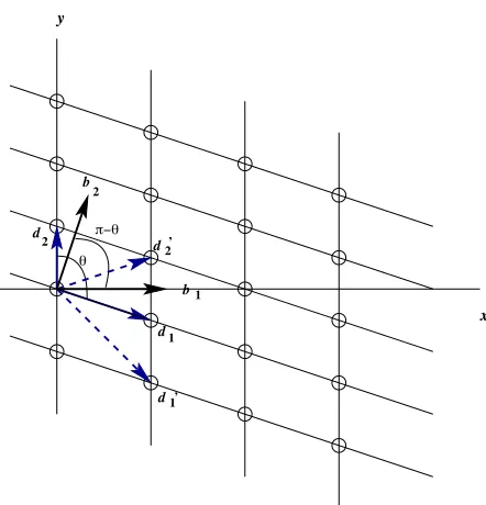
We draw upon the analysis by Brillouin in his classical book Wave Propagation in Periodic Structures (1953) by illustrating a general two-dimensional lattice composed of particles of the same mass, placed at equal distances from one another along two lines intersecting at an arbitrary angle θ in Fig. 2.3. The small circles represent the masses, and distances between the particles in directionsd1 andd2 are not necessarily the same.
The vectors d1 and d2 are basis vectors from the particle designated as the origin of the lattice, and then any point in the array is given by
rl1,l2 =l1d1+l2d2, (2.15)
where li are integers. The basis {d1,d2} is not unique; the pair {d1,d�2} would also
( )
π, π
π, 0
Γ X
M
kx ky
( )
(a) (b)
Figure 2.4: (a) Infinite plate with a doubly periodic array of cylindrical voids. (b) The irreducible Brillouin zone for the doubly periodic square array.
suffice and any linearly independent paird��1 and d��2 would form a valid basis with
d��1 =m1d1+n1d2
d��2 =m2d1+n2d2 �
, m1
m2 � = n1
n2
, (2.16)
where mi, ni are integers. The lattice described by a basis {d1,d2} is known as the
direct lattice.
For any direct lattice, we define a reciprocal lattice with basis vectors b1 and b2 defined by the equation
bi·dk =δik, (2.17)
whereδik is the Kronecker delta andi, k = 1,2.
Brillouin (1953) demonstrates some simple analysis to explain reasons for the term reciprocal lattice. The area of the elementary cell for the direct lattice Sdis given by
Sd=|d1×d2|=|d1||d2|sinθ, (2.18) and similarly for the reciprocal lattice, Sb =|b1||b2|sinθ. The product of these areas
is shown to be unity and therefore the areas Sdand Sb are reciprocals.
The fundamental cell in the direct lattice has the origin at its centre, and is com-monly known as the primitive or Wigner-Seitz cell. In Fig. 2.4(a) we show the array and primitive cell for the particular case of the doubly periodic square array that we discuss in more detail in Section 2.5. The elementary cell is symmetric about the origin and is repeated across the periodic array.
When we move from the direct lattice to the reciprocal lattice, we are effectively considering the Fourier transform. The associated fundamental cell in this reciprocal or Fourier space is called the first Brillouin zone. It is geometrically constructed by drawing the perpendicular bisectors of the reciprocal lattice vectors in the vicinity of the origin. The area enclosed by the intersections of these bisectors is the first Brillouin
Figure 2.5: Converged band diagrams for clamped-edge boundary conditions, for radii (a) a= 0.2 and (b) a= 0.35. Γ,X and M are the vertices of the irreducible part of the Brillouin zone. The inset in (b) shows a magnification of a “collapsed” band. Taken from Poulton et al. (2010).
zone. Within this zone, we may then use symmetry to derive the irreducible Brillouin zone which is the smallest area required to determine the band surfaces of a platonic crystal over the whole of the first Brillouin zone. For the example of the square array, this is a triangular region shown in Fig. 2.4(b). We now introduce some examples of band diagrams for Bloch-Floquet bending waves in a thin elastic plate containing the doubly periodic square array of cylindrical voids.
2.3.2 Dispersion of Bloch waves and band diagrams
The dispersion equation for Bloch waves within the doubly periodic square array of circular voids has been derived by Movchan et al. (2007). We give an outline of this problem in Section 2.5. The dispersion equation solutions are displayed graphically in band diagrams, and Poulton et al. (2010) provided several illustrative examples for various boundary conditions applied to the scatterers.
In Fig. 2.5 (Poultonet al. 2010), we show the band diagram formulated using the standard convention for photonic crystal literature, in that the modulus of the Bloch vectork0 is on the horizontal axis, with the spectral parameter β on the vertical axis, and three principal lines are selected to represent the variation of the Bloch vector
k0= (k0x, k0y). These lines are drawn fromk0 = (0,0) to (π,0), Γ X; fromk0 = (π,0) to (π, π), XM; and from k0 = (0,0) to (−π,−π) with k0x = k0y, M Γ. These three
regions of interest for the variation ofk0 = (k0x, k0y) arise from the irreducible Brillouin
zone (Fig. 2.4(b)).
The band diagrams indicate several modes, or band orders, and the two most notable features of Fig. 2.5(a) for radiusa= 0.2 are the total band gaps above and below the fundamental (zero order) mode, and the lack of a band gap between the second and
Figure 2.6: Converged band diagrams for free-edge boundary conditions, with Pois-son ratioν = 0.3, for radii (a)a= 0.2 and (b)a= 0.35. The bands lie close to those for the Bloch modes of a homogeneous structure. Taken from Poulton et al. (2010).
third modes. For radius a = 0.35 in Fig. 2.5(b), there is a band gap between every band shown, and upon closer inspection, there is the interesting feature that increased radius leads to the second and third bands “collapsing” upon one another, forming a quasi-degenerate pair, shown in the inset.
One further observation made by Poulton et al. (2010) is the tendency of the bands to become very flat as the radius of the voids increase. This is clearly illustrated in Fig. 2.5(b) and these flat bands correspond to trapped modes and slow waves, a very important feature of our analysis throughout this thesis. In Fig. 2.6 (taken from Poultonet al. 2010), we show dispersion curves for the free-edge boundary condition for the same radii. Comparing the two types of boundary condition, flat bands are more likely to arise from clamped-edge conditions, and dispersion curves closer to freely-propagating waves are more likely to arise from the free-edge conditions.
2.4
Concepts from classical optics
The periodic gratings are composed of circular voids separated by a fixed distance d, and are used as the fundamental building block of the platonic periodic arrays. An incident flexural wave is scattered by the grating, producing a set of reflected and transmitted waves. This behaviour is analogous to that of a diffraction grating in a photonic crystal.
2.4.1 Diffraction grating
In optics, a diffraction grating is a periodic structure that splits and diffracts light into multiple beams propagating in different directions, at different wavelengths. The grating acts as a dispersive element. The directions of the beams depend on the spacing
(period) of the grating, the wavelength (or frequency) and each beam is characterized by its specular order m. The relationship between these factors is determined using the Fraunhofer grating equation, which has an equivalent expression for the platonic grating, with a separate case for each of Helmholtz and modified Helmholtz type waves. For general practical applications, the photonic gratings have ridges or rulings on their surface, and are either reflective (analogous to a mirror) or transmissive (analogous to a lens). The grating’s zero-order mode (i.e. specular order m = 0) affords no diffraction and the incident wave behaves according to Snell’s laws of reflection and refraction. For an arbitrary angle of incidence θi (defined as in Fig. 2.1), the grating
equation for a diffraction grating of perioddis
sinθm = sinθi+
mλ
d , (2.19)
whereλis the wavelength of the beam of light of specular orderm. From this equation we obtain the explicit expression for θm:
θm = arcsin
� mλ
d + sinθi �
. (2.20)
The nonzero integers m may be positive or negative, giving diffracted orders on both sides of the zero order beam.
For the platonic grating, the equivalent Fraunhofer equation describing the rela-tionship between the order of the flexural waves p, the angle of incidence θi and the
spectral parameter β is
αp = α0+ 2πp
d , (2.21)
where
α0 =βsinθi and αp =βsinθp=α0+ 2πp
d . (2.22)
To solve uniquely the Helmholtz and modified Helmholtz equations (2.5), a radia-tion condiradia-tion must be imposed to guarantee that only outgoing waves are present at infinity. This is the Sommerfeld radiation condition, named after Arnold Sommerfeld who observed that the energy radiated from the sources must scatter to infinity, and that no energy may be incoming from infinity (Sommerfeld, 1949). The Sommerfeld radiation condition ensures that the complex exponentials in the plane wave expansions in Section 2.2 decay exponentially, rather than grow, and contribute evanescent waves. We define ΩH to represent the set of propagating orders of Helmholtz type. The
setsΩe
H andΩMe contain evanescent waves, of Helmholtz and modified Helmholtz type
respectively. The set ΩMe comprises all integers p since all modified Helmholtz waves that satisfy the Sommerfeld radiation condition are evanescent. Propagating orders are commonly projected onto the normal Oy axis, whilst evanescent waves decay ex-ponentially and travel in the direction parallel to the Ox axis. For any propagating incident wave, of Helmholtz type, which is characterised by its angle of incidence θi,