THE DEVELOPMENT OF TRANSMITTER AND
RECEIVER FOR REMOTE CONTROL HELICOPTER
LIM FANG PANG
B051310013
THE DEVELOPMENT OF TRANSMITTER AND RECEIVER FOR
REMOTE CONTROL HELICOPTER
This report is submitted in accordance with requirement of the University Teknikal Malaysia Melaka (UTeM) for Bachelor Degree of Manufacturing Engineering
(Robotics & Automation) (Hons.)
by
LIM FANG PANG B051310013 920327-01-6357
Disahkan oleh:
_____________________________ ______________________________ Alamat Tetap: Cop Rasmi:
_____________________________ _____________________________ _____________________________
Tarikh: _______________________ Tarikh: _______________________
*Jika Laporan PSM ini SULIT atau TERHAD, sila lampirkan surat daripada pihak berkuasa/organisasi berkenaan dengan menyatakan sekali sebab dan tempoh laporan PSM ini perlu dikelaskan sebagai SULIT atau TERHAD.
BORANG PENGESAHAN STATUS LAPORAN PROJEK SARJANA MUDA
Tajuk: THE DEVELOPMENT OF TRANSMITTER AND RECEIVER FOR REMOTE CONTROL HELICOPTER
Sesi Pengajian: 2016/2017 Semester 2
Saya LIM FANG PANG (920327-01-6357)
mengaku membenarkan Laporan Projek Sarjana Muda (PSM) ini disimpan di Perpustakaan Universiti Teknikal Malaysia Melaka (UTeM) dengan syarat-syarat kegunaan seperti berikut:
1. Laporan PSM adalah hak milik Universiti Teknikal Malaysia Melaka dan penulis. 2. Perpustakaan Universiti Teknikal Malaysia Melaka dibenarkan membuat salinan
untuk tujuan pengajian sahaja dengan izin penulis.
3. Perpustakaan dibenarkan membuat salinan laporan PSM ini sebagai bahan pertukaran antara institusi pengajian tinggi.
4. *Sila tandakan (√)
(Mengandungi maklumat yang berdarjah keselamatan atau kepentingan Malaysiasebagaimana yang termaktub dalam AKTA RAHSIA RASMI 1972)
(Mengandungi maklumat TERHAD yang telah ditentukan oleh organisasi/ badan di mana penyelidikan dijalankan)
SULIT
TERHAD
DECLARATION
I hereby, declared this report entitled ―The Development of Transmitter and Receiver for Remote Control Helicopter‖ is the results of my own research except as cited in reference.
Signature : ………
APPROVAL
This report is submitted to the Faculty of Manufacturing Engineering of Universiti Teknikal Malaysia Melaka as a partial fulfilment of the requirements for the degree of
Bachelor of Manufacturing Engineering (Robotics & Automation) (Hons.). The member of the supervisory is as follow:
i
ABSTRAK
ii
ABSTRACT
iii
DEDICATION
iv
ACKNOWLEDGEMENT
v
TABLE OF CONTENTS
Abstrak I
Abstract ii
Dedication iii
Acknowledgement iv
Table of Contents v
List of Tables viii
List of Figures ix
List of Abbreviations xi
List of Symbols xiii
CHAPTER 1: INTRODUCTION
1.1 Background of the Study 1
1.2 Problem Statement 2
1.3 Objectives 3
1.4 Scopes 3
1.5 Summary 3
CHAPTER 2: LITERATURE REVIEW
2.1 Fundamental of Wireless Communication 4
2.2 Radio Waves Propagation 6
2.3 Type of Wireless Transmission 7
2.3.1 RF Module Transmission 7
2.3.2 IR Wireless Transmission 8
vi CHAPTER 3: METHODOLOGY
3.1 Introduction 17
3.2 General Flowchart of Project Methodology 17
3.3 Literature Review 18
3.4 Planning 20
3.4.1 Hardware Requirement 21
3.4.1.1 Arduino Uno Microcontroller 21
3.4.1.2 RF Transceiver 22
3.4.1.3 Joystick 24
3.4.1.4 Breadboard 26
3.4.1.5 Push Button Switch 27
3.4.1.6 Capacitor 28
3.4.1.7 LED 28
3.4.1.8 Resistor 29
3.4.1.9 Jumper Wires 30
3.4.1.10 Servo Motor 31
3.4.1.11 Battery 31
3.4.1.12 Battery Holder 32
3.4.2 Software Requirement 33
3.4.2.1 Arduino Software (IDE) 33
3.5 Bill of Materials 34
3.6 Development 36
3.6.1 Circuit Development 38
3.6.1.1 Transmitter Circuit 38
3.6.1.2 Receiver Circuit 40
3.6.2 Program Development 42
3.6.2.1 Programming for Transmitter Part 42 3.6.2.2 Programming for Receiver Part 45
3.7 Testing and Analysis 48
3.7.1 Servo Motors Setup Test 49
3.7.2 Data Transmission Range Validation 50
vii CHAPTER 4: RESULT AND DISCUSSION
4.1 Servo Motors Setup Test 51
4.1.1 Results Obtained for Homemade Transmitter and Receiver 51 4.1.2 Results Obtained for Existing Transmitter and Receiver 52 4.2 Data Transmission Range Validation 54 4.2.1 Results Obtained for Homemade Transmitter and Receiver 54 4.2.2 Results Obtained for Existing Transmitter and Receiver 58
4.3 Discussion 60
4.4 Comparison between the Homemade and the Existing Transmitter 61 and Receiver
4.5 Summary 62
CHAPTER 5: CONCLUSION AND RECOMMENDATIONS
5.1 Conclusion 63
5.2 Recommendations 64
5.3 Sustainability 65
5.4 Life-Long Learning 65
REFERENCES 66
APPENDICES
Appendix A Project Gantt Chart for FYP 1 & 2 70
Appendix B Gap Analysis 71
viii
LIST OF TABLES
3.1 The list of the components needed and their prices 34
4.1 The servo motors setup test for each of the channel controlled by the 52 homemade transmitter
4.2 The servo motors setup test for each of the channel controlled by the 53 existing transmitter
4.3 The range validation results obtained for the homemade transmitter 54 and receiver
4.4 The range validation results obtained for the existing transmitter and 59 receiver
ix
LIST OF FIGURES
1.1 The fundamental of radio waves transmission 2
2.1 The distance coverage for frequency ranges 5 2.2 Remote control system block diagram for the aircraft model 8 2.3 The indoor system concept for wireless infrared communication 9 2.4 Non-directional infrared radiation for wireless indoor access to 10
local-area networks
2.5 The family of IEEE802.11 standard 12 2.6 The block diagram for the proposed receiver 15
3.1 The general flowchart of project methodology 18 3.2 The steps for literature review flowchart 19 3.3 The flowchart in project planning process 20
3.4 Arduino Uno microcontroller 22
3.5 NRF24L01 transceiver module 23
3.6 The pin description for NRF24L01 transceiver module 24
3.7 Dual-axis XY joystick module 25
3.8 The pin description for dual-axis XY joystick module 26 3.9 Half size 400 tie-points solderless breadboard 27 3.10 Momentary ON/OFF push button switch 27 3.11 10μF capacitor with voltage rating of 16V 28
3.12 5mm red LED 29
3.13 470Ω resistor 29
3.14 Male-to-male jumper wires 30
3.15 Male-to-female jumper wires 30
x
3.18 9V battery holder 32
3.19 The flowchart of the project development process 36 3.20 The developed transmitter circuit by using Fritzing software 39 3.21 The developed receiver circuit by using Fritzing software 41 3.22 The first part of the programming for transmitter 42 3.23 The second part of the programming for transmitter 43 3.24 The working flows for the programming on the transmitter part 44 3.25 The first part of the programming for receiver 45 3.26 The second part of the programming for receiver 46 3.27 The working flows for the programming on the receiver part 47 3.28 The flowchart for the testing and analysis process 48
xi
LIST OF ABBREVIATIONS
AC - Alternative Current
BS - Base Station
CCW - Counter Clockwise
CMOS - Complementary Metal Oxide Semiconductor
CW - Clockwise
DC - Direct Current
DSSS - Direct-Sequence Spread-Spectrum ELF - Extremely Low Frequency
FCC - Federal Communications Commission FHSS - Frequency Hopping Spread Spectrum FYP - Final Year Project
GND - Ground
ICSP - In-Circuit Serial Programming
IDE - Integrated Development Environment
IEEE - Institute of Electrical and Electronics Engineers IF - Intermediate Frequency
IR - Infrared Radiation
ISM - Industrial, Scientific, and Medical LED - Light Emitting Diode
LOS - Line-of-Sight
MAS - Multiple Address System
MAX - Maximum
MIN - Minimum
MS - Mobile Station
PWM - Pulse Width Modulation
RC - Remote Control
xii
Rx - Receiver
SPI - Serial Peripheral Interface SPST - Single Pole Single Throw
TV - Television
Tx - Transmitter
UGV - Unmanned Guided Vehicle U.S. - United States
xiii
LIST OF SYMBOLS
Hz - Hertz
kHz - Kilohertz MHz - Megahertz GHz - Gigahertz
Kbps - Kilobits Per Second Mbps - Megabits Per Second
m - Meter
mm - Millimeter mA - Milliampere mAh - Milliampere Hour mW - Milliwatt
μF - Microfarad
dB - Decibel
dBm - Decibel Milliwatts
V - Volts
Ω - Ohms
I - Current
1
CHAPTER 1
INTRODUCTION
This chapter presents the background, problem statement, objectives, and scopes of the project.
1.1 Background of the Study
The remote control helicopter requires some devices use to control their movement and direction. In this case, the radio frequency transmitter and receiver are selected as the wireless communication devices use to send and receive the commands given by the humans. Thus, for the whole wireless communication devices, it contains two main parts which are the transmitter part and also the receiver part.
For the transmitter part, the device that will be included is a radio frequency transmitter. It is a device used to transmit the data through wirelessly, and it will be installed inside the remote controller. In order to transmit the data to the environment, the first thing to do is to switch on the remote controller. Then, the joystick needs to be moved so that the microcontroller will be able to read the analog input values from the joystick. Once the input from the joystick is received by the microcontroller, it will start to write the analog output values for radio. When there is a radio available, the electricity will start flowing into the antenna and it will make the electrons to vibrate so that the radio waves will be produced. Thus, the radio will begin to transmit the radio waves to the environment.
2
is available, the receiver will start to receive the radio waves in which it will make the electrons to vibrate in the antenna so that the electric current will be produced. Thus, the analog input values from the radio will be received by the microcontroller, and then it will start to write the analog output values to control the movement and direction of the remote control helicopter.
[image:20.595.88.523.308.454.2]From the above explanation, it is stated that the study of the wireless communication is very important for the remote control devices. The basic components such as the radio frequency transmitter and receiver are needed so that the remote control helicopter will be able to perform based on the desired motion. Figure 1.1 below shows the fundamental of radio waves transmission.
Figure 1.1: The fundamental of radio waves transmission (Source: http://cdn4.explainthatstuff.com/transmitterandreceiver.png).
1.2 Problem Statement
It is not too difficult to make some devices that can send or receive the wireless data. In this 21th century, the wireless technologies have been widely used in order to
3
humans. Therefore, the radio frequency transmitter and receiver are the main devices needed in which it will be able to overcome the problems to monitor a remote control helicopter wirelessly.
1.3 Objectives
1. To develop the radio frequency transmitter and receiver for the nitro remote control helicopter.
2. To install the radio frequency transmitter and receiver on the remote controller and the body of the helicopter, respectively.
3. To validate the range of data transmission by using the homemade and the existing radio frequency transmitter and receiver.
1.4 Scopes
The radio frequency transmitter and receiver are developed to control a nitro remote control helicopter with the brand name of ‗KYOSHO‘. The control parts are limited for only 4 to 6 channels and the range of data transmission is limited for only 100 meters.
1.5 Summary
4
CHAPTER 2
LITERATURE REVIEW
This chapter presents the previous studies or researches done by the other people so that it will help to get some related information or data to apply in this project.
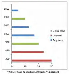
2.1 Fundamental of Wireless Communication
5
Figure 2.1: The distance coverage for frequency ranges (King, 2014).
According to Saputra and Mirdanies (2015), the wireless communication is a technology used to control the multiple patterns of movement on the Unmanned Guided Vehicle (UGV). Normally, the frequency that is used to work on the remote control device is about 2.4GHz. In the wireless system, the remote controller is used to direct the moving path of the omni-directional mobile robot. In order to drive a DC motor to move in clockwise or counter clockwise directions, the received six channel data from receiver module is converted by using the microcontroller into the 4 bits data.
6
2.2 Radio Waves Propagation
According to Modi (2014), the radio waves propagation can be related with the phenomena in which it is happen in the medium between both transmitting antenna and receiving antenna. During the wireless signal transmission, the radio waves that radiated from the transmitter antenna are propagated into the environment in all directions. The amplitude of the radio waves will be decreased as the distance between both transmitter and receiver antennas are increased. The frequency of transmission that within the range of 3kHz to 300GHz is considered as a radio frequency because it is commonly used in the radio communication. The radio frequency spectrum can be divided into different frequency bands based on their particular range of frequency and wavelength. The fundamentals that allow the radio waves to work and spread through the environment are the same since 100 years ago.
Bowditch (2002) stated that a radio wave can be considered as a carrier wave in which it transferred the signal information from the transmitter part to the receiver part. Each radio wave has a particular frequency or band of frequencies which belongs to it. A mobile phone will not be able to work if the area without a radio tower. In order to connect the calling, the small amounts of radio waves that are emitted from the mobile phone will be sent to the radio tower. Then, these towers can only transfer the radio waves to a certain distance and they need to connect with each other so that the calling from one phone will be received by the other phone through the radio waves transmission. The radio waves also can be applied in the leisure activities such as radio controlled cars, helicopters, and airplanes. The radio waves work exactly in the same way because it propagation occurs in the medium between both transmitting antenna and receiving antenna. However, the low quality radio controlled vehicles will have the same frequency or band of frequencies so that they might be controlled by the other controller due to the interference.