Magnetic Field Generation in Plasma Waves Driven
by Copropagating Intense Twisted Lasers
Y. Shi(时银),1,* J. Vieira,2 R. M. G. M. Trines,3 R. Bingham,3,4 B. F. Shen(沈百飞),5,6 and R. J. Kingham1 1
Blackett Laboratory, Imperial College London, London SW7 2AZ, United Kingdom 2GoLP/Instituto Superior T´ecnico, Universidade de Lisboa, Lisbon 1049-001, Portugal 3
Central Laser Facility, STFC Rutherford Appleton Laboratory, Didcot OX11 0QX, United Kingdom 4Department of Physics, University of Strathclyde, Strathclyde G4 0NG, United Kingdom 5
State Key Laboratory of High Field Laser Physics, Shanghai Institute of Optics and Fine Mechanics, Chinese Academy of Sciences, Shanghai 201800, China
6
Department of Physics, Shanghai Normal University, Shanghai 200234, China
(Received 23 February 2018; published 5 October 2018)
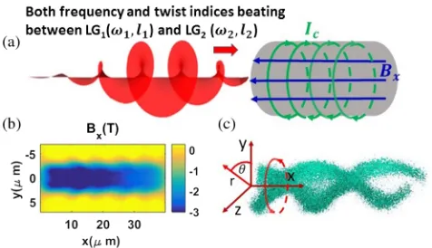
We present a new magnetic field generation mechanism in underdense plasmas driven by the beating of two, copropagating, Laguerre-Gaussian orbital angular momentum laser pulses with different frequencies and also different twist indices. The resulting twisted ponderomotive force drives up an electron plasma wave with a helical rotating structure. To second order, there is a nonlinear rotating current leading to the onset of an intense, static axial magnetic field, which persists over a long time in the plasma (ps scale) after the laser pulses have passed by. The results are confirmed in three-dimensional particle-in-cell simulations and also theoretical analysis. For the case of 300 fs duration,3.8×1017W=cm2peak laser intensity we observe magnetic field of up to 0.4 MG. This new method of magnetic field creation may find applications in charged beam collimation and microscale pinch.
DOI:10.1103/PhysRevLett.121.145002
Since the invention of high power lasers in the 1970s, laser created plasmas have been widely studied and developed into a broad range of applications, ranging from particle accel-erators[1]and x-ray sources to inertial confinement fusion. Most of these studies and applications rely on energy and linear momentum coupling from laser to plasma. Magnetic field creation plays an important role in laser plasma interaction. The most well-known methods of laser-driven dc magnetic field generation in underdense plasma are the inverse Faraday (IF) effect for circularly polarized light[2–5] and generation in wakefields by nonlinear effects[6,7]. For laser irradiated solid density targets, other mechanisms exist such as ponderomotive generation of giga-gauss strength surface magnetic field[8–10]and mega-gauss strength fields in the bulk due to propagation of relativistic electron beams [11,12]. These self-generated fields are beneficial to appli-cations such as charged beam collimation and microscale pinch[4–7,13,14].
However, light can also possess orbital angular momen-tum (OAM) [15]and thereby have the potential to create plasmas with OAM. Every photon in a circularly polarized light beam has a spin angular momentum ofℏ. Conversely, coherent light with a helical wave front possesses OAM that is distinct from spin angular momentum. Helical wave fronts can be represented in a basis set of orthogonal Laguerre-Gaussian (LG) modes and a photon in a LG mode with a twist index oflhaslℏof OAM. While generation and application of such twisted light (e.g., light tweezers[16]) is
well established in conventional optics at low intensities, it has only recently started to be explored at high intensities (I >1016 W=cm2), where the optical medium is necessarily plasma. There have been some recent studies of interactions between intense LG mode laser beams and plasma. Various new simulation phenomena and theories have been proposed [17–23]. Viera et al. have shown that plasmas can obtain OAM as a result of OAM conversion in laser interactions with underdense plasmas[18]. Shiet al.have demonstrated that plasma can acquire high OAM density in a scheme to create relativistic intensity LG modes by reflection of a laser pulse from a foil with a fan structure, using simulations and theory [17]. Mendonca et al. predict a kind of twisted longitudinal electron plasma wave that carries OAM[24]. Their method is based on finding a solution of the electro-static paraxial equation in terms of orthogonal LG functions. Recently, experiments have reported generation of intense OAM light reaching an intensity of1019 W=cm2 [25]and
“plasma holograms”, a forked diffraction grating written onto ablating plasma by laser prepulse with OAM[26].
higher order corrections responsible forB-field generation. An outline of the mechanism is as follows. The beating OAM lasers exert a ponderomotive force with a twisted profile on the electrons. After the laser pulses have passed by, electrons are left oscillating on elliptical orbits in the transverse plane with an azimuthally dependent phase offset. This collectively yields a persistent, rotating wave structure. Associated with this is a nonlinear electrical current, essentially in the configuration of a solenoid that creates a magnetic field.
This mechanism bears some similarity to quasistatic magnetic field generation in laser-driven plasma waves by nonlinear currents [6,7] but, importantly, involves OAM. Studies of inverse Faraday (IF) magnetic field creation have concentrated on the use of circular polarized laser beams with a Gaussian mode (e.g., Refs. [3–5]) though there is some limited amount of theoretical work on linearly polarized beams with a LG mode [2]. The effectiveness of IF depends strongly on the laser absorption coefficient (into the plasma) which is usually very low (and arguably not well understood) so that IF usually requires a relatively long time to create strong fields. In our work, the details of theory and the simulation results will demonstrate a differ-ent method of magnetic field creation, outlined above, which can persist a long time (ps scale for the conditions here) after the laser interaction ceases. The longer-term decay of this magnetic field can be followed based on the knowledge of plasma wave evolution, in principle. The new magnetic field generation mechanism presented here will benefit the same applications that use IF fields, such as improving the quality of laser-produced electron beams[4]. To obtain the results presented in Fig.1, we performed three-dimensional particle-in cell (PIC) simulations using EPOCH [21] with the following parameters. The
frequencies and twist indices of the two laser beams are ω1¼ω0, ω2¼0.95ω0 and l1¼−1, l2¼ þ1,
respec-tively, so that the frequency difference is the same as the plasma frequency ωp¼0.05ω0. Here ω0 is the
gate along the positivexdirection. Both have a diameter ofw¼5 μm (1=e2 intensity measure), pulse duration of τg ¼160fs and peak amplitude ofEp¼4.8×10¹¹ V=m
(peak vacuum intensity isIp¼3.1×10¹⁶ W=cm2). This intensity corresponds to a peak dimensionless vector potential ofa0¼0.2, wherea0¼eE0=meω0c. The
tem-poral pulse envelope is truncated once the intensity drops by 1=e2. The simulation box is 40×25×25μm in the x×y×z directions, respectively. The simulation mesh size is dx¼dy¼dz¼0.05μm. The total number of macro particles per cell is 4. A schematic of the system and some key simulation results are given in Fig. 1. Of particular note are a static axial magnetic fieldBx in x-y
plane, shown in Fig.1(b), and the double helical electron density distribution ne presented in Fig. 1(c). As time
moves on, the double helical density rotates around the x-axis with angular frequency ωp=2. The scheme works
for other choices of twist indices. In particular, frequency beating between a LG and a Gaussian beam is viable and is likely to by easier to realize experimentally, but leads to a more complex theoretical analysis. Therefore, opposite twist indices are chosen in the following analysis to elucidate the physics and verify the PIC results. We have performed PIC simulations changing box size, laser pulse, laser spot, and boundary conditions. All results show the phenomena in our simulations are robust.
First, we solve the nonrelativistic cold electron-fluid equations with beating, LG EM waves as the driving source. (Gaussian units are used). In linear fluid theory (LFT)[27], the linearized electron fluid momentum, mass continuity, and Poisson’s equations describing a laser-driven electron plasma wave can be written, respectively, as
8 > > < > > :
me∂∂u⃗t¼e∇ϕþ fL
!
∂δne
∂t þn0∇·u⃗ ¼0
∇2ϕ¼4πeδn
e
; ð1Þ
wheren0here is the number density of ions (chargeZ¼1) that are assumed to be immobile and uniformly distributed in space,δneis the difference between the ion and electron densities, u⃗ is the velocity of the electron fluid, ϕ is the
electrostatic potential, and fL
!
is the ponderomotive force of the lasers. A cold electron fluid is assumed. LFT is valid for small responses:feϕ=ðmec2Þ; u=c;δne=n0g≪1.
The electric field Eyðr;θ; x; tÞ of each LG mode is
[image:2.612.55.293.45.182.2]E1;2¼ClE0ðp2ffiffiffir=wÞjljexpð−r2=w2Þcosðω1;2t−k1;2xlθÞ, FIG. 1. (a) Illustration of the scheme to generate plasma waves
with helical rotating structure by two copropagating OAM lasers beating both in frequency and twist index. (b) The axial magnetic fieldBxinx-yplane (atz¼0). (c) The double helical electron
densitynerotating aroundxaxis in three dimensions. The time is
where ωp¼ω1−ω2, kp¼k1−k2, and the subscripts 1
and 2 label each pulse. Here,Clis a normalization constant [15]. Also, r, θ, x denote cylindrical polar coordinates about the x axis, as depicted in Fig. 1(c). The slowly varying envelope of each pulse is contained inE0ðx−vgtÞ
and we assume equal group velocities for each mode. The resulting ponderomotive force from the superposition of the (synchronized) pulses is f!Lðr;θ;x;tÞ¼−½C2l2jlje2E2
0= ðmeω20Þ∇½NðrÞð1þcosΦÞ=2, where Φ¼ωpt−kpxþ2lθ and NðrÞ ¼expð−2r2=w2Þðr=wÞ2jlj. The ponderomotive force f!L has an azimuthal component, in contrast to the case of beating, Gaussian modes (which have l¼0). When the laser pulse duration τ is much larger than the plasma period Tp, the solutions of electron density
δneðr;θ; x; tÞ after the laser interaction can be approxi-mated as
δne=n0¼−0.5ηNðrÞYðrÞsinΦ with
YðrÞ ¼8r2=w2−ðkpwÞ2=2−ð4þ8jljÞ; ð2Þ
where the key, dimensionless parameter is η¼C2l2jlja2
0 ðωpτÞ=ðkpwÞ2. Hereη∝a20τ=w2decides the amplitude of
plasma wave and particle oscillation, and is used as an expansion parameter for a subsequent higher order analy-sis. In the PIC simulation shown in Fig. 1,η∼0.3. NðrÞ and YðrÞ are dimensionless radial shape functions. The electrostatic field components Ex, Er, Eθ and velocity of
the electric fluidux,ur,uθ can also readily be calculated.
They are also linear inηandNðrÞ. The important result that
will be used later to determine the current supporting the magnetic field is
uθðr;θ; x; tÞ ¼uθ1sinΦ; where
uθ1¼0.5ηωpw2NðrÞl=r: ð3Þ
Other formulas are given in the Supplemental Material [28]. For simplicity, Eqs. (2) and(3) have been obtained assuming a flattop pulse with durationτ. For the truncated Gaussian pulse used in the PIC simulation [i.e., IðtÞ ¼0 for jt−tpj≥τg=2, where tp¼τg=2 is the time of peak
intensity],τ¼0.75τg is appropriate. We have verified that the plasma wave growth and B-field generation are not significantly influenced by the abrupt truncation of the temporal profile. A simulation where the Gaussian pulse is truncated 3 times further out (i.e.,3τg=2from the center),
shows a slightly larger Bx, consistent with the increased pulse energy. The length of the twisted plasma wave would reasonably be expected to be on the order of the Rayleigh length, which is longer than our simulation window. So, diffraction of the laser beams is not considered here.
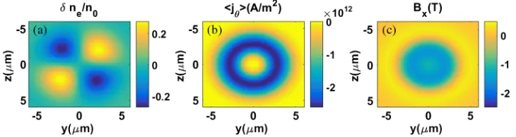
PIC simulation and theory results of electron density δne=n0, time averaged rotating current hjθi and axial magnetic fieldBxare shown in Figs.2and3, respectively,
600 fs after the laser pulse has left the simulation box. The LFT prediction forδne (and also u⃗ and E⃗ which are not shown here) after the laser has passed by agrees well with the PIC simulation results, both qualitatively and quanti-tatively, as seen by comparing Figs.2(a) and3(a). In the LFT the electric current density comes from!je ¼−en
[image:3.612.123.499.48.149.2]0u,⃗
FIG. 2. PIC results of transverse profile of (a) δne, (b) time averaged, azimuthal component of the net current density
hjθi ¼ hje
θþjdisθ i, and (c)Bx, all atx¼20μm and 600 fs after the laser has passed by.
FIG. 3. Linear fluid theory predictions, for the same situation considered in Fig.2. (a)δne, (b) higher order, time-averagedhjθi, and
[image:3.612.125.490.589.686.2]almost 10 A=m [see Fig. 2(b)]. This equates to a normalized current of hjθi=ðen0cÞ∼0.004 and indicates that it is a higher order effect, since a conduction current amplitude of jeθ=ðen0cÞ∼0.07, is expected from LFT. A simple calculation shows that the background electrons need to rotate at a velocity of106 m=s to get such a strong rotating current density, which is rare compared with strong linearly current density. The corresponding angular veloc-ity is5×1011 rad=s, which is 3 orders of magnitude higher than the equivalent angular velocity in the“Light Fan”[17]. The area-averaged axial magnetic field is almost 3 T (i.e., 30 kG) in our simulation.
The result of the LFT is a plasma wave with a helical rotating structure and which carries OAM. It is very different from the longitudinal plasma wave driven by the beating of two Gaussian lasers, where transverse profiles depend only on radius. Additionally, it is not the same as a longitudinal plasma wave with a twisted phase front [24], as proposed by Mendonca et al. There, a solution of the electrostatic paraxial equation in terms of LG functions is given. In our case, Eq.(2), describing the wave’s density perturbation, does not involve use of the paraxial approximation. The primary focus of this Letter is axial magnetic field creation, which according to our PIC simulations are associated with a net rotating current. Since the linear fluid theory predicts zero net azimuthal current, a higher order calculation is required to describe the gen-eration of axial magnetic field by the helical plasma wave. According to Gorbunov’s higher order fluid theory[6,13], the second order (in parameterη) current exists and can be calculated from electron density and velocity in LFT. See the Supplemental Material[28]for more information. With these results we obtain the net current density needed to find the magnetic fieldjθ¼−en1uθ1sin2Φ, wheren1and uθ1are the amplitudes of the first-order electron density and velocity perturbations from LFT. Averaged over time t (i.e., the plasma period) and angleθ(i.e., over2π) we find
hjθi ¼en0clKðCla0Þ4
cτ w
2
4jlj
kpw
; ð4Þ
which scales as hjθi=ðen0cÞ∝η2ðkpwÞ, where K¼
ðjlj þ1=2−ϵÞe−4ϵϵ2jlj−1=2 and ϵ¼ ðr=wÞ2. This
predic-tion forhjθiis shown in Fig.3(b)as rotating currenthjθi, and is close to the simulation result hje
θi þ hjdisθ i in Fig. 2(b). An important point is that this theory links
hjθito the twist indexlof the laser beam drive. In particular
be found in the Supplemental Material[28]. This approxi-mation can always be met by choosing sufficiently low-density plasma or a narrow laser beam. The PIC simulations satisfy these conditions. Given that hjθi rep-resents a solenoidal current which is distributed inr, and ignoring end effects,BxðrÞ ¼ ð4π=cÞRr∞hjθidr0. This theo-retical result forBx, presented in Fig.3(c), compares well with the simulation result shown in Fig.2(c). To obtain a scaling relation between the axial magnetic field and the laser parameters, we use an effective solenoidal current per unit length ofIsol¼
Rr
2
r1hjθidr in the equation for the
B field inside an ideal solenoid, Bsol¼ ð4π=cÞIsol, and choose r1¼0.4w and r2¼0.7w to capture the bulk contribution of the ringlike current density profile. We find that the magnetic field inside the solenoid scales as Bx;½T∼−27τ½2psI2½1016 for the twist indices, plasma density,
and beam radius used in the PIC simulations, whereI2½1016
denotes the peak laser intensity (Ip) in units of1016 W=cm2
and theB-field and pulse duration are in units of Tesla and ps, respectively. More generally, assuming that the distrib-uted solenoid current profile scales with beam radius,
∼whjθipeak, the magnetic field is expected to scale as B∼n10=2τ2I2p=w2.
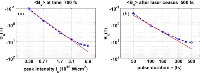
To compare with the simulation, theBxðy; zÞprofile from the PIC calculation, halfway along the structure at x¼ 20μm [see Fig. 1(b)] is averaged within r¼1μm to obtainhBxiPICfor a range of simulations where either pulse
intensity or pulse length is varied from the default con-figuration (used for Fig. 2). Figure 4(a) shows that the theoretical scaling result (when calibrated by a factor of ¾) agrees well with the 3D PIC calculation for peak intensities belowIp¼1.9×10¹⁷ W=cm2, with the PIC result
follow-ing thehBxi∝I2pscaling in this limit. The PIC results also display the predicted hBxi∝τ2 scaling for short pulses
below 200 fs and compare well quantitatively with the calibrated model in this limit. Asτ2I2pgets bigger, the axial magnetic field from the PIC simulations increases more slowly than the value predicted by the theoretical scaling relation and approaches saturation. This discrepancy is likely due to nonlinear effects that become important. For instance,δne=n0 already exceeds 0.2 in the default
The OAM laser-plasma magnetic field generation scheme presented here has benefits over the inverse Faraday mecha-nism, particularly in the subpicosecond duration regime. We have carried out a comparable 3D PIC simulation of IF under identical conditions to those used in Figs. 1 and 2, except that a single circular polarized Gaussian laser with the same power (as the combined beams in our scheme) was used. The axial magnetic field after the laser has passed by is almost 2 orders of magnitude lower than produced by the OAM-beat mechanism in Fig.1(b). This demonstrates that the OAM-beating mechanism reported in this Letter can be more efficient than IF for short laser pulses. Finally, the scheme can also be seen as creation of a laser created θ pinch, on the micrometer and nanosecond scale. Others have reported creation of a nanometer scaleZ pinch from laser irradiated nanowire arrays[14].
In conclusion, a new method of axial magnetic-field generation in underdense plasma, based on intense laser pulses with orbital angular momentum, is proposed. It utilizes two copropagating, subpicosecond duration, laser pulses with different Laguerre-Gauss modes which beat in both frequency and twist index l. This work considers pulses below the relativistic intensity limit. Three-dimensional PIC simulations and supporting theoretical analysis show that the beating OAM laser beams create a twisted ponderomotive force that transfers OAM to the driven electron wave structure. At the same time, Viera et al. have shown that a light spring with a helical spatiotemporal intensity profile can bring OAM and new topological control to laser-plasma accelerators [30]. The plasma wave in our paper has some special characteristics such as a helical, rotating electron density and also a net nonlinear solenoidal current that creates the axial magnetic field. It is different from a 3D longitudinal plasma wave driven by the beat of laser beams with a transverse Gaussian mode. The theory presented here is based on linear fluid equations combined with a higher order fluid theory. It reveals that the 2nd order current exits and also
that the key parameters for this current, and hence the B field, arelandτ2I2p. This establishes that OAM is essential to this magnetic field source. Compared to other laser-based methods of magnetic field creation in underdense plasma such as the inverse Faraday effect, the magnetic field in our scheme can be much stronger and persist a long time, even after the laser interaction stops. Higher magnetic fields should be possible if multiple laser beams are used or higher density plasma is considered. Such a static magnetic field may find some applications to charged beam colli-mation or microscale pinch. Our simulations show that this OAM-laser based magnetic field source is also possible via the beating between a LG and a Gaussian beam, which may be easier for a proof-of-principle experiment.
Dr. Y. S. is a Newton International Fellow. This work is supported by the Royal Society. This work used the ARCHER UK National Supercomputing Service and the Imperial College Research Computing Service. J. V. acknowledges the support of FCT (Portugal) Grant No. SFRH/IF/01635/2015, and B. S. the support from the Ministry of Science and Technology of the People’s Republic of China (Grants No. 2016YFA0401102, No. 2018YFA0404803) and the Strategic Priority Research Program of the Chinese Academy of Sciences (Grant No. XDB16).
*To whom all correspondence should be addressed.
[1] E. Esarey, C. B. Schroeder, and W. P. Leemans,Rev. Mod. Phys.81, 1229 (2009).
[2] S. Ali, J. R. Davies, and J. T. Mendonca,Phys. Rev. Lett. 105, 035001 (2010).
[3] M. G. Haines,Phys. Rev. Lett.87, 135005 (2001). [4] Z. Najmudin, M. Tatarakis, A. Pukhov, E. L. Clark, R. J.
[image:5.612.135.482.48.174.2]Clarke, A. E. Dangor, J. Faure, V. Malka, D. Neely, M. I. K. Santala, and K. Krushelnick,Phys. Rev. Lett. 87, 215004 (2001).
FIG. 4. Comparison of hBxi found in 3D PIC simulations (blue circles connected by dashed lines) with the theory prediction
BxðTÞ∼−20τ2½psI2½1016(red lines) using a logarithmic scale. (a) Varying Ip (laser peak intensity) at fixed pulse duration (τ¼300fs).
(b) Varyingτ(laser pulse duration) at fixed Ip¼3.1×10¹⁶W=cm2and measured promptly after the laser drive has ceased. Here,hBxi
[10] M. Tatarakis, I. Watts, F. N. Beg, E. L. Clark, A. E. Dangor, A. Gopal, M. G. Haines, P. A. Norreys, U. Wagner, M.-S. Wei, M. Zepf, and K. Krushelnick,Nature (London) 415, 280 (2002).
[11] A. P. L. Robinson, D. J. Strozzi, J. R. Davies, L. Gremillet, J. J. Honrubia, T. Johzaki, R. J. Kingham, M. Sherlock, and A. A. Solodov,Nucl. Fusion54, 054003 (2014).
[12] J. R. Davies, A. R. Bell, and M. Tatarakis,Phys. Rev. E59, 6032 (1999).
[13] L. M. Gorbunov, P. Mora, and T. M. Antonsen, Phys. Plasmas4, 4358 (1997).
[14] V. Kaymak, A. Pukhov, V. N. Shlyaptsev, and J. J. Rocca, Phys. Rev. Lett.117, 035004 (2016).
[15] L. Allen, M. W. Beijersbergen, R. J. C. Spreeuw, and J. P. Woerdman,Phys. Rev. A45, 8185 (1992).
[16] A. M. Yao and M. J. Padgett,Adv. Opt. Photonics3, 161 (2011).
[17] Y. Shi, B. Shen, L. Zhang, X. Zhang, W. Wang, and Z. Xu, Phys. Rev. Lett.112, 235001 (2014).
[22] W. Wang, B. Shen, X. Zhang, L. Zhang, Y. Shi, and Z. Xu, Sci. Rep.5, 8274 (2015).
[23] X. Zhang, B. Shen, L. Zhang, J. Xu, X. Wang, W. Wang, L. Yi, and Y. Shi,New J. Phys.16, 123051 (2014).
[24] J. T. Mendonca, S. Ali, and B. Thid´e, Phys. Plasmas 16, 112103 (2009).
[25] A. Denoeud, L. Chopineau, A. Leblanc, and F. Qu´er´e,Phys. Rev. Lett.118, 033902 (2017).
[26] A. Leblanc, A. Denoeud, L. Chopineau, G. Mennerat, P. Martin, and F. Quere,Nat. Phys.13, 440 (2017).
[27] R. Fedele, U. de Angelis, and T. Katsouleas,Phys. Rev. A 33, 4412 (1986).
[28] See Supplemental Material at http://link.aps.org/ supplemental/10.1103/PhysRevLett.121.145002for details on the LFT theory and the higher order fluid theory, which includes Ref. [29].
[29] J. M. Dawson,Phys. Rev. 113, 383 (1959).