R E S E A R C H
Design-for-testing for improved remanufacturability
Katherine M. M. Tant1 &Anthony J. Mulholland1&Andrew Curtis2& Winifred L. Ijomah3
Received: 13 December 2017 / Accepted: 30 August 2018/ #The Author(s) 2018
Abstract
By definition, a remanufactured product must perform to the same (or higher) level as the original product, and must therefore be issued a warranty of the same (or longer) duration. However, many components of remanufactured products will have been subjected to regular stresses in their first cycle of use and may exhibit unseen signs of damage at a microstructural level. This may not affect the remanufactured product’s performance initially but could cause it to fail before its renewed warranty expires. To combat this, we propose that the integrity of individual components is assessed non-destructively before they are consigned to storage. However, lack of remanufacture specific tools and techniques for assessment, particularly non-destructive tools, are major hindrances to this strategy. Furthermore, ease of non-non-destructive testing (NDT) is not currently a consideration in the design of components; components with complex geometries may therefore be difficult to test. This preview paper presents, for the first time, a framework for including NDT suitability as a design criterion at the outset of the component’s lifecycle, where the geometry and surface accessibility of the component are optimised for future assessment. Ensuring that components can be easily inspected would not only allow increased confidence in the structural integrity of remanufactured products, but it would also extend the range of products suitable for remanufacturing. This paper serves as a proof of concept, examining simple inspection scenarios in order to demon-strate how the shape of components and data acquisition geometries can adversely affect the coverage of ultrasonic NDT.
Keywords Design for remanufacture . Non-destructive testing . Ultrasonics . Optimisation . Sensors . Product design
Introduction
The majority of remanufacturing processes described in the literature follow a similar proce-dure: the cores are stripped; components are cleaned, visually assessed, remanufactured and https://doi.org/10.1007/s13243-018-0057-7
* Katherine M. M. Tant [email protected]
stored; then the product is rebuilt and its performance tested [13,16,21]. Due to a shortage of remanufacture-specific tools and expertise for the non-destructive inspection of these compo-nents [11], their integrity is often assessed by their exterior appearance and functional performance. Although it might meet initial performance criteria, interior damage of the structure caused by the strains and stresses experienced in the component’s earlier life-cycles could lead to a shorter lifetime than predicted [14]. Full microstructural assessment at the remanufacturing stage would allow increased confidence in the component’s integrity and would allow remanufacturing processes to be more readily rolled out to components in high stress environments such as those found in the aerospace and energy industries.
Non-destructive testing (NDT) is an umbrella term for a wide range of analysis techniques used to evaluate and characterise components non-invasively [19]. They are employed to detect defects, take thickness measurements and characterise the internal material properties of components. These techniques include liquid penetrant testing, electromagnetic testing, x-ray computed tomography and infrared and thermal testing [19]. Ultrasonic NDT uses high frequency mechanical waves to inspect components, ensuring that they operate reliably without compromising their integrity [22]. It has grown in popularity within the NDT industry in recent years due to the relatively inexpensive and portable equipment required, and its potential for automation and real-time results [2]. There already exists a large and varied literature on the applications of ultrasonic NDT, and the imaging algorithms required to process the collected ultrasonic data are under constant development [8,24].
Although ultrasonic cleaning of remanufacturing cores has been investigated in the past [4,
15], ultrasonic non-destructive testing is not currently applied within the remanufacturing process. However, in [20], it was shown that the overall processing times of complex engine parts and the amount of process scrap was significantly reduced when the level of inspection at theReceive Corestage of remanufacture was increased. Although this study was limited to application of visual and scent inspection, and fibre optic endoscopy of interior surfaces, it provides evidence that further integration of reliable NDT at the initial stage will enhance the overall process efficiency. This is in line with the Poka-yoke system discussed in [23] which is based on the concept that production costs are reduced by ensuring defects are not propagated through the manufacturing process, but are addressed as they occur.
Although there is an increased pay off in extending the inspection protocols for complex components, complex component geometries and composite material microstructures present significant challenges for the successful application of ultrasonic NDT. To combat this difficulty and improve the ease with which NDT can be applied within the remanufacturing process, we propose a framework for including NDT suitability as a consideration in the component’s initial design. By varying the shape and distribution of material within a component, we can maximise the coverage of the ultrasonic field over the structure and minimise the area of dead zones (areas which are not probed by the transmitted wave), thus improving our ability to reliably image internal features of the component.
to be estimated. Our proposed design-for-testing framework is similar only in that the primary objective is to assess the internal wear and tear of components. However, we propose that the ability to implement quantitative NDT on a product will provide a more reliable assessment of a component’s structural integrity than previously proposed design for evaluation strategies.
Optimal structural design is of particular importance to the aerospace, automotive and civil engineering industries [9]. It is typically used to produce economical, lightweight and robust design solutions whilst adhering to size, weight and topological constraints. Often, an optimisation problem requires the minimisation of more than one variable. For exam-ple, companies may often want to look for a structural solution which is both lightweight and low-cost. Thus we have to deal with a multi-objective design optimisation [10]. In this paper, we propose that NDT suitability is introduced as a secondary objective where the subset of solutions shown to be optimal for the existing objectives within a design process are subjected to an optimisation scheme which focusses on maximising the coverage of the ultrasonic field throughout the component whilst minimising the number of ultrasonic transducers required to achieve this (which are also subject to the restrictions on access to its surface). More sophisticated design criteria from the field of experimental design can also be adopted as desired [5, 6]. Design-for-testing has only recently emerged as an important research area [17], whilst design-for-testing for improved remanufacturability has never before been considered. Thus the ideas presented in this paper are cutting edge and the framework developed here will form the basis for future research in the area. As this work is the first of its kind in the area, a novel multi-level optimisation framework, in which both the shape of the component and the location of the ultrasonic transducers are optimised, is proposed. A novel cost function based on the minimum of the pressure field across the component is presented. Inspection scenarios are then simulated for a range of irregularly shaped components as a proof of concept, demonstrating how this cost function depends on the extent of the array aperture and the convexity and surface smoothness of the component. It is hoped that by implementing this approach, not only will the success of in service inspections be enhanced, but the range of products which are suitable for remanufacturing at the end of their first life cycle will be extended.
Methods
Optimisation of the component design
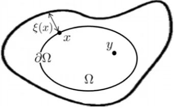
When a component with domainΩ is submitted to ultrasonic NDT, a mechanical force is typically induced at a set of points x on the component’s boundary∂Ω. We consider the coverage of the resulting pressure field throughout the component, which is dependent on the source placement and the component’s geometry and material properties. The pressure measured at a pointy∈Ω, denoted here asz(y,t), can be written
z y;ð Þ ¼t F y;ð t;θ;∂Ω;xÞ ð1Þ
observed over alltat each pointyis plotted. The coverage map is used as a proxy for the ease with which NDT can be applied and is quantified here by
ϕ¼min
y∈ΩM yð Þ ¼miny∈Ω maxt∈Rþjz y;ð Þjt : ð2Þ
Note that alternative measures of the mapMmay be explored; for example the mean value of the pressure field throughout the component, and the number of points in the domainΩwhich lie above some pre-determined threshold relative to the total number of points, are examined in theResultssection of this paper.
By introducing more sources at different locations on the component’s boundary, we can modify the overall coverage of the component as we are effectively illuminating it from an increased range of angles. To incorporate this, we introduce a probability density functionξ(x) which describes the likelihood that a source is placed at pointxon the component boundary (see Fig.1). Taking, for the moment, the material propertiesθto be fixed, we now have all of the ingredients required to define a design criterion function:
Ψ ξð ð Þx ;∂ΩÞ ¼min
y∈Ω maxt∈Rþ ∫∂Ωjz y;ð t;θ;∂Ω;xÞjξð Þx dx: ð3Þ
Here, integrating overxallows us to effectively sum the contributions from all sources, and this is weighted by the probability density functionξ(x) to give an expected value. As before, the maximum value atyover alltis taken (this is effectively mapM) of which the minimum is taken as the coverage measure Ψ(ξ(x),∂Ω). As we are optimising over two parameters: the shape of the component and the placement of sources, the second of which is dependent on the first, we adopt a bi-level optimisation approach. To clarify this approach, we initially isolate the upper level optimisation.
Problem 1: Optimising the component design
We first of all wish to maximiseΨ(ξ(x),∂Ω) by finding the optimal admissible boundary design
∂Ω∗given by
∂Ω*¼arg max
∂Ω∈D Ψ ξð ð Þx;∂ΩÞ; ð4Þ
whereDis the set of admissible component boundary geometries (subject to the initial design constraints set by the product manufacturer). For this upper level optimisation, we study the full aperture immersion testing scenario (see Fig.2a) where the irregularly shaped component is placed in a rectangular water bath and encircled by sources. This allows us to isolate the
[image:4.439.222.393.507.612.2]effects of the component shape on the ultrasonic coverage. We assume here that ξ(x) = 1∀
x∈Γ whereΓis the boundary of the immersion inspection domain. The outcomes of this upper level optimisation will be used to reduce the dimension of the search space and provide constraints for the lower level optimisation of the source placement (which is of course dependent on the boundary of the component).
Problem 2: Calculating optimal source placement
The component geometry ∂Ω will now be constrained by the findings of the upper level optimisation as described in Problem 1. For a given component Ω for which the material propertiesθand boundary∂Ωare known, we wish to find the optimal source placementξ∗(x)
ξ*ð Þ ¼x arg max
ξ∈Φð Þ∂Ω Ψ ξð ð Þx ;∂ΩÞ; ð5Þ
whereΦ(∂Ω) is the set of admissible source distributions for the given component boundary
∂Ω (thus taking into account the restrictions to the component’s surface access). Using a Markov chain Monte Carlo (MCMC) method coupled with Metropolis-Hastings criterion [1], we can iterate over the model space, changing the distribution of sources ξ(x) over the component’s surface to maximiseΨ(ξ(x);∂Ω). Thus we obtain a component geometry which lies within the initial design constraints and, when inspected by ultrasonic transducers placed according toξ∗(x), maximises our ability to successfully test the component non-destructively.
Simulation of the ultrasonic inspection of a given component design
Having set up this design optimisation framework for ultrasonic array NDT, we now demon-strate the effects that the source placementξ(x) and component boundary ∂Ω have on the coverage Ψ. The software package PZFlex [14] was identified as the ideal environment to examine the effects of inspection aperture and component design on the coverage of the induced ultrasonic field. Using this finite element software, we were able to simulate the ultrasonic inspection of irregularly shaped components. We initially work within a two dimensional framework. This is a fair representation of the physical scenario as ultrasonic trandsucers are usually placed in a single plane so that we effectively inspect a slice of the
[image:5.439.76.362.55.196.2]component. However, it can be noted that PZFlex has the capability to read in computer aided design (CAD) files of 3D components [7] and so the framework developed can easily be extended to more complex inspection scenarios in the future if necessary.
In this paper, we study two different inspection scenarios. The first is a four sided inspection, where an array of sources are placed on each side of the two-dimensional square domain, enclosing the component under inspection and providing a full aperture interrogation (see Fig.2a). The second scenario models a linear array of sources placed on a single side of the inspection domain (Fig.2b). This single-sided inspection better represents the scenarios faced by NDT operators in industry where only a sub-region of the surface can be accessed. In both cases, the elements were fired simultaneously to induce plane waves and inject the maximum amount of energy into the system. Note that here the sources are not placed on the component boundary but are instead placed in the water surrounding the component. This is known as immersion testing and allows for testing of irregularly shaped components by standard phased array equipment.
Results
Effects of component design on ultrasonic coverage
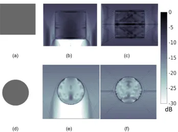
To begin, we examine the simplest case and compare the ultrasonic coverage of a steel disc placed in water against that of a rectangular steel block placed in water (the geometries are shown in Fig.3a and d). Initially, a one sided inspection was simulated where a plane wave was induced at the top of the domain. The wave travels through the water host until it reaches the component where some energy penetrates its surface and, due to the mismatch in impedance between the water and steel, a high proportion of the energy is reflected or redirected around the component. The results are shown in Fig.3b and e for the rectangular block and disc respectively, and both are plotted over a dynamic range of 30 dB. The maps are quantified by the mean, variance, minimum amplitude and percentage of pixels which lie above the -20 dB threshold (see Table1) and it can be concluded that the coverage is better in the rectangular sample. The results arising from a full aperture inspection are shown in images (c) and (f) and again, from the values in Table1, the rectangular component exhibits a higher pressure field throughout. Note in this case however, that if we take the variance of the pressure field as a measure of the uniformity of the coverage, we observe that the disc exhibits a more even coverage than the rectangular block. However, the mean value tells us that the coverage is of lower quality in the disc case. This can be attributed to the fact that its rounded boundaries guide the pressure wave around the object, thus reducing penetration and lessening the component’s coverage.
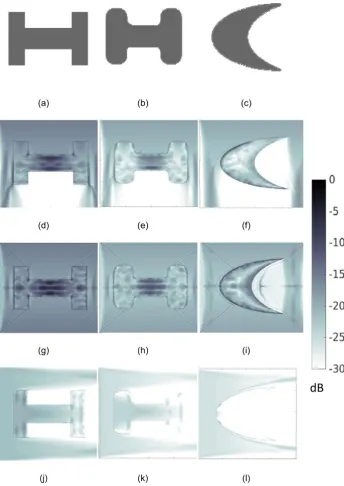
the full aperture case (Fig.4g). When the corners are rounded, as in geometry 4 (b), this effect is lessened. Instead, the amplitudes are highest at the rounded surface of the component as observed previously in the disc case, and the coverage within the component deteriorates (Fig.4e and h). Quantitative measures of the coverage are recorded in Table2
and the values for the limited aperture and full aperture cases can be compared. Note that there is an improvement in coverage in each case when the full aperture is employed however this must be tempered by the fact that four times as much energy is entering the system.
[image:7.439.47.396.46.303.2]The ultrasonic coverage was then altered by placing the sources at the left hand side of the domain. Much of the energy is trapped in the left vertical bar of the component in Fig.4j as the wave is reflected off the inner steel-water interface. The same result is observed in the case shown in Fig.4k, but to a lesser extent due to the curved surface (less energy is transmitted into the component to start with). In both cases, the vertical bar on the right hand side receives very little coverage and would be considered a‘dead zone’.
Table 1 Quantitative measures of the coverage maps plotted in Fig.3
Geometry Inspection Aperture Mean (dB) Var (dB) Min (dB) >−20db (%)
(a) Block Limited −7.6 8 −17.8 100
Full −7 11.5 −13 100
(d) Disc Limited −19 9 −23.5 48
Full −17 9.3 −24 64
(a) (b) (c)
(d) (e) (f)
dB
[image:7.439.53.393.549.614.2](a) (b) (c)
(d) (e) (f)
(g) (h) (i)
(j) (k) (l)
dB
[image:8.439.47.392.50.537.2]Finally, a crescent shaped component was examined (Fig.4c). As observed in all previous examples, the curved surface leads to poor coverage of the component. Naturally, when the concave curved surface is illuminated by the plane wave (as in the full aperture case shown in Fig.4i) a focal point of energy outside of the component is created, which is detrimental to our purpose.
Discussion
It has already been shown that enhanced inspection protocols serve to reduce process waste and improve overall efficiency in the remanufacturing of complex components [20]. Currently, inspection protocols are limited in most cases to visual and scent inspections. Where more advanced inspection techniques such as fibre optic endoscopy are applied, they are still limited to superficial, surface examinations. We propose that ultrasonic inspection is most suited to assessing the structural integrity of a compo-nent’s interior due to its ability to reliably detect sub surface damage, inexpensiveness, automation potential and portability. The ability to reliably detect interior damage and weaknesses will ensure that remanufacturing practices can be extended and applied to expensive components used in heavy industry which are subjected to extreme stresses on a daily basis. In fact, it has previously been reported that the only way to increase the amount of remanufacturing within the aerospace industry would be to invest in the development of more effective NDT strategies to ensure more reliable structural assessments [3].
[image:9.439.47.393.69.152.2]The major challenge in integrating ultrasonic NDT within the remanufacturing process is that its deployment can be inhibited when components exhibit complex geometries or are constructed from heterogeneous media. This is particularly relevant in remanufacturing as components often feature complex geometrical features to facilitate easy disassembly. We have shown using simple examples that a component’s convexity, surface smoothness and inspection aperture have a significant effect on the ultrasonic coverage and the existence of dead zones. By presenting a framework which allows original equipment manufacturers (OEMs) to account for the component’s testability at the design stage, we hope that ultrasonic testing can become better integrated in the remanufacturing process at the Receive Core stage. It is important to note however, that ultrasonic NDT has been presented here as a secondary design constraint and so this approach will be limited by the
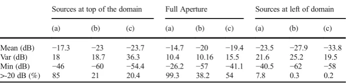
Table 2 Comparing the coverage afforded by three different inspections for geometries (a), (b) and (c) in Fig.4
Sources at top of the domain Full Aperture Sources at left of domain
(a) (b) (c) (a) (b) (c) (a) (b) (c)
Mean (dB) −17.3 −23 −23.7 −14.7 −20 −19.4 −23.5 −27.9 −33.8
Var (dB) 18 18.7 36.3 10.4 10.16 15.5 21.6 25.2 19.5
Min (dB) −46 −60 −54.4 −26.2 −57 −41.1 −40.5 −62 −58
flexibility in the original design of the component; can the design be altered to consider the component’s testability without modifying its functionality or incurring unwarranted costs? However, there are scenarios in which it would be a primary objective, trading off directly with cost and waste reduction; if the integrity of a component is critical to the safety of a product, and without NDT the safety cannot be guaranteed and hence the component cannot be remanufactured, the ability to apply NDT techniques may have a first-order effect on the component’s lifetime value. Additionally, ultrasonic NDT is ineffective in detecting damage in the near field of the array and so the integration of this inspection methodology is complementary to the existing visual inspection protocols which provide an efficient and economical way of detecting surface breaking damage. Future work will focus on developing a software package based on the presented frame-work which quantifies a component’s testability and produces designs with enhanced testability. Studies which weigh the cost benefit of the enhanced process efficiency against the additional cost incurred by implementing of ultrasonic inspection will also follow. Of course, for simply designed components, enhanced inspection will not always be econom-ically viable and so an outstanding challenge will be in determining when this process is worthwhile.
Conclusions
The primary aim of this paper was to present a mathematical framework for including ease of NDT as a design consideration, and to demonstrate that by altering a component’s shape and data acquisition geometry, the coverage of the pressure field can be adjusted. It is hoped that by considering NDT suitability in the design process, not only will the success of in service inspections be enhanced, but the range of products suitable for remanufacturing will be extended.
Acknowledgements This work was funded by the Engineering and Physical Sciences Research Council (grant number EP/P005268/1). The authors would like to thank the team at PZFlex (Glasgow office) for their continued support.
Authors’contributions Each author contributed to the development of the novel concept central to this paper. The simulations were run by KMMT.
Data statementAll results presented in this publication can be reproduced using the model made available at the University of Strathclyde KnowledgeBase athttps://doi.org/10.15129/ed8564a2-ad9f-4ba3-9769-c6a4980af17c
References
1. Aster RC, Borchers B, Thurber CH (2005) Parameter Estimation and Inverse Problems, Elsevier 2. Brown RH, Pierce SG, Collison I et al (2015) Automated full matrix capture for industrial processes. 41st
Annual review of progress in quantitative nondestructive evaluation: volume 34.1650:1967–1976 3. Centre for remanufacturing and reuse: remanufacturing in the UK: a snapshot of the UK remanufacturing
industry (2010)http://www.remanufacturing.org.uk/pdf/story/1p342.pdf[Accessed 08/06/18]
4. Chang Y, Bae JH, Yi HC (2013) Ultrasonic cleaning of used plastic parts for remanufacturing of multifunctional digital copier. Int J Precis Eng Manuf 14(6):951–956
5. Chepuri SP, Leus G (2015) Sparsity-promoting sensor selection for non-linear measurement models. IEEE Trans Signal Process 63(3):684–698
6. Coles D, Prange M, Djikpesse H (2015) Optimal survey design for big data. Geophysics 80(3):11–22 7. Dobson J, Tweedie A, Harvey G et al (2016) Finite element analysis simulations for ultrasonic array NDE
inspections. 42nd Annual review of progress in quantitative nondestructive evaluation: incorporating the 6th European-American workshop on reliability of NDE, vol 1706. Melville
8. Fan C, Caleap M, Pan M, Drinkwater BW (2014) A comparison between ultrasonic array beamforming and super resolution imaging algorithms for non-destructive evaluation. Ultrasonics 54(7):1842–1850 9. Farkas J, Jármai K (1997) Analysis and optimum design of metal structures. CRC Press 10. Farkas J, Jármai K (2008) Design and optimization of metal structures. Elsevier
11. Hammond R, Amezquita T, Bras B (1998) Issues in the automotive parts remanufacturing industry: a discussion of results from surveys performed among remanufacturers. Eng Des Autom 4:27–46 12. Hatcher GD, Ijomah WL, Windmill JFC (2011) Design for remanufacture: a literature review and future
research needs. J Clean Prod 19(17):2004–2014
13. Ijomah WL, McMahon CA, Hammond GP, Newman ST (2007) Development of design for remanufacturing guidelines to support sustainable manufacturing. Robot Comput Integr Manuf 23:712–719 14. Koul AK, Castillo R (1988) Assessment of service induced microstructural damage and its rejuvenation in
turbine blades. Metall Trans A 19(8):2049–2066
15. Liu W, Zhang B, Li MZ, Li Y, Zhang HC (2013) Study on remanufacturing cleaning technology in mechanical equipment remanufacturing process. In Re-engineering manufacturing for sustainability, Springer, Singapore, p 643–648.
16. Lund RT (1984) Remanufacturing: the experience of the U.S.A. and implications for the developing countries. World bank technical paper No. 3
17. Mosch M, Oster R, Grosse CU (2016) Non-destructive testing of CFRP in the design process-a generic approach to describe and optimize non-destructive testing. In 19th WCNDT, Munich, Germany 18. PZFlex (2017) Thornton Tomasetti Defence Ltd 6th Floor South, 39 St Vincent Place, Glasgow, Scotland,
G1 2ER, United Kingdom
19. Raj B, Jayakumar T, Thavasimuthu M (2002) Practical non-destructive testing. Woodhead Publishing 20. Ridley S.J. (2012) Improving the efficiency of the remanufacture of complex mechanical assemblies with
robust inspection of core units. In: Matsumoto M, Umeda Y, Masui K, Fukushige S. (eds) Design for innovative value towards a sustainable society. Springer, Dordrecht, ISBN 978–94–007-3010-6
21. Ridley SJ (2013) Increasing the efficiency of engine remanufacture by Optimising pre-processing inspection –a comprehensive study of 2196 engines at Caterpillar remanufacturing in the UK. PhD Dissertation: The University of Strathclyde
22. Schmerr LW (2016) Fundamentals of ultrasonic nondestructive evaluation. Springer
23. Shingo S (1986) Zero quality control: source inspection and the poka-yoke system. CRC Press
24. Tant KMM, Galetti E, Mulholland AJ, Curtis A, Gachagan A (2018) A Transdimensional Bayesian Approach to Ultrasonic Travel-time Tomography for Non-Destructive Testing. Inverse Problems 34(9): 095002
Affiliations
Katherine M. M. Tant1&Anthony J. Mulholland1&Andrew Curtis2&Winifred L. Ijomah3
Anthony J. Mulholland [email protected]
Andrew Curtis [email protected]
Winifred L. Ijomah [email protected]
1 Department of Mathematics and Statistics, University of Strathclyde, Livingstone Tower, Richmond Street,
Glasgow, UK
2
School of Geosciences, Grant Institute, University of Edinburgh, Kings Buildings, Edinburgh, UK 3