Motorised momentum exchange space tethers: the dynamics of
asymmetrical tethers, and some recent new applications
Matthew Cartmell1,2,*, Olga Ganilova1,2, Eoin Lennon1, and Gavin Shuttleworth1
1Department of Mechanical & Aerospace Engineering, University of Strathclyde, Glasgow, G1 1XJ, Scotland, UK 2Strathclyde Space Institute, University of Strathclyde, Glasgow, G1 1XJ, Scotland, UK
Abstract. This paper reports on a first attempt to model the dynamics of an asymmetrical motorised momentum exchange tether for spacecraft payload propulsion, and it also provides some interesting summary results for two novel applications for motorised momentum exchange tethers. The asymmetrical tether analysis is very important because it represents the problematic scenario when payload mass unbalance intrudes, due to unexpected payload loss or failure to retrieve. Mass symmetry is highly desirable both dynamically and logistically, but it is shown in this paper that there is still realistic potential for mission rescue should an asymmetry condition arise. Conceptual designs for tethered payload release from LEO and lunar tether delivery and retrieval are also presented as options for future development.
1 Introduction
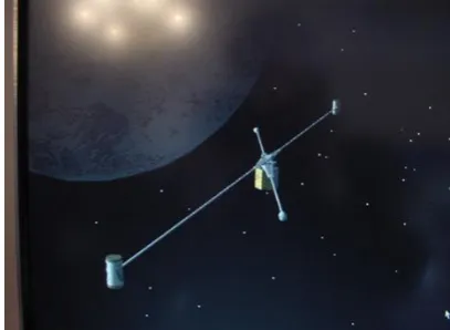
[image:1.595.324.528.379.528.2]Momentum exchange tether dynamics have been extensively studied in recent years, and are of current considerable interest internationally as a technology for cost effective and environmentally clean propulsion of payload mass from Low Earth Orbit (LEO). A conceptual design for a motorised momentum exchange tether is given in Figure 1 where the central facility motor drive shaft attaches to the propulsion sub-spans by mean of a gantry, mounted so that it can be rotated by the shaft. Typical performance figures for an operational motorised MET on a circular LEO predict an orbit velocity in the region of 7.6 km/s and a tether generated increment of around 3.1 km/s, which has the potential to accelerate the outer payload, at an optimal release position, to around 10.7 km/s. This is fast enough for Earth escape, using a tether made of Spectra2000TM. It should be noted that a fundamental requirement for motorised spin is shown in Figure 1 comprising a counter-inertia in the form of an additional pair of tethers and counter-masses attached to the motor stator [1]. This sub-system is required to satisfy Newton’s third law of motion and is not analysed here but is assumed to be present, coupling through the drive motor electrodynamics in order to provide the requisite operational configuration.
Fig. 1. A motorised momentum exchange tether in LEO.
located at both ends, or, conversely, no payloads on either end of the tether) cannot be absolutely guaranteed, a study of the asymmetrical mass distribution problem was seen to be necessary. In this paper an initial model is proposed, with some calculations that suggest that a pragmatic level of reserve chemical propulsion on board each payload could be used to rescue a mission in which asymmetry has arisen for some reason. This is investigated in the form of the complete loss of one of the payloads. This is followed by discussions of two further investigations in which the tethered release of small payloads from an Earth orbiter and the use of a specialised lunavator
tether with an end reeling facility for lunar touchdown are investigated. These two application scenarios in fact reflect different levels of mass symmetry requirement and on that basis they provide interesting platforms for further research into robust solutions to the tether asymmetry problem.
2. Reference model for a planar
motorised tether on an elliptical Low
Earth Orbit
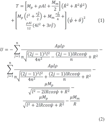
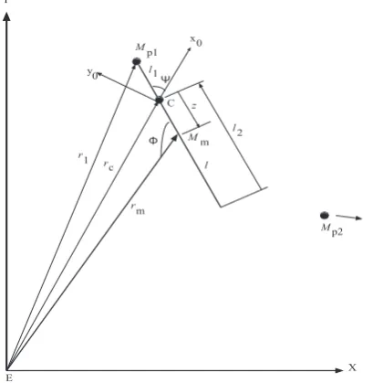
We start with the kinetic and potential energies for a mass-discretised dumb-bell tether (i.e. in symmetrical rigid-body form), and these can be stated as follows [3] for the system shown diagrammatically in Figure 2, with an Earth-fixed frame EXY and a tether-fixed frame Cx0y0. The tether is assumed to be symmetrical
in length and therefore point C, the location of the central facility, is exactly half-way between each payload, Mp. Note that the time argument has been
dropped from R(t), θ(t), and ψ(t) in both equations for clarity and compactness. Quantities are defined in full after the equations.
𝑇𝑇 = [𝑀𝑀𝑝𝑝+ 𝜌𝜌𝜌𝜌𝜌𝜌 +𝑀𝑀2 ] (𝑅𝑅𝑚𝑚 ̇2+ 𝑅𝑅2𝜃𝜃̇2)
+ [𝑀𝑀𝑝𝑝(𝜌𝜌2+
𝑟𝑟𝑝𝑝2 2) + 𝑀𝑀𝑚𝑚
𝑟𝑟𝑚𝑚2
4 +
𝜌𝜌𝜌𝜌𝜌𝜌
12 (4𝜌𝜌2+ 3𝑟𝑟𝑇𝑇2)
] (𝜓𝜓̇ + 𝜃𝜃̇)2 (1)
𝑈𝑈 = − ∑ 𝜌𝜌𝐴𝐴𝜌𝜌𝜌𝜌
𝑛𝑛√(2𝑗𝑗 − 1)4𝑛𝑛2 2𝜌𝜌2− (2𝑗𝑗 − 1)𝜌𝜌𝑅𝑅𝑙𝑙𝑙𝑙𝑙𝑙𝜓𝜓𝑛𝑛 + 𝑅𝑅2
−
𝑛𝑛
𝑗𝑗=1
∑ 𝜌𝜌𝐴𝐴𝜌𝜌𝜌𝜌
𝑛𝑛√(2𝑗𝑗 − 1)4𝑛𝑛22𝜌𝜌2+ (2𝑗𝑗 − 1)𝜌𝜌𝑅𝑅𝑙𝑙𝑙𝑙𝑙𝑙𝜓𝜓𝑛𝑛 + 𝑅𝑅2
−
𝑛𝑛
𝑗𝑗=1
𝐴𝐴𝑀𝑀𝑝𝑝
√𝜌𝜌2− 2𝜌𝜌𝑅𝑅𝑙𝑙𝑙𝑙𝑙𝑙𝜓𝜓 + 𝑅𝑅2−
𝐴𝐴𝑀𝑀𝑝𝑝
√𝜌𝜌2+ 2𝜌𝜌𝑅𝑅𝑙𝑙𝑙𝑙𝑙𝑙𝜓𝜓 + 𝑅𝑅2−
𝐴𝐴𝑀𝑀𝑚𝑚
𝑅𝑅
[image:2.595.312.533.69.287.2](2)
Fig. 2. A planar dumb-bell tether in LEO where E represents the centre of the Earth and EXY is an Earth fixed frame.
Lagrange’s equations are used to obtain three
differential equations of motion based on generalised coordinates R(t), θ(t), and ψ(t). These are intricately coupled, nonlinear, and lengthy, and are not reproduced here but are obtainable in full in [3]. They represent the planar orbital dynamics of the tether, accommodating orbital eccentricity. The data used for the study is as follows. Tether sub-span length l = 50 km, payload masses Mp = 1000 kg, central facility mass
Mm = 5000 kg, tether density ρ = 970 kg/m3,
cross-sectional area A = 62.83*10-6 m2, equal radii of central
facility and payloads rm = rp = 0.5m, standard
gravitational parameter μ = 3.9877848*1014 m3/s2,
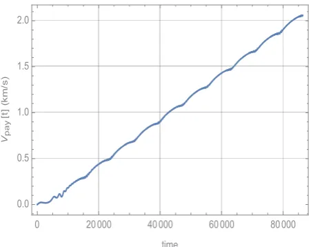
drive torque τ = 5MNm, and integration time = 86400 s. Initial conditions are R(0) = 6870000 m, θ(0) = 97.1877 rad, and ψ(0) = 0 rad, and R’(0) = 0 m/s, θ’(0) = 0.00121485 rad/s, and ψ’(0) = 0 rad/s. These initial conditions accommodate an elliptical LEO (e = 0.20004) on which the tether’s long-term motion is predicted to be in the form of a monotonic spin. The tangential velocity of the payloads relative to the COM at the centre of the system builds up usefully. We note that the centripetal stress is proportional to the angular velocity squared. The system responses in the time domain are given in the following Figures. Figure 3 shows a continuous build-up in the angular position of the tether over time, with Figures 4 and 5 indicating the increasing angular velocity and the tangential velocity of the tip of each sub-span relative to the spin axis located at the CoM of the tether. The increase in centripetal stress in the tether over time is shown in Figure 6 where it can be seen that this is still within reasonable limits for Spectra2000TM at the end of the
integration time of 24 hours. The orbital elements are given in Figures 7-10 with clear indication of perigee and apogee locations for R in Figure 7, and a commensurate ripple in θ shown in Figure 9.
⚫
⚫ l
l Mp
Mp C, Mm
x0
y0 ψ
R(t Y
X E
[image:2.595.60.281.509.768.2]Fig. 3. Angular displacement of the tether with time.
Fig. 4. Angular rate of the tether with time.
[image:3.595.57.284.268.448.2]Fig. 5. Tangential velocity of the sub-spans relative to the spin axis with time.
Fig. 6. Sub-span centripetal stress with time.
Fig. 7. Magnitude of position vector R with time.
Fig. 8. Time rate of change of magnitude of R.
0 20000 40000 60000 80000
0 500 1000 1500
time
ψ
[t
]
(r
ad
)
0 20000 40000 60000 80000
0.00 0.01 0.02 0.03 0.04
time
ψ
'[t
]
(r
a
d/
s)
0 20000 40000 60000 80000
0.0 0.5 1.0 1.5 2.0
time Vp
a
y
[t
]
(k
m
/s
)
0 20000 40000 60000 80000
0.0 0.2 0.4 0.6 0.8 1.0 1.2 1.4
time σce
nt
[t
]
(G
P
a)
0 20000 40000 60000 80000
7000 7500 8000 8500 9000 9500 10000 10500
time
R
[t
]
(k
m
)
0 20000 40000 60000 80000
- 1.5 - 1.0 - 0.5 0.0 0.5 1.0 1.5
time
R
'[t
]
(k
m
/s
[image:3.595.317.543.271.452.2] [image:3.595.315.541.479.668.2] [image:3.595.57.283.490.669.2]Fig. 9. True anomaly with time.
Fig. 10. Rate of change of true anomaly with time.
This model shows some interesting and typical tether phenomena on orbit and was useful for an initial data scoping study for the more complex scenario of the asymmetry case in the next section.
3. Conditions for Mass Asymmetry
It was shown by [8, Fu] that even small mass asymmetry will quickly lead to catastrophic failure of the tether as the propulsion side proceeds to collide with the outrigger counter-inertia system. A typical motorised MET system is shown in side-elevation in Figure 11.
Fig. 11. Side elevation of the tether showing the propulsion and outrigger tethers and the separation distance H between them.
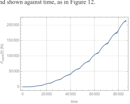
The separation distance H is assumed to comprise the height of the motor drive system. The centripetal load in a sub-span due to the mass of a payload and the tether sub-span can readily be calculated from,
𝐹𝐹𝑐𝑐𝑐𝑐𝑐𝑐𝑐𝑐 = (𝑀𝑀𝑝𝑝𝑙𝑙 +𝜌𝜌𝜌𝜌𝑙𝑙 2
2 ) 𝜓𝜓̇2 (3)
[image:4.595.321.533.170.339.2]and shown against time, as in Figure 12.
Fig. 12. Sub-span centripetal load as a function of time.
4. Asymmetry model
Under normal operating conditions the two sub-spans each develop equal centripetal loads, and although the moment arms, about the half-way point, of H/2 mean that there are moments associated with the centripetal loads in each sub-span these are equal and opposite and therefore mutually balancing. These loads can reach 200kN for typical design data, and would normally be balanced by each identical sub-span. But in the asymmetrical configuration the tether will obviously be de-stabilised so that it is pushed out of the spin-and-orbit plane. The precise effect depends on the physical design adopted but it cannot be ignored. For the moment arm of H/2, where H could be up to 3 m, the corresponding moment could reach up to 300 kNm. A corrective counter-moment, but exerted instead over a moment arm comprising the full length of the sub-span, (taken to be 50 km in this example) would typically require a normal thrust of up to 6N and this could easily be obtained from simple cold-gas thrusters, and provided as emergency propulsion in each payload. So, although the out of balance moment generated by asymmetry could probably be inexpensively corrected using low thrust propulsion on board the payloads there will also be the problem of whole-body translation of the tether to consider, due to subsequent re-positioning of the CoM. It is this that provides the focus of the remaining analysis, with an asymmetry scenario shown in Figure 13.
0 20000 40000 60000 80000
100 110 120 130 140 150 160
time
θ
[t
]
(r
ad
)
0 20000 40000 60000 80000
0.0006 0.0007 0.0008 0.0009 0.0010 0.0011 0.0012
time
θ
'[
t]
(r
a
d
/s
)
0 20000 40000 60000 80000 0
50000 100000 150000 200000
time
Fce
nt
[t]
(N
Fig. 13. Asymmetrical tether in the Earth-fixed frame with asymmetry due to the unplanned loss of payload Mp2.
The CoM is now no longer co-located with the central facility and moves closer to the remaining payload. This means that the tether will translate through z(t) to stay on orbit. We can relate the position vector magnitudes through simple geometry to get,
𝑟𝑟𝑚𝑚(−2𝑙𝑙𝑟𝑟𝑐𝑐𝑧𝑧𝑧𝑧𝑧𝑧𝑧𝑧𝑧𝑧 + 𝑙𝑙𝑟𝑟𝑐𝑐2+ 2𝑟𝑟𝑐𝑐𝑧𝑧2𝑧𝑧𝑧𝑧𝑧𝑧𝑧𝑧 − 𝑟𝑟𝑐𝑐2𝑧𝑧 + 𝑙𝑙𝑧𝑧2−
𝑧𝑧3) − (𝑙𝑙 − 𝑧𝑧)𝑟𝑟
𝑚𝑚3= 0 (4)
noting that we have dropped the arguments from rm(t)
and z(t) in equations (4) and (5) for compactness. We also note that R(t) in Figure 2 for the general elliptical orbit case is represented instead by rc in Figure 13,
where rc is a constant radius for the circular orbit test
case considered here. The procedure is to calculate
rm(t) in terms of rc and z(t) and then re-derive the
equations of motion for a circular orbit condition, and in terms of generalised coordinates ψ(t) and z(t) to show the tether spin and also the translational movement of the tether from its initially symmetrical location on orbit. The revised kinetic energy is now given by equation (5),
𝑇𝑇 =12 𝑧𝑧̇2(2𝐴𝐴𝑙𝑙𝐴𝐴 + 𝑀𝑀
𝑚𝑚+ 𝑀𝑀𝑝𝑝)
+12 𝐴𝐴𝐴𝐴(𝑙𝑙 − 𝑧𝑧)(𝑥𝑥̇𝑇𝑇𝑇𝑇12 + 𝑦𝑦̇𝑇𝑇𝑇𝑇12 )
+12 𝐴𝐴𝐴𝐴(𝑙𝑙 + 𝑧𝑧)(𝑥𝑥̇𝑇𝑇𝑇𝑇22 + 𝑦𝑦̇𝑇𝑇𝑇𝑇22 )
+12 𝑀𝑀𝑚𝑚(𝑥𝑥̇𝑚𝑚2 + 𝑦𝑦̇𝑚𝑚2)
+ (𝐼𝐼2 +𝑚𝑚 𝐼𝐼2 + 𝐼𝐼𝑝𝑝 𝑇𝑇) (𝜃𝜃̇ + 𝑧𝑧̇)2
+12 𝑀𝑀𝑝𝑝(𝑥𝑥̇𝑝𝑝12 + 𝑦𝑦̇𝑝𝑝12 )
(5)
The potential energy remains as expressed in equation (2) except that the contribution due to Mp2 is
no longer present and rm(t) is re-expressed in terms of
rc and z(t). The tether will re-balance itself by sliding
[image:5.595.323.533.209.328.2]along to a new CoM position on the orbit. An axial propulsive force can be introduced into the differential equation as a generalised force for z(t) in order to counteract the displacement of the CoM. The effect of an additional 5.5kN axial propulsive force introduced to the asymmetrical tether, for the same numerical data as previously used, can be seen in Figure 14.
Fig. 14. Effect of axial propulsive force of 5.5kN on z(t) with
time.
[image:5.595.321.534.491.632.2]It can be clearly seen that the whole tether starts to retract axially back from its new position from around 4000 s, thus moving to restore the CoM to its original position over time. We also note the appearance of an axial oscillation, to which we return later. The monotonicity of the spin-up of the tether is not adversely affected but numerically the spin-up is clearly somewhat different for the specific initial conditions of the circular orbit case considered here, as shown in Figure 15.
Fig. 15. Spin-up of tether on a circular orbit, with activated
axial position restoration force as well as motor torque.
In summary, the tether has lost one payload, Mp2
and from that point onwards the problem has had to be treated differently – as one that is asymmetrically configured. The motor torque is applied as usual and tether spins monotonically from the initial displacement condition. It is assumed that in practice the centripetal moment unbalance is simply compensated for by a cold-gas thruster, but that the ⚫
⚫ ⚫
Y
E
y0
x0
Mp1
l1
Ψ
z
l2
l
Mp2
C
Mm
r1
rc
rm
Φ
X
0 1000 2000 3000 4000 5000 6000 7000
- 2500 - 2000 - 1500 - 1000 - 500 0
time
z[
t]
(m
)
0 1000 2000 3000 4000 5000 6000 7000 - 1.0
- 0.5 0.0 0.5 1.0
time
ψ
[t]
(ra
tether then translates so that the new CoM is no longer coincident with the location of the central facility Mm.
For the data chosen here this displacement is up to around 2.3 km. An axial thrust, taken on observation to be 5.5 kN in this example, is then applied (potentially from another cold gas thruster) to pull the tether back, noting that a simple uncontrolled system is shown here in which the force is simply switched on when the tether asymmetry condition arises. Obviously it will subsequently have to be reduced and then a phase of controlled thrust and counter-thrusts provided to decelerate and stabilise the tether, and also remove the axial oscillation, when it is close to its desired on-orbit configuration. This restoration force system would be highly useful for maintaining the tether spin radius so that the remaining payload can receive its expected
[image:6.595.326.523.122.269.2]ΔV, as well as for maintaining the expected configurational geometry of the tether on orbit so that the mission can continue to some extent as planned. It can be seen in Figure 16 what happens if the axial restoration force is not applied from the onset of asymmetry.
Fig. 16. The axial translation of the torqued tether with time for no axial restoration force.
It can be seen that z(t) grows with time and eventually it can be shown that the tether no longer spins, and de-orbits. It is conjectured that all asymmetrical tether system dynamics will degenerate into some form of irregular behaviour unless a suitable controlled axial thrust is provided.
5.
Design of a Payload Transfer
System for a Lunavator Tether
A lunavator is a MMET in orbit about the moon which can be used to transfer payloads to and from the lunar surface. Payloads are captured from LEO or EEO as they enter the LSI. No previous research has considered the design of a lunavator which can both deliver and collect payloads at the lunar surface.
The system proposed herein comprises a MMET equipped with grappled payloads at either end. As the tether approaches instantaneous tidal stabilisation, the payload is extended towards the lunar surface, with the cable providing greater in-plane, and out-of-plane,
[image:6.595.65.271.342.463.2]positional control, and extended ground time. Crawler masses along the tether reposition to maintain lunavator dynamic stability.
Fig. 17. Proposed lunavator design and payload transfer method
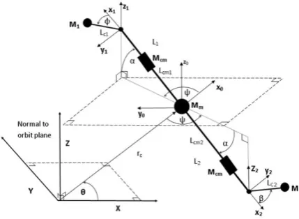
Component positions are defined relative to the orbit plane. Individual mass moments of inertia (MOI) are determined locally, and with the parallel axis theorem to the centre of mass. Due to its significant cross-sectional area, the tether is discretised when deriving its mass moment of inertia. Total kinetic, Ti
and potential, Ui energies of each component, and
propulsion braid, are also defined.
Fig. 18. 3D schematic representation of proposed lunavator
Seven representative equations of motion can be derived by substituting the potential and kinetic energies into Lagrange’s Equation.
𝑑𝑑𝑑𝑑𝑑𝑑
[
𝛿𝛿𝑞𝑞𝛿𝛿𝛿𝛿 𝑖𝑖,] −
𝛿𝛿𝛿𝛿 𝛿𝛿𝑞𝑞𝑖𝑖
+
𝛿𝛿𝛿𝛿
𝛿𝛿𝑞𝑞𝑖𝑖
= 𝑄𝑄
𝑖𝑖 (6) where 𝑞𝑞𝑖𝑖= {𝐿𝐿𝑐𝑐1, 𝐿𝐿𝑐𝑐2, ∅, 𝛽𝛽, 𝐿𝐿𝑐𝑐𝑐𝑐1, 𝐿𝐿𝑐𝑐𝑐𝑐2, 𝜑𝜑}By defining cable extension as a simple quadratic function, all seven dependent variables can be related to 𝜑𝜑, and the model reduced to a single equation of motion for subsequent dynamic study.
0 1000 2000 3000 4000 5000 6000 7000
- 10 000 - 8000 - 6000 - 4000 - 2000 0
time
z[
t]
(m
[image:6.595.317.532.436.593.2]It was found that a proposed 580km tether (with 2 tonne payloads) required a motor torque of 1000 MNm, with a motor mass of 1000 tonnes, to result in continuous spin (Figure 19). Smaller torque values cause in-plane tether libration wherein the lunavator cannot overcome its inertial elements (Figure 20). Alternatively, a 100km tether is found to perform adequately with 25 MNm of torque and a motor mass of 25 tonnes. Differential positioning of crawler masses may be used to ascend the tether during normal orbit, and descend during the payload transfer phases. Further work will determine the viability of such an approach.
[image:7.595.60.272.419.553.2]Fig. 19. Continuous spin of 580km tether with 2,000kg payloads, 1,000 tonne motor mass, 1000 MNm torque
Fig. 20. In-plane libration of 580km tether with 2,000kg payloads, 1,000 tonne motor mass, 145 MNm torque
6. Deployment of a Short Tether from
an Earth Orbiter for Sample Return
Momentum exchange space tethers can be used to deorbit payloads from a vehicle travelling in a low Earth orbit. As demonstrated by the YES2 mission of 2007 [9], a payload can be swung in libration from an Earth orbiter and if released at the right moment a retrograde velocity can be transferred to it causing it to have insufficient velocity to remain in orbit, and therefore fall to the Earth.In order to analyse accurately the requirements for deorbiting payloads of different mass and shape, a computer program was created which was capable of analysing the libration of an Earth orbiter in LEO
connected to a payload via a tether. The program aimed to analyse the movements of a planar representation of a tether system comprising two masses and a solid cylinder representing a tether. This planar system is shown in Figure 21. The equation of motion for the system can be derived using the Lagrange equation as shown in Equation (6), and just as in previous sections.
Fig. 21. Planar tether system
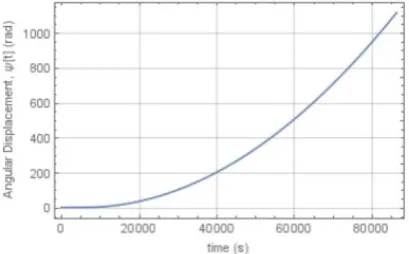
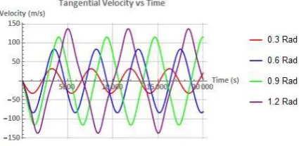
The equation of motion is inherently nonlinear and can be numerically integrated for different initial conditions. The angular displacement, angular velocity and tangential velocity of the payload are plotted so that the behaviour of a librating tether system in LEO can be analysed. Examples of the plots from this exercise are shown in Figures 22, 23 and 24.
Fig. 22. An example of the angular displacement vs time chart for a tether system.
[image:7.595.316.548.432.536.2]Fig. 23. An example of the angular velocity vs time chart for a tether system
Fig. 24. An example of the tangential velocity vs time chart for a tether system.
Conclusions
Motorised tethers potentially offer clean, green, reusable propulsion in space. Many practical (equatorial and even polar) orbits could in principle be accommodated. The dynamics of space tethers are complicated, and so robust GNC and compensation propulsion will be required in all practical scenarios, particularly in asymmetrical conditions, to safeguard against failure. It may be still possible to operate a motorised momentum exchange tether on a pre-specified orbit after catastrophic payload loss - if controlled axial thrust is provided by suitable emergency on-board payload propellant. METs can almost certainly be used for small sample return from an Earth orbiter. A Lunavator with reeled end-cables may offer a practical solution for smooth lunar payload delivery and retrieval. Both these applications are currently receiving further attention, with the goal of integrating them within practical mission architectures in the near future.
References
1. M.P. Cartmell, Generating Velocity
Increments by means of a Spinning Motorised Tether, AIAA-98-3739, Cleveland, Ohio, USA (1998)
2. M.P. Cartmell, D.J. McKenzie, Progress in Aerospace Sciences, 44, 1-21 (2008)
3. S.W.Ziegler, The Rigid Body Dynamics of Tethers in Space, PhD Thesis, University of Glasgow (2003)
4. D.J. McKenzie, The Dynamics of Tethers and Space-Webs PhD Thesis, University of Glasgow (2010)
5. N.A. Ismail, The Dynamics of a Flexible Motorised Momentum Exchange Tether (MMET), PhD Thesis, University of Glasgow (2011)
6. M.P. Cartmell, C.R. McInnes, Modern Astrodynamics, Chapter 7, Elsevier Astrodynamics Series, Edited by P.Gurfil (2006)
7. C. Murray, Continuous Earth-Moon Payload Exchange using Motorised Tethers with Associated Dynamics, PhD Thesis, University of Glasgow (2011)
8. G. Fu, Research on Asymmetrical Motorised Momentum Exchange Tether, Final Research Report, Department of Mechanical Engineering, University of Sheffield, (2016) 9. Y. Chen, R. Huang, X. Ren, L. He, Y. He,
[image:8.595.59.272.233.337.2]