MOBILE SIGNAL CANCELLATION DEVICE
SITI NORMI BT ZABRI @ SUHAIMI
RESEARCH VOTE NO: PJP/2009/FKEKK (11 D) S547
Fakulti Kejuruteraan Elektronik dan Kejuruteraan Komputer Universiti Teknikal Malaysia Melaka
MOBILE SIGNAL CANCELLATION DEVICE
(Keywords: Mobile phone, signal cancellation device, block signal)
The number of users of mobile communication devices is rapidly increasing nowadays, proving the communications industry is very important. The use of mobile phones however generates electromagnetic radiation which then scatters to surrounding. The resulting radiation can generate problems and damages to human and surrounding. Sometimes, there is a growing demand for controlling the use of cellular phones in public places such as religious places, examination halls, libraries, and others. Therefore, it is important to block signal to and from mobile phone at certain areas. The overall aim of this project is to design and built a signal cancellation device for mobile phones. The device provides the advantage in preventing mobile phone from receiving and transmitting RF signal to base station.
Key Researchers:
Cik Siti Normi bt Zabri @ Suhaimi (Head) Pn. Noor Shahida bt Mohd Kasim
Mr. David Yap Fook Weng
E-mail: Tel. No.: Vote No.:
normi@utem.edu.my 06-5552091
ACKNOWLEDGEMENTS
Praise to Allah S.W.T, the most Merciful and the Benevolent who has given us
the strength and His blessing to prepare and complete this project which was supported
by research fund ofUniversiti Teknikal Malaysia Melaka (UTeM).
On this opportunity, we would like to express our gratitude to the Faculty of
Electronic & Computer Engineering (FKEKK) which encourages their staff to involve in
researches and publications.
Last but not least, our deepest appreciation goes to those involve directly or
TABLE OF CONTENTS
ABSTRACT ... .i
ACKNOWLEDGEMENTS ... ii
LIST OF FIGURES ... v
LIST OF ABBREVIATIONS ... vi
CHAPTER 1 ... 1
1.1 Introduction ... 1
1.2 Objectives ... 2
1.3 Problem statement ... 2
1.4 Project Scopes ... 3
1.5 Technical Parameters ... 4
CHAPTER2 ... 5
2.1 Introduction ... 5
2.2 Mobile Signal Cancellation Device ... 5
2.2.1 Mobile Signal Cancellation Device Operation ... 6
2.3 Mobile Signal Cancellation Device Techniques ... 7
2.3.1 Type "A" Device: JAMMERS ... 7
2.3.2 Type "B" Device: INTELLIGENT CELLULAR DISABLERS ... 7
2.3.3 Type "C" Device: INTELLIGENT BEACON DISABLERS ... 8
2.3.4 Type "D" Device: DIRECT RECEIVE & TRANSMIT JAMMERS ... 9
2.3.5 Type "E" Device: EMI SHIELD- PASSIVE JAMMING ... 10 2.4 GSM- MOBILE JAMMING REQUIREMENTS ... 10
2.5 DESIGN AND IMPLEMENTATION OF GSM MOBILE JAMMER ... 13
2.5.1 IF-Section ... 14
2.5.1.1 Triangular Wave Generator ... 15 2.5 .1.2 Noise Generator ... 17 2.5 .1.3 Signal Mixer and DC-Offset Circuits ... 19
2.5.2 RF-Section ... 21
2.5.2.2 RF Power Amplifier ... 24
2.5.2.3 Antenna ... 27
CHAPTER 3 ... 31
3.1 Power supply section ... 31
3.2 IF-Section ... 32
3.3 RF-Section ... 35
CHAPTER 4 ............................... 40
4.1 Introduction ... 40
4.2 IF Section ... 40
4.2.2 RF-Section ... 42
CHAPTER 5 .................................... ...... 46
5.1 Conclusion ... 46
5.2 Future Recommendation ... 46
LIST OF FIGURES
[image:6.564.69.511.58.667.2]TITLE PAGE
Figure 2.1: Block diagram of GSM Jammer ... 14
Figure 2.2: Block diagram ofiF Section ... 15
Figure 2.3: Timer connected as Oscillator ... 15
Figure 2.4: The output voltage on Cext ... 17
Figure 2.5: Noise Generator Schematic ... 18
Figure 2.6: White-noise generator output spectrum ... 18
Figure 2.7: OP-Amp Summer Circuit ... 19
Figure 2.8: Positive Diode-Clamper with bias ... 19
Figure 2.9: Circuit Schematic ofiF Section ... 20
Figure 2.10: Block Diagram ofRF-Section ... 21
Figure 2.11: Internal Block Diagram of MAX2623 IC ... 24
Figure 2.12: Typical biasing Configuration for the MAR-4SM ... 25
Figure 2.13: Design ofMAR-4SM on AppCAD ... 26
Figure 2.14: T-Network Attenuator ... 26
Figure 2.15: RF PCB Layout ... 28
Figure 2.16: Circuit Schematic ofRF Section ... 29
Figure 3.1: Circuit Schematic ofPower Supply Section ... .31
Figure 3.2: Circuit Schematic of IF Section ... 33
Figure 3.3: Circuit Schematic ofiF Section on the software of Protei DXP 2004 ... 34
Figure 3.4: Conversion of the IF Section to the PCB Board ... 34
Figure 3.5: Circuit Schematic ofRF Section ... 35
Figure 3.6: Circuit Schematic ofRF Section on the software of Protei DXP 2004 ... 36
Figure 3.7: Convert the RF Section to the PCB Board ... .37
Figure 3.8 Summarized workflow of etching process ... 39
Figure 4.1: Power supply circuit. ... 40
Figure 4.2 Circuit of IF Section ... 41
Figure 4.3 Output Result of IF Section ... .42
Figure 4.4: Block Diagram ofRF-Section ... .43
Figure 4.5 Circuit construction ofRF Section ... .43
Figure 4.6 Output result of RF Section ... .44
LIST OF ABBREVIATIONS
GSM Global System for Mobile
RF Radio Frequency
AMPS Advanced Mobile Phone System
COMA Code Division Multiple Access
FDMA Frequency Division Multiple Access
TDMA Time Division Multiple Access
PCS Personal Communication Service
DCS Distributed Controlled System
iDEN Integrated Digital Enhanced Network
EMI Electromagnetic interference
BSS Base Station Subsystem
BTS Base Transceiver Station
SNR Signal to Noise Ratio
RACH Random Access Channel
vco
Voltage Controlled OscillatorIC Integrated Circuit
CHAPTER1
PROJECT BACKGROUND
1.1 Introduction
A mobile signal cancellation device is a device that transmit signal on the same
frequency at which the GSM system operates, the jamming success when the mobile
phones in the area where the device is located are disabled. Sometimes, this device is also
known as mobile jammer.
Military initiated the development and utilized communication jamming devices.
Where tactical commanders used RF communications to exercise control of their forces,
an enemy has interest in those communications. This interest comes from the
fundamental area of denying the successful transport of the information from the sender
to the receiver. Nowadays the signal cancellation devices are becoming civilian products
rather than electronic warfare devices, since with the increasing number of the mobile
phone user the need to disable mobile phone in specific places where the ringing of cell
phone would be disruptive has increased(Jisrawi). These places included worship places,
university lecture rooms, libraries, concert halls, meeting rooms, and other places where
silence is appreciated.
Mosques are obvious example for the places that mobile signal cancellation
device would be a great solution, although mosques normally asks from prayers to
disable their mobile phone during the prayer u, but some people forget and the ringing
1.2 Objectives
These are the main objectives of conducting this project:
• To develop a mobile signal cancellation device that can detect and restrict mobile
phone signal which is 1 0 - 20m and up in diameter and 20 meters far from
transmitting station.
• To block all kinds of mobile phones ringing sound at certain places such as banks,
mosques, libraries, movie theaters, meeting rooms and others.
• To disable effectively mobile phones within the defined regulated zones without
causing any interference to other communication.
1.3 Problem statement
Mobile phones are widely used these days and well known for its property as a
good medium of communication. However, there are certain areas where the use of
mobile phones would be particularly prohibited or where the radio transmissions are
dangerous.
Indeed, while the inappropriate ringing, and unreasonably loud conversations can
be annoying, the sense of powerless, or lack of control increase the frustration. As a
result, there have been some attempts to control cell phone use, to create 'safe zones' of
Hertzian space. In some cities, trains and trolleys have designated "quiet cars," for people
who prefer no cell usage.
The easiest and most common technique to curbing cell use is requesting courtesy
for others. It is somewhat convenient for some businesses and places of worship and also
other restricted areas, rather than request polite cell-use, simply disable all cell phones
from being used.
This project will investigate and design the device that will be used for canceling
1.4 Project Scopes
Cell phones are full-duplex devices, which mean they use two separate
frequencies, one for talking and one for listening simultaneously. Some devices block
only one of the frequencies used by cell phones, which has the effect of blocking both.
The phone is tricked into thinking there is no service because it can receive only one of
the frequencies.
The mobile signal cancellation device will be designed to:
• restrict the mobile phone signal which 10m-20m & up in diameter and 20 meters
far from the transmitting station.
• shield only mobile phone signals, but has no influence on other electronic
equipments, audio equipments and human bodies.
• be easily installed and the connector plug is the only one that is needed to install.
To jam a cell phone, a device that broadcasts on the correct frequencies is needed.
Although different cellular systems process signals differently, all cell-phone networks
use radio signals that can be interrupted. The device's effect can vary widely based on factors such as proximity to towers, indoor and outdoor setting, presence of buildings and
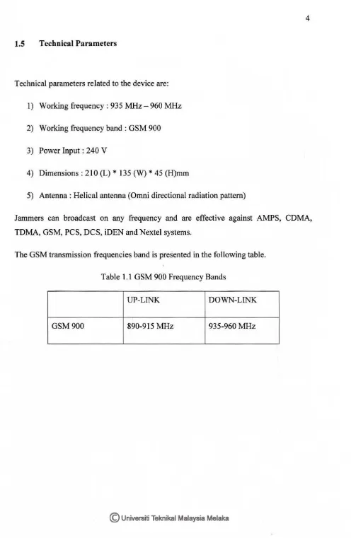
1.5 Technical Parameters
Technical parameters related to the device are:
1) Working frequency : 935 MHz-960 MHz
2) Working frequency band: GSM 900
3) Power Input: 240 V
4) Dimensions: 210 (L) * 135 (W) * 45 (H)mm
5) Antenna: Helical antenna (Omnidirectional radiation pattern)
Jammers can broadcast on any frequency and are effective against AMPS, CDMA,
TDMA, GSM, PCS, DCS, iDEN and Nextel systems.
[image:11.564.50.546.40.801.2]The GSM transmission frequencies band is presented in the following table.
Table 1.1 GSM 900 Frequency Bands
UP-LINK DOWN-LINK
CHAPTER2
LITERATURE REVIEW
2.1 Introduction
This chapter explains the literature review involved regarding the project title.
Basic definition and operation of mobile signal cancellation device are described.
2.2 Mobile Signal Cancellation Device
Also known as mobile jammer, a mobile signal cancellation device is a transmitter used
to broadcast electromagnetic signals capable of blocking frequencies used by
cellular/PCS systems. When active in a certain area, the mobile jammer will prevent any
cellular/PCS system from communicating with the base station, and by this prohibiting
all incoming and outgoing calls (Azza, Hijazi, & Mahmoudy).
Jamming devices overpower the cell phone by transmitting a signal on the same
frequency as the cell phone and at a high enough power that the two signals collide and
cancel each other out. Cell phones are designed to add power if they experience low-level
interference, so the jammer must recognize and match the power increase from the
phone. Cell phones are full-duplex devices, which mean they use two separate
frequencies, one for talking and one for listening simultaneously. Some jammers block
only one of the frequencies used by cell phones, which has the effect of blocking both
(Wollenhaupt, 2005). The phone is tricked into thinking there is no service because it can
Less complex devices block only one group of frequencies, while sophisticated
jammers can block several types of networks at once to head off dual-mode or tri-mode
phones that automatically switch among different network types to find an open signal.
Some of the high-end devices block all frequencies at once and others can be tuned to
specific frequencies (Wollenhaupt, 2005).
2.2.1 Mobile Signal Cancellation Device Operation
To jam a mobile phone, what is needed is a device that broadcasts on the correct
frequencies. Although different cellular systems process signals differently, all cell-phone
networks use radio signals that can be interrupted. GSM, used in digital cellular and
PCS-based systems, operates in the 900-MHz and 1800-MHz bands in Europe and Asia and in
the 1900-MHz (sometimes referred to as 1.9-GHz) band in the United States. Jammers
can broadcast on any frequency and are effective against AMPS, CDMA, TDMA, GSM,
PCS, DCS, iDEN and Nextel systems (Wollenhaupt, 2005). Old-fashioned analog cell
phones and today's digital devices are equally susceptible to jamming. Disrupting a cell
phone is the same as jamming any other type of radio communication. A cell phone
works by communicating with its service network through a cell tower or base station.
Cell towers divide a city into small areas, or cells. As a cell phone user drives down the
street, the signal is handed from tower to tower.
A jamming device transmits on the same radio frequencies as the cell phone,
which is 900MHz disrupting the communication between the phone and the cell-phone
base station in the town. The power of the jammer's effect can vary widely based on
factors such as proximity to towers, indoor and outdoor settings, presence of buildings
and landscape, even temperature and humidity play a role. There are concerns that
crudely designed jammers may disrupt the functioning of medical devices such as
pacemakers. However, like cell phones, most of the devices in common use operate at
2.3 Mobile Signal Cancellation Device Techniques
Five types of devices are known to have been developed (or being considered for
development) for preventing mobile phones' communications in certain specified
locations (RABC):
2.3.1 Type "A" Device: JAMMERS
In this device we overpower cell phone's signal with a stronger signal, This type of
device comes equipped with several independent oscillators transmitting 'jamming
signals' capable ofblocking frequencies used by paging devices as well as those used by
cellular/PCS systems' control channels for call establishment. When active in a
designated area, such devices will (by means of RF interference) prevent all pagers and
mobile phones located in that area from receiving and transmitting calls. This type of
device transmits only a jamming signal and has very poor frequency selectivity, which
leads to interference with a larger amount of communication spectrum than it was
originally intended to target. Technologist Jim Mahan said, "There are two types. One is
called brute force jamming, which just blocks everything. The problem is, it's like
power-washing the airwaves and it bleeds over into the public broadcast area. The other puts out
a small amount of interference, and you could potentially confine it within a single cell
block. You could use lots of little pockets of small jamming to keep a facility under
control."
2.3.2 Type "B" Device: INTELLIGENT CELLULAR DISABLERS
Unlike jammers, Type "B" devices do not transmit an interfering signal on the
control channels. The device, when located in a designated 'quiet' area, functions as a
'detector'. It has a unique identification number for communicating with the cellular base
station. When a Type "B" device detects the presence of a mobile phone in the quiet
room; the 'filtering' (i.e. the prevention of authorization of call establishment) is done by
When the base station sends the signaling transmission to a target user, the device
after detecting simultaneously the presence of that signal and the presence of the target
user, signals the base station that the target user is in a 'quiet' room; therefore, do not
establish the communication. Messages can be routed to the user's voice- mail box, if the
user subscribes to a voice-mail service. This process of detection and interruption of call
establishment is done during the interval normally reserved for signaling and
handshaking. For 'emergency users', the intelligent detector device makes provisions for
designated users who have emergency status. These users must pre-register their phone
numbers with the service providers. When an incoming call arrives, the detector
recognizes that number and the call are established for a specified maximum duration,
say two minutes. The emergency users are also allowed to make out going calls.
Similarly, the system is capable of recognizing and allowing all emergency calls routed to
"911 "0
It should be noted that the Type "B" detector device being an integral part of the
cellular/PCS systems, would need to be provisioned by the cellular/PCS service providers
or provisioned by a third-party working cooperatively with full support of the
cellular/PCS service providers.
2.3.3 Type "C" Device: INTELLIGENT BEACON DISABLERS
Unlike jammers, Type "C" devices do not transmit an interfering signal on the
control channels. The device, when located in a designated 'quiet' area, functions as a
'beacon' and any compatible terminal is instructed to disable its ringer or disable its
operation, while within the coverage area of the beacon. Only terminals which have a
compatible receiver would respond and this would typically be built on a separate
technology from cellular/PCS, e.g., cordless wireless, paging, ISM, Bluetooth. On
leaving the coverage area of the beacon, the handset must re-enable its normal function.
This technology does not cause interference and does not require any changes to
separate receiver for the beacon system from the cellular/PCS receiver. It will not prevent
normal operation for incompatible legacy terminals within a "quiet" coverage area, thus
effective deployment will be problematic for many years.
While general uninformed users would lose functionality, pre-designated
"emergency" users could be informed of a "bypass terminal key sequence" to inhibit
response to the beacon. Assuming the beacon system uses a technology with its own
license (or in the license exempt band), no change to the regulations are needed to deploy
such a system. With this system, it would be extremely difficult to police misuse of the
"bypass key sequence" by users.
2.3.4 Type "D" Device: DIRECT RECEIVE & TRANSMIT JAMMERS
This jammer behaves like a small, independent and portable base station, which
can directly interact intelligently or unintelligently with the operation of the local mobile
phone. The jammer is predominantly in receiving mode and will intelligently choose to
interact and block the cell phone directly if it is within close proximity of the jammer.
This selective jamming technique uses a discriminating receiver to target the
jamming transmitter. The benefit of such targeting selectivity is much less
electromagnetic pollution in terms of raw power transmitted and frequency spectrum
from the jammer, and therefore much less disruptive to passing traffic. The jam signal
would only stay on as long as the mobile continues to make a link with the base station,
otherwise there would be no jamming transmission - the technique forces the link to
break or unhook and then it retreats to a passive receive mode again.
This technique could be implemented without cooperation from PCS/cellular
providers, but could negatively impact PCS/cellular system operation. This technique has
an added advantage over Type B in that no added overhead time or effort is spent
negotiating with the cellular network. As well as Type B, this device could discriminate
2.3.5 Type "E" Device: EMI SHIELD -PASSIVE JAMMING
This technique is using EMI suppression techniques to make a room into what is
called a Faraday cage. Although labor intensive to construct, the Faraday cage essentially
blocks, or greatly attenuates, virtually all electromagnetic radiation from entering or
leaving the cage or in this case a target room.
With current advances in EMI shielding techniques and commercially available
products one could conceivably implement this into the architecture of newly designed
buildings for so-called "quiet-conference" rooms. Emergency calls would be blocked
unless there was a way to receive and decode the 911 transmissions, pass by coax outside
the room and re-transmitted.
This passive configuration is currently legal in Canada for any commercial or
residential location insofar as DOC Industry Canada is concerned, however municipal or
provincial building code by- laws may or may not allow this type of construction.
2.4 GSM- MOBILE JAMMING REQUIREMENTS
Jamming objective is to inject an interference signal into the communications
frequency so that the actual signal is completely submerged by the interference. It is
important to notice that transmission can never be totally jammed -jamming hinders the
reception at the other end. The problem here for the jammer is that only transmitters can
be found using direction finding and the location of the target must be a specific location,
usually where the jammer is located and this is because the jamming power is never
infinite. Jamming is successful when the jamming signal denies the usability of the
communications transmission. In digital communications, the usability is denied when
the error rate of the transmission cannot be compensated by error correction. Usually a
successful jamming attack requires that the jammer power is roughly equal to signal
power at the receiver. The effects of jamming depend on the jamming-to-signal ratio
{1/S), modulation scheme, channel coding and interleaving of the target system.
] Pj Gjr Grj R2tr Lr Br
-S Pt Gtr Grt R2jr Lj Bj
J
s
Pj= jammer power P1= transmitter powerGjr= antenna gain from jammer to receiver
Grj= antenna gain from receiver to Jammer
Gtr= antenna gain from transmitter to receiver
Grt= antenna gain from receiver to transmitter
Br= communications receiver bandwidth
Bj= jamming transmitter bandwidth
Rtr= range between communications transmitter and receiver
Rjt= range between jammer and communications receiver
Lj= jammer signal loss (including polarization mismatch)
Lr= communication signal loss
The above equation indicates that the jammer Effective Radiated Power, which is
the product of antenna gain and output power, should be high if jamming efficiency is
required. On the other hand, in order to pr event jamming, the antenna gain toward the
communication partner should be as high as possible while the gain towards the jammer
should be as small as possible. As the equation shows, the antenna pattern, the relation
between the azimuth and the gain, is a very important aspect in jamming.
Also as we know from Microwave and shown in the equation distance has a
strong influence on the signal loss. If the distance between jammer and receiver is
doubled, the jammer has to quadruple its output in order for the jamming to have the
same effect. It must also be noted here the jammer path loss is often different from the
communications path loss; hence gives jammer an advantage over communication
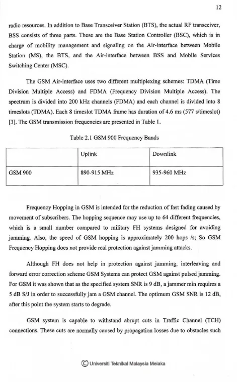
radio resources. In addition to Base Transceiver Station (BTS), the actual RF transceiver, BSS consists of three parts. These are the Base Station Controller (BSC), which is in charge of mobility management and signaling on the Air-interface between Mobile Station (MS), the BTS, and the Air-interface between BSS and Mobile Services Switching Center (MSC).
The GSM Air-interface uses two different multiplexing schemes: TDMA (Time Division Multiple Access) and FDMA (Frequency Division Multiple Access). The spectrum is divided into 200 kHz channels (FDMA) and each channel is divided into 8 timeslots (TDMA). Each 8 timeslot TDMA frame has duration of 4.6 ms (577 s/timeslot) [3]. The GSM transmission frequencies are presented in Table 1.
Table 2.1 GSM 900 Frequency Bands
Uplink Downlink
GSM900 890-915 MHz 935-960 MHz
Frequency Hopping in GSM is intended for the reduction of fast fading caused by movement of subscribers. The hopping sequence may use up to 64 different frequencies, which is a small number compared to military FH systems designed for avoiding jamming. Also, the speed of GSM hopping is approximately 200 hops /s; So GSM Frequency Hopping does not provide real protection against jamming attacks.
Although FH does not help in protection against jamming, interleaving and forward error correction scheme GSM Systems can protect GSM against pulsed jamming. For GSM it was shown that as the specified system SNR is 9 dB, a jammer min requires a 5 dB S/J in order to successfully jam a GSM channel. The optimum GSM SNR is 12 dB, after this point the system starts to degrade.
[image:19.558.41.512.50.812.2]as bridges. Usually another cell could be used to hold communication when the original
BTS has disconnected. The GSM architecture provides two solutions for this: first
handover when the connection is still available, second call reestablishment when the
original connection is totally lost. Handover decisions are made based on transmission
quality and reception level measurements carried out by the MS and the BTS. In jamming
situations call re-establishment is probably the procedure the network will take in order to
re-connect the jammed TCH.
It is obvious that downlink jamming (i.e. Jamming the mobile station
'handset'(receiver) is easier than uplink, as the base station antenna is usually located far
away from the MS on a tower or a high building. This makes it efficient for the jammer
to overpower the signal from BS. But the Random Access Channel (RACH) control
channels of all BTSs in the area need to be jammed in order to cut off transmission. To
cut an existing connections, the jamming has to last at least until the call re-establishment
timer at the MSC expires and the connection is released, which means that an existing
call can be cut after a few seconds of effective jamming.
The GSM RACH random access scheme is very simple: when a request is not
answered, the mobile station will repeat it after a random interval. The maximum number
of repetitions and the time between them is broadcast regularly. After a MS has tried to
request service on RACH and has been rejected, it may try to request service from
another cell. Therefore, the cells in the area should be jammed. In most cases, the
efficiency of a cellular jamming is very difficult to determine, since it depends on many
factors, which leaves the jammer confused.
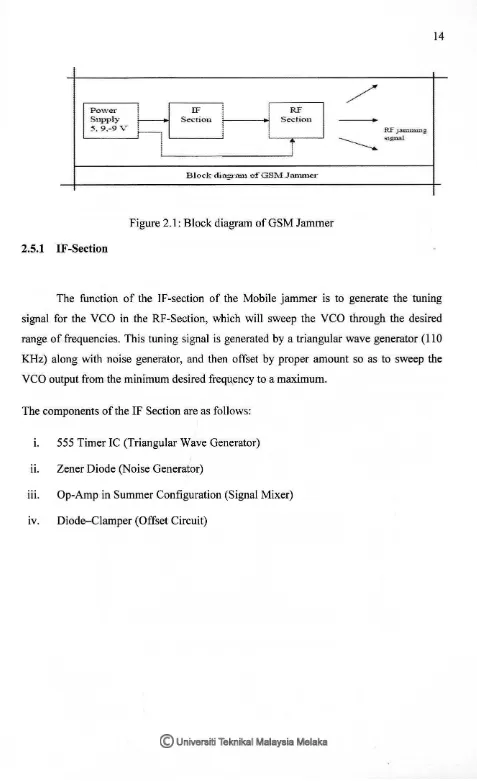
2.5 DESIGN AND IMPLEMENTATION OF GSM MOBILE JAMMER
The Implementation of type "A" JAMMER is fairly simple, the block diagram for
this type is shown in Figure 2.1, it shows the main parts which are: RF -section,
Power
Supply
5. 9.-9 v
2.5.1 IF -Section
IF It
Section t--- - + l
J
RF
Section
T
[image:21.561.44.521.31.812.2]Block diagnuu o:fGSM Jammer
Figure 2.1: Block diagram of GSM Jammer
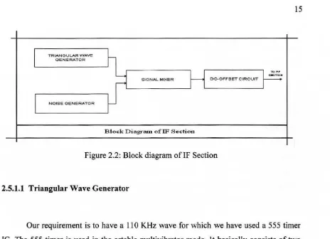
The function of the IF-section of the Mobile jammer is to generate the tuning
signal for the VCO in the RF-Section, which will sweep the VCO through the desired
range of frequencies. This tuning signal is generated by a triangular wave generator (110
KHz) along with noise generator, and then offset by proper amount so as to sweep the
VCO output from the minimum desired frequ_ency to a maximum.
The components of the IF Section are as follows:
1. 555 Timer IC (Triangular Wave Generator)
ii. Zener Diode (Noise Generator)
iii. Op-Amp in Summer Configuration (Signal Mixer)
TRIANOULAR WAVE
OENERATOR
NOISE GENERATOR
SIGNAL MIXER DC.· OFFSET C.IRC.UIT
[image:22.561.59.530.51.812.2] [image:22.561.64.528.55.391.2]Block Diagratn ofiF Section
Figure 2.2: Block diagram of IF Section
2.5.1.1 Triangular Wave Generator
Our requirement is to have a 110 KHz wave for which we have used a 555 timer
IC. The 555 timer is used in the astable multivibrator mode. It basically consists of two
comparators, a flip-flop, a discharge transistors and a resistive voltage divider to set the
voltages at different comparator levels. The Figure (2.3) shows the 555 timer connected
to operate in the astable multivibrator mode as a non-sinusoidal oscillator.
The 555 timer consists basically of two comparators, a flip-flop, a discharge
transistor, and a resistive voltage divider. The resistive divider is used to set the voltage
comparator levels all three comparator levels. A 555 timer connected to operate in the
astable mode as a free-running nonsinusoidal oscillator (astable multivibrator).
The threshold input is connected to the trigger input. The external components R~, R2&Cex Form the timing circuit that sets the frequency of oscillation. The 0.01uF capacitor connected to the control input is strictly for decoupling and has no effect on the
operation; in some cases it can be left off. Initially, when the power is turned on, the
capacitor Cex is uncharged and thus the trigger voltage (pin 2) is at 0 V. This causes the
output of the lower comparator to be high and the output of the upper comparator to be low, forcing the output of the flip-flop, and thus the base of Q, low and keeping the transistor off. Now, Cext begins charging through R1& R2 (to obtain 50% duty cycle, one
can connect a diode parallel with R2 and choose R1= R2).
When the capacitor voltage reaches 113Vcc, the lower comparator switches to its
low output state, and when the capacitor voltage reaches 2/3 V cc the upper comparator switches to its high output state. This resets the flip flop causes the base of Qd to go high,
and turns on the transistor. This sequence creates a charge path for the capacitor through
R2 and the transistor, as indicated. The cap now begins to discharge, causing the upper comparator to go low. At the point whet capacitor discharges down to 1/3Vcc, the lower
comparator switches high, setting the flip flop, which makes the base of Qd low and turns off the transistor. Another charging cycles begins, and the entire process repeats. The
result is a rectangular wave output whose duty cycle depends on the values ofRl and R2.
The frequency of oscillation is given by the following formula
f=
1.44(Rl+R2) Cext
Using the above equation for frequency equal 110 KHz, one can found the values
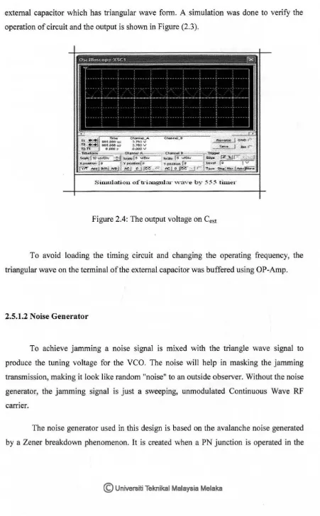
external capacitor which has triangular wave fonn. A simulation was done to verify the operation of circuit and the output is shown in Figure (2.3).
[image:24.561.58.509.84.812.2]s,uutlatioo ottriangular \.\"aVe by 555 tliner
Figure 2.4: The output voltage on Cext
To avoid loading the timing circuit and changing the operating frequency, the
triangular wave on the tenninal of the external capacitor was buffered using OP-Amp.
2.5.1.2 Noise Generator
To achieve jamming a noise signal is mixed with the triangle wave signal to
produce the tuning voltage for the VCO. The noise will help in masking the jamming
transmission, making it look like random "noise" to an outside observer. Without the noise
generator, the jamming signal is just a sweeping, unmodulated Continuous Wave RF
carrier.