SUPERVISOR’S VERIFICATION
I hereby admit that have read this report and from my point of view this report is enough in term of scope and quality for purpose for awarding
Bachelor of Degree in Mechanical Engineering (Thermal-Fluid)
STUDY OF OPTIMIZING HX1 CAR AIR CONDITIONING HEAT EXCHANGER BY USING CFD METHOD
ALI ILMAN BIN ABDULLAH @ SUDIN
This report presented to fulfill the requirement in term to obtain Bachelor of Degree in Mechanical Engineering (Thermal-Fluid)
Faculty of Mechanical Engineering
iii
DECLARATION
“I admit this report has been written by me myself except for some quotation that has been noted well for each of them”
Signature : …...
iv
DEDICATION
v
ACKNOWLEDGEMENT
Firstly, I would to give my greatest gratitude and appreciation to my supervisor of this Projek Sarjana Muda (PSM), Encik Faizil bin Wasbari for his guidance, support and practical advisers throughout the entire project. I would also like to thanks to all the members under the guidance of Encik Faizil for their teamwork and contribution towards the success of the project.
In addition, I could not execute this project smoothly without my roommate’s help, Ahmad Syauqi bin Ahmad Shukri, who gave me a lot of information regarding the completion this project. I also like to give my appreciation to my family, which support me for completion this project. Lastly, special thanks to each and every individual who help me throughout the efforts of this report be in form of encouragement and advice.
vi
ABSTRACT
.
vii
ABSTRAK
viii
TABLE OF CONTENTS
TITLE PAGE
SUPERVISOR’S VERIFICATION i
DECLARATION iii
DEDICATION iv
ACKNOWLEDGEMENT v
ABSTRACT vi
ABSTRAK vii
TABLE OF CONTENTS viii
LIST OF TABLES 1
LIST OF FIGURES 2
LIST OF SYMBOLS 5
CHAPTER 1 6
INTRODUCTION 6
1.1 Background Study 6
1.2 Problem Statement 6
1.3 Objectives 7
ix
CHAPTER 2 8
LITERATURE REVIEW 8
2.1 Introduction 8
2.2 Refrigeration Cycles 8
2.3 Car air conditioning 10
2.4 Heat Exchanger 20
2.5 Mechanism of Heat Transfer 27
2.6 CFD 30
2.7 Study of Efficiency of Double Pipe Internal Heat Exchanger for Car Air
Conditioning System 31
CHAPTER 3 33
METHODOLOGY 33
3.1 Introduction 33
3.2 Literature Review 34
3.3 Draw Current HX1 36
3.4 Run First Simulation 37
3.5 Validation 39
3.6 Design Improvement 41
3.7 Run Second Simulation 41
3.8 Data Collection 45
3.9 Comparison 48
x
CHAPTER 4 54
RESULT 54
4.1 Simulation 1 54
4.2 Simulation 2 55
4.3 Simulation 3 56
4.4 Simulation 4 57
4.5 Simulation 5 58
4.6 Simulation 6 59
4.7 Simulation 7 60
4.8 Simulation 8 61
4.9 Simulation 9 62
4.10 Simulation 10 63
CHAPTER 5 64
DATA ANALYSIS 64
5.1 Validation 64
5.2 Cluster 1 (number of tubes) 65
5.3 Cluster 2 (flow direction and configuration) 67
5.4 Cluster 3 (pipe width) 67
xi
CHAPTER 6 72
DISCUSSION 72
6.1 Validation 72
6.2 Cluster 1 (number of tubes) 73
6.3 Cluster 2 (flow direction and configuration) 74
6.4 Cluster 3 (pipe width) 76
6.5 Cluster 4 (material) 77
6.6 Choosing HX2 78
6.7 Comparing HX1 and HX2 78
CHAPTER 7 87
CONCLUSION AND RECOMMENDATION 87
7.1 Conclusion 87
7.2 Recommendation 88
REFERENCE 89
APPENDIX A 91
GANTT CHART PSM 1 92
APPENDIX B 93
GANTT CHART PSM 2 94
APPENDIX C 95
1
LIST OF TABLES
NO TITLE PAGE
Table 2. 1 : The thermal conductivities of some materials at room temperature 29
Table 5. 1: Percentage deviation of HX1 experimental value and simulation value 64
Table 5. 2: Outlet temperature (number of tube) 66
Table 5. 3: Flow configuration and direction temperature outlet 67
Table 5. 4: Pipe width temperature diffrence 69
Table 5. 5: Temperature outlet (material) 71
2
LIST OF FIGURES
NO TITLE PAGE
Figure 2. 1 :Schematic of a single stage compression refrigeration cycle 9
Figure 2. 2 : Compressor 11
Figure 2. 3: Condenser 12
Figure 2. 4 : Evaporator 13
Figure 2. 5 : Orifice Tube 14
Figure 2. 6 : Common Expansion Valve Designs 16
Figure 2. 7 : (A) Open TXV, and (B) Closed TXV 16
Figure 2. 8 : Receiver Drier 17
Figure 2. 9 : Schematic Refrigeration Cycle with Suction/Liquid Heat Exchanger. 21
Figure 2. 10 : Shell and Tube Heat Exchanger 21
Figure 2.11 : Shell and Tube Heat Exchanger inside look 22
Figure 2.12 : Plate Heat Exchanger 23
Figure 2.13 : Exploded view of plate heat exchanger 24
Figure 2.14 : Tubular Heat Exchanger 26
Figure 2.15 : Tubular Heat Exchanger inside view 26
Figure 2. 16: Initial design for heat exchanger. 31
Figure 2. 17: Graph of result 32
Figure 3.1 : Process Flow Chart 35
Figure 3. 2 : Plan Drawing of HX1 Heat Exchanger 36
3
Figure 3.5 : Isometric Drawing of Internal HX1 Heat Exchanger 38 Figure 3. 6 : Experimental result on HX1 heat exchanger 40 Figure 3. 7: Schematic diagram for the experimental rig and temperature sensors
location 41
Figure 3. 8 : Horizontal line for high and low pressure] 47
Figure 3. 9 :p-H diagram 47
Figure 3. 10 : point location in heat exchanger HX1 48
Figure 3. 11: Cross section area of number of tubes in heat exchanger 49
Figure 3. 12 : Flow configuration and direction 50
Figure 3. 13: 30 mm cross section 51
Figure 3. 14 : 35 mm cross section 51
Figure 3. 15 : 40 mm cross section 52
Figure 4. 1: HX1 inside temperature (cold) 54
Figure 4. 2: HX1 outside temperature (hot) 54
Figure 4. 3: Single tube inside temperature (cold) 55
Figure 4. 4: Single Tube outside temperature (hot) 55
Figure 4. 5: Triple tubes inside temperature (cold) 56
Figure 4. 6: Triple tubes outside temperature (hot) 56
Figure 4. 7: Cross flow hot inside hot temperature 57
Figure 4. 8: Cross flow hot inside cold temperature 57
Figure 4. 9: Parallel flow cold inside cold temperature 58 Figure 4. 10: Parallel flow cold inside hot temperature 58 Figure 4. 11: Parallel flow hot inside cold temperature 59 Figure 4. 12: Parallel flow hot inside hot temperature 59
Figure 4. 13: 35 mm cold temperature 60
Figure 4. 14: 35 mm hot temperature 60
Figure 4. 15: 40 mm cold temperature 61
Figure 4. 16: 40 mm hot temperature 61
Figure 4. 17: Copper cold temperature 62
4
Figure 4. 19: Iron cold temperature 63
Figure 4. 20: Iron hot temperature 63
Figure 5. 1: Cold temperature (number of tube) 65
Figure 5. 2: Hot temperature (number of tube) 65
Figure 5. 3: Cold temperature (pipe width) 68
Figure 5. 4: Hot temperature (pipe width) 68
Figure 5. 5: Hot temperature (material) 70
Figure 5. 6: Cold temperature (material) 70
Figure 6. 1: Outer dimension of a heat exchanger 79
Figure 6. 2: Flow direction of hot and cold refrigerant 79
Figure 6. 3: 3D temperature profile for HX2 80
Figure 6. 4: 3D temperature profile for HX1 80
Figure 6. 5: Cold temperature HX1 and HX2 81
Figure 6. 6: Hot temperature HX1 and HX2 81
Figure 6. 7: Pressure drop for HX1 and HX2 82
Figure 6. 8: 3D pressure profile for HX1 83
Figure 6. 9: 3D pressure profile for HX2 83
Figure 6. 10: 3D velocity profile for HX1 84
Figure 6. 11: 3D velocity profile for HX2 85
5
LIST OF SYMBOLS
a = Acceleration, (m/s2) p
c = Thermal Capacity, (J/kg.K) F = Force, (N )
k = Thermal Conductivity, (W/m.K)
m = Mass, ()
p = Pressure, (N/m2) T = Temperature, (C)
C
T = Cold Temperature, (C) H
T = Hot Temperature, (C)
u = Velocity in x-direction, (m/ ) s v = Velocity in y-direction, (m/ ) s W = Width, (m)
CHAPTER 1
INTRODUCTION
1.1 Background Study
Air condition is somewhat a technology to control certain properties of air for the convenience of a person in a certain enclosed area. Mainly consist of HVAC which means heating, ventilating and air conditioning. Either used to cool the air, or heat it and also control the flow and humidity by an effective application of vaporization and condensation.
1.2 Problem Statement
Heat exchangers are widely used in industry both for cooling and heating large scale processes. Heat exchanger commonly applies in heating, ventilation and air conditioning (HVAC) systems, radiators, boilers and others. Heat exchanger can be added in the car air conditioning systems. With the existence of heat exchanger, it will increase the pressure drops in the air conditioning systems.
7
exchanger is a must in the system to avoid pollution and fuel inefficiency. Thus optimum flow in the heat exchanger plays a vital role in minimizing the air conditioning system’s energy consumption to save the environment.
1.3 Objectives
The objectives of this project are:
i. Profiling the current HX1 in term of pressure loss, velocity and flow.
ii. Compare the pressure loss, velocity and flow profile between HX1 with HX2
1.4 Scope
CHAPTER 2
LITERATURE REVIEW
2.1 Introduction
Heat exchanger is a device built for efficient heat transfer from one medium to another, whether the media are separated by solid wall so that they never mix, or the media are in contact. Heat exchanger widely used in refrigeration, air conditioning, power plants, space heating, and natural gas processing. One common example of a heat exchanger is the radiator in car, which the heat source, being a hot engine-cooling fluid, water transfers heat to air flowing through the radiator.
2.2 Refrigeration Cycles
9
pump and any air conditioning system that operates on a reversed Carnot cycle is called a Carnot refrigerator or Carnot heat pump.
Although the reversed cycle is ideal, most of the air conditioning system operates on an actual cycle that is quite different from the ideal cycle. The performance and efficiency is considerably lower and there are a lot more surrounding factors that must be calculated.
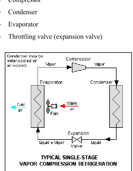
As there are four main components in a power cycle, there are also four main components in the refrigeration cycle. These components are
Compressor
Condenser
Evaporator
[image:20.612.207.442.321.622.2] Throttling valve (expansion valve)
10
These are the basic components of the cycle according to Figure 2.1. But in a contemporary refrigerant or cooling system, there are much more components added to ensure the efficiency of the system. Actual systems are much more complex and diverse. Depending on the function of the system, the verification and modification done are angled toward suitability and effectiveness. The most common function of a reverse Carnot cycle is to refigerate food and beverages, cool down systems as in automotive, electronics and also cooling the surrounding also known as an air conditioning system[1].
An air conditioning system is then divided into a few more categories. For instance, an air conditioning system for a whole building is operates rather differently compared to a single unit air conditioning for one room. It can also be differentiated by the source of power such as electrical, solar photovoltaic and thermal. Above all, these systems are also different than an air conditioning system in an automobile. Where weight and power is the main factor of efficiency added with a small cooling area.
2.3 Car air conditioning
11
In an automotive air conditioning system, the components are not too different from the basic reverse Carnot cycle. A few things may be added to make it more efficient and suitable for the system to operate in a limited space and power[2]. The components of that system are elaborated later in sections below.
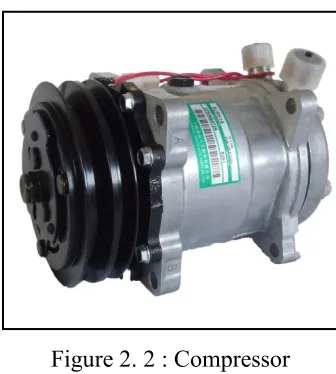
[image:22.612.242.410.273.460.2]2.3.1 Compressor
Figure 2. 2 : Compressor
(Source: http://www.gasgoo.com/showroom/shxinjing/auto-products/1079202.html)
12
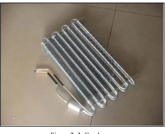
[image:23.612.185.470.129.361.2]2.3.2 Condenser
Figure 2. 3: Condenser
(Source: http://www.ecvv.com/product/2382590.html)
13
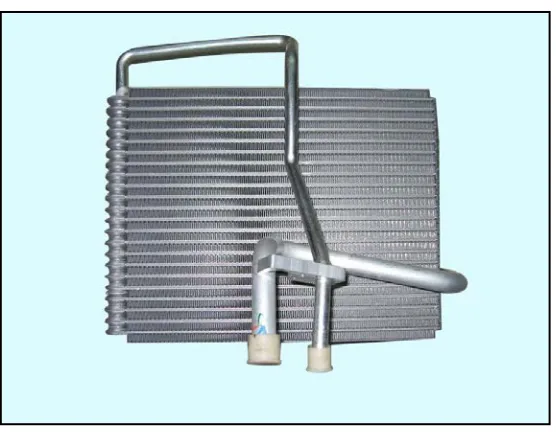
[image:24.612.150.428.128.351.2]2.3.3 Evaporator
Figure 2. 4 : Evaporator
(Source: http://www.elephanttrade.com/ExporterList)