SMART PARKING VIA RFID TAG
AKMARINA IZZA BINTI MOKERI
This Report Is Submitted In Partial Fulfillment Of Requirements For The Bachelor Degree of Electronic Engineering (Industrial Electronic)
Fakulti Kejuruteraan Elektronik dan Kejuruteraan Komputer Universiti Teknikal Malaysia Melaka
iii
“I hereby declare that this report is the result of my own research except for quotes as cited in the references.”
Signature : ………..
iv
“I hereby declare that I have read through this report and in my opinion this report is sufficient in terms of scope and quality for the award of Bachelor of Electronic
Engineering (Electronic Industry) with Honours.”
Signature : ………...
v
vi
ACKNOWLEDGEMENT
The success and accomplishment of this report cannot be achieved without the support, encouragement and helps from others. All praises are due to Allah SWT, the Lord of The World who made it possible for me to complete this project. Blessings and salutations are on the Last Prophet of Allah SWT, Muhammad SAW.
First and foremost, I would like to express my appreciation and gratitude to all parties and those who have been involved in contributing their precious ideas and time in helping me to prepare and complete this project and report. Special thanks to my supervisor, Miss Siti Aisyah binti Anas, for her guidance, advice, encouragement, suggestion and constructive views of this project. I am absolutely grateful for the valuable time that she spends on me.
vii
ABSTRACT
viii
ABSTRAK
ix
TABLE OF CONTENTS
CHAPTER TITLE PAGE
PEOJECT TITLE i
CONFIRMATION REPORT STATUS ii
DECLARATION iii
SUPERVISOR DECLARATION iv
DEDICATION v
ACKNOWLEDGEMENT vi
ABSTRACT vii
ABSTRAK viii
TABLE OF CONTENTS ix
LIST OF TABLES xii
LIST OF FIGURES xiii
LIST OF ABBREVIATIONS xv
LIST OF APPENDICES xvi
1 INTRODUCTION
1.1 Project Overview 1
1.2 Problem Statement 2
1.3 Objective of Project 2
1.4 Scope of Project 3
1.5 Brief Description of Methodology 3
x
2 LITERATURE REVIEW
2.1 Introduction 5
2.2 Parking System 5
2.2.1 PGS using Ultrasonic Detection 6
2.2.2 Wireless Sensor Network 8
2.2.3 RFID Parking Management System 10
3 METHODOLOGY
3.1 Introduction 12
3.2 Project Implementation 12
3.2.1 Hardware Design 14
3.2.2 Software Design 22
3.2.3 Hardware and Software Integration 26
3.3 Method of System 26
3.4 Project Schedule 28
4 RESULT AND DISCUSSION
4.1 Introduction 29
4.2 Project Result 29
4.2.1 Hardware Development 29
4.2.2 Software Development 39
4.2.3 Prototype 53
4.3 Discussion 54
5 CONCLUSION AND RECOMMENDATION
xi
5.2 Conclusion 56
5.3 Recommendation 57
REFERENCES 58
APPENDIX A 60
APPENDIX B 61
APPENDIX C 63
APPENDIX D 67
APPENDIX E 69
APPENDIX F 74
APPENDIX G 77
APPENDIX H 78
APPENDIX I 79
xii
LIST OF TABLE
NO TITLE PAGE
3.1 List Component of Project 14
3.2 26-bit Wiegand Format 17
3.3 LED Indicator State 23
4.1 List Component of Main Controller Circuit 31
4.2 List Component of Sub-Controller Circuit 34
xiii
LIST OF FIGURES
NO TITLE PAGE
2.1 How Ultrasonic Sensor Work 5
2.2 The Smart Parking System uses Ultrasonic Detector 6
2.3 PGS Based on Wireless Sensor Network 7
2.4 RFID Parking Management System 9
3.1 Flow Chart of Project Implementation 12
3.2 Flow Chart of Hardware Implementation 13
3.3 RFID tags 15
3.4 RFID Reader 16
3.5 Data Bit Timing Pattern 16
3.6 PIC16F876A pin out 17
3.7 RF Module 18
3.8 PT2262 Pin Out 19
3.9 PT2272 Pin Out 19
3.10 RS232 Cable to USB 20
3.11 IC MAX232 Pin Out 20
3.12 Flow Chart of Software Implementation 22
3.13 Sketch Design of GUI for Parking System 24
3.14 Sketch Design of GUI for Parking Indicator 24
3.15 Flow Chart of the Parking System 26
4.1 Flow Chart of Circuit Development 29
4.2 Main Controller Schematic Circuit 30
4.3 PCB Layout for Main Controller Circuit 32
xiv
4.5 Sub-Controller Schematic Circuit 33
4.6 PCB Layout for Sub-Controller Circuit 35
4.7 Sub-Controller Circuit Board 35
4.8 Parking Indicator Schematic Circuit 36
4.9 PCB Layout for Parking Indicator Circuit 38
4.10 Parking Indicator Circuit Board 38
4.11 Parking Entrance Log In Form 47
4.12 Parking Entrance COM Port Form 48
4.13 Parking Entrance Form 49
4.14 Parking Indicator Log In Form 50
4.15 Parking Indicator COM Port Form 50
4.16 Parking Indicator Form 51
xv
LIST OF ABBREVIATIONS
CCU Central Control Unit
COM Communication
GUI Graphic User Interface
IC Integrated Circuit
ID Identification
LED Light Emitting Diode
PC Personal Computer
PCB Printed Circuit Board
PGS Parking Guidance System
PIC Programmable Integrated Circuit
PIS Parking Information Server
RF Radio Frequency
RX Receiver
RFID Radio Frequency Identification
TX Transmitter
UART Universal Asynchronous Receiver-Transmitter
USB Universal Serial Bus
VB Visual Basic
VMS Variable Messaging System
WSN Wireless Sensor Network
xvi
LIST OF APPENDICES
NO TITLE PAGE
A Project Gantt Chart 60
B C Program for Main Controller System 61
C C Program for Sub-Controller System 63
D C Program for Parking Indicator System 67
E VB Code for Parking Entrance System 69
F VB Code for Parking Indicator System 74
G PIC16F87X Data Sheet 77
H IC PT2262 Data Sheet 78
1
CHAPTER 1
INTRODUCTION
1.1 Project Overview
RFID is a technology that enables wireless data transmission where able to control data through the use of electromagnetic wave. It is currently used in tracking objects in many industries [1] [2].
This project consists of a system that gives the driver a specific parking lot when entering the car park where the driver needs to park their vehicle at the specified parking with the aided of RFID technology. When driver enters the parking entrance, system will identify and generate the vacant parking space for them and once they accept the parking, an RFID tag will be given. The driver only needs to follow the given sign to search for their parking.
2
Moreover, a screen is provided at the entrance or the exit of the mall for the driver to search their car in case they forgot their vehicle location. They only need to scan the RFID tag and the screen will show the location of their vehicle.
1.2 Problem Statement
Most problems about parking that occurs is coming from the shopping mall. During peak hours especially on weekend and holiday where everyone is coming out doing shopping and spend their leisure time, it would be a frustration for them to find an available parking spot. Although most shopping malls provide very large parking bays but this problem still occurs. The driver will keep on turning around at the parking bay to find a vacant parking space and even sometimes they need to compete with others in order to get their own parking spot. Time taken to park their car is high even can take more than 10 minutes [3] and driver had wasted the fuel consumed plus it is not green. Apart from that, drivers also waste their precious time. As a solution, this project is able to reduce the frustration and increase efficiency of driver to find a vacant parking space.
Another problem that occurs is sometimes driver does not remember or forgotten where they had parked their car after they have done with their shopping or their business. It is also a troublesome to find the vehicle if the parking bay is quite large and had multiple level especially when each level look similar. Besides that, to find the forgotten vehicle location will take some times. An indicator is needed to solve this problem.
1.3 Objective of Project
The objectives of this project are as follows:
3
1.4 Scope of Project
In order to achieve the project objectives, the scope of the project is determined as to specify the requirement and function of the project. All the scopes are listed as follows:
(a) Driver can choose the parking lot for themselves. (b) Passive RFID tag is used.
(c) An RFID tag is given when driver confirms the parking lot.
(d) Sweep the RFID reader with RFID tag when entering and leaving the parking lot is required.
(e) Indicator only shows the parking lot for the particular RFID tags.
1.5 Brief Description of Methodology
This project gives a specific parking space to the driver upon entering the parking area with the aided of RFID elements. RFID tag helps the system identify how many vacant parking spaces that available along with helping to indicate the parking location for the drivers. In order to develop this project successfully, the project methodology is divided into three stages which are hardware design, software design, as well as hardware and software integration. The methodology of this project included all of the flow processes are briefly explained in chapter 3 of this report.
1.6 Report Outline
4
5
CHAPTER 2
LITERATURE REVIEW
2.1 Introduction
Nowadays, there are many researchers develop a new parking system using different approach method to solve the current problem having by driver that want to find a vacant parking space. The parking system is being improved day by day to make it more reliable and efficient in regard of solving the problem that still occurs and also the safety of the vehicle.
In this chapter will discuss the literature study of another researcher made that relate to this project.
2.2 Parking System
6
2.2.1 PGS using Ultrasonic Detection
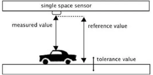
[image:22.595.187.454.302.434.2]A smart parking system is proposed to assist drivers to find a vacant parking space in a shorter time [5]. The approach method used in this system is by using sensor of ultrasonic detection at the parking lot. The ultrasonic sensor is placed over each parking lot to sense the presence of vehicle at the parking lot. The ultrasonic sensor work by transmitting sound wave and this sound wave will reflect back. The time differences taken between transmit and receive signals of the ultrasonic sensor will determine the presence of the vehicle. Figure 2.1 [5] show how ultrasonic sensor is working.
Figure 2.1: How Ultrasonic Sensor Work
7
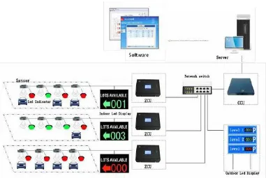
Figure 2.2: Smart Parking System uses Ultrasonic Detector
CCU will process the data that receive from the ZCU and instruct the command to the ZCU and the LED display board to update the parking space information. Apart from receiving data from the ultrasonic sensor, ZCU also receive commands from CCU to control the LED indicator at each parking lot and also the indoor LED display. All the data collected that receive at CCU will be saved on the server and allows the information be monitored and managed by the management.
This system guides the driver to the available vacant parking space by showing the amount of available vacant space on the LED display. The LED display is being placed in several places included the entrance of parking lot, entrance each level and end of each aisle [5]. From the LED indicator which have several colors that indicate either reserved, occupied, vacant or handicap also helps the driver to observe the vacant parking space smoothly.
8
other driver that wants the same vacant parking space. It is still unreliable parking system development and problem still occur with this system implementation.
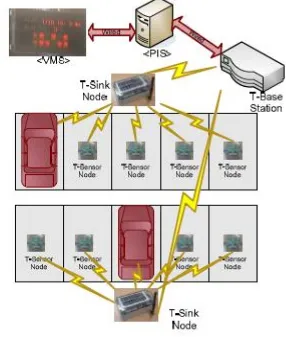
2.2.2 Wireless Sensor Network
[image:24.595.177.463.342.679.2]Wireless sensor network is one of the enabling technologies for such a ubiquitous computing world which expected will be used in all sorts of applications including home security, asset and inventory tracking and etc. [6] [7]. A wireless sensor network is implemented in a parking system to build a systematic parking guidance system which consists WSN based vehicle detection sub-system and management sub-system as shown in Figure 2.2 [8]