“I hereby declare that I have read this thesis and in my opinion this thesis is sufficient in term of scope and quality for the reward of the Bachelor’s degree of
Mechanical Engineering ( Design and Innovation)”
Signature : ………. Name of First Supervisor :………. Date :……….
STUDY ON FRACTURE IN LOW CARBON STEEL USING BEND SPECIMEN WITH AND WITHOUT CARBURIZING
ANNA MARIE ALMODIEL
This Report Is Submitted In Partial Fulfillment Of Requirements For Degree In Bachelor Of Mechanical Engineering (Design and Innovation)
Faculty of Mechanical Engineering University Technical Malaysia Malacca
ii
“I declare that this report is the result of my own effort except for quotations and extracts which is mentioned as reference”
iii
DEDICATION
iv
AKNOWLEDGEMENT
v
ABSTRACT
vi
ABSTRAK
ix
CONTENTS
CHAPTER TOPIC PAGE
DECLARATION ii
DEDICATION iii
ACKNOWLEDGEMENTS iv
ABSTRACT v
ABSTRAK vi
CONTENTS ix
LIST OF TABLE x
LIST OF FIGURE xi
NOMENCLATURE xii
LIST OF APPENDIX xiii
CHAPTER 1 INTODUCTION 1
1.1BACKGROUND OF STUDY 1
1.2PROBLEM STATEMENT 2
1.3OBJECTIVES 2
1.4SCOPE 3
ix
CHAPTER 2 LITERATURE RIVIEW 4
2.1METHOD 4
2.2 TERMINOLOGY 4
2.2.1 FRACTURE 5
2.2.1.1 FRACTURE TOUGHNESS 5
2.2.1.2 NOTCH 10
2.2.2 LOW CARBON STEEL 10
2.2.3 THREE POINT BENDING 12
2.2.4 CARBURIZING 14
2.2.5 FLEXURAL TEST 17
CHAPTER 3 METHODOLOGY 19
3.1 METHOD 19
3.2 SPECIMEN PREPARATION 21
3.3 CARBURIZING PROCESS 26
3.4 FLEXURAL TEST 29
3.5 FATIGUE PRE-CRACKING 31
3.6 FRACTURE TOUGHNESS TEST 31
CHAPTER 4 RESULTS 36
4.1 FLEXURAL TEST 36
4.2 FATIGUE PRE-CRACK 39
4.3 FRACTURE TOUGHNESS TEST 42
CHAPTER 5 DISCUSSION 46
5.1 FRACTURE 46
ix 5.3FACTORS AFFECTING
FLEXURAL TEST, PRECRACKING
AND FRACTURE TOUGHNESS TEST 49
5.4 KEY FACTORS IN PEFORMING THREE POINT BEND TEST 51
CHAPTER 6 CONCLUSION AND RECOMMENDATION 52
REFERENCES 54
x
LIST OF TABLE
NUM TITLE PAGE 3.0 Specific Values of Crack Length over Width 34 3.1 Fracture Toughness for Metal 35 4.0 Comparisons for Flexural Load at Yield 38 4.1 Fracture Toughness for Un-Carburized Specimens 45 4.2 Fracture Toughness for Carburized Specimen 45 5.0 Comparison between Un-Carburized
xi
LIST OF FIGURES
NUM TITLE PAGE
2.0 Crack Observation 6
2.1 Fractured Blade of An Aircraft 9
2.2 Notches 10
2.3 Metal of Low Carbon Steel 11
2.4 Three Point Bend Specimen 12
2.5 Model Specimen in Finite Element 13
2.6 Recommended Drawings 13
2.7 Cracks on Three Point Specimens 14
2.8 Metal Undergone Carburizing Processes 15
2.9 Pack Carburizing Process 16
2.10 Stress-Strain Diagram 17
2.11 Three-Point Flex 18
3.0 Methodology Flow Chart 20
3.1 Welding Cylinder 21
3.2 Bend Saw 22
3.3 CNC Milling Machine 22
3.4 Chamfering Machine 23
3.5 Low Carbon Steel Plate 24
3.6 Personnel Wearing PPE 24
3.7 Minor Part of Mild Steel 25
xi
3.9 The Squaring Process 26
3.10 Solid Carburizing 27
3.11 The Cooling Process of The Carburized Specimen 28
3.12 Carburized Specimens (T1) 28
3.13 Placing of Specimen on Apparatus 30
3.14 Specimen Setting 30
3.15 Universal Testing Machine 32
4.0 Flexural Test For Un-Carburized Specimen 36
4.1 Fatigue Parameters for Un-Carburized 37
4.2 Flexural Test for Carburized Specimen 37
4.3 Fatigue Parameters for Carburized 38
4.4 Un-Carburized Specimen 2A 39
4.5 Specimen 2A Pre-crack 39
4.6 Un-Carburized Specimen 2B 40
4.7 Un-Carburized Specimen 2B Pre-Crack for 40
4.8 Graph Load versus Cycle for Fatigue Pre-Cracking for Un-Carburized Specimen 41
4.9 Graph Load versus Cycle for Fatigue Pre-cracking for Carburized Specimen 41
4.10 Pre-crack for Carburized Specimen 42
4.11 Fracture Toughness Cracks for Un-Carburized Specimens 43
4.12 Fracture Toughness Cracks for Carburized Specimens 43
5.0 Un-carburized Specimen before Pre-Cracking 47
5.1 Un-Carburized Specimen Microstructure 48
xii
NOMENCLATURE
KQ = Fracture Toughness ( MPa.m1/2)
PQ = Load maximum kN
S = Span in cm B = Base in cm W = Width in cm
w
a = Crack Length over Width
w a
f = Dimension less parameter or function depend on crack and specimen size
K = Stress intensity factor Y = dimensionless factor (1.00)
σ =
Yield Strengthxiii
LIST OF APPENDIX
NUM TITLE PAGE
A Autocad Drawing of Specimen 57
B Theoretical Crack Path Prediction 59
C Bend Test Fixture Design 61
1
CHAPTER 1
INTRODUCTION
1.1BACKGROUND
2
1.2PROBLEM STATEMENT
Studies on the impact of Carburizing towards metal surfaces had mainly focused on properties such as corrosive and wear of metal material such as low carbon steel. In spite of all the emphasizing on corrosion and wear, many have failed to focus on a vital matter such as fracture on metals. Cracks and fracture can occur on any shapes and form of metal such as straight, circle and bended. In fact, fracture is one of the reasons for the failure of technological invention in today’s modern world. Catastrophic failures in major airlines crashes, sunken vessels and explosion of space shuttles are also contributed by fracture of materials (Anderson, 1994). Hence, Fracture mechanics slowly develops with the main intention to do analysis on more sophisticated models of material behavior. In coherent, research on fracture in low carbon steel using with and without carburizing bend specimen is implemented.
1.3OBJECTIVE
The main objective of this project is to investigate fracture behavior and its mechanism in low carbon steel (AISI 1020) using a bend specimen with and without carburizing. Other objectives are:
1) The carburizing method used in this project is solid carburizing where Wilcarbo powder is involved in the surface hardening process and conducted at the temperature of 850°C.
2) Other intentions involved in this final year project are designing experiments and conducting it to Low Carbon steel Specimens. These experiments includes Flexural testing with the purpose if gaining the maximum load that the material can withhold and 3-point bending test which is significant to obtain the fracture toughness.
3
1.4SCOPE
Materials prepared for this investigation are low carbon steel and there are ten specimens all together. These specimens are prepared by using machines such as Bend Saw, CNC milling Machine and EDM Wirecut Machine. Five specimens undergo solid carburizing which is done in a prepared furnace and another five will be left un-carburized. Two specimens are involved in Flexural test which consist of one from Carburized specimen and another as Un-Carburized. Three point bending experiment will be conducted on six out of ten bend specimen by using INSTRON 8802 Digital Control. Another four are set to be back ups in case there are any complications occurred during the testing. Upon completion, specimens are evaluated under microscopes to analyze cracks and grain structure.
1.5OVERVIEW
4
CHAPTER 2
LITERATURE RIVIEW
2.1 METHOD
The method used to obtain information for this final year project is archival collection. Facts, data and information as well as knowledge pertaining study on fracture in low carbon steel (AISI 1020) using bend specimen with and without carburizing were taken from internet, reference books and journals.
2.2 TERMINOLOGY
5
2.2.1 FRACTURE
Fracture is the state of being broken and further meaning is brought from Oxford dictionary where fracture is an instance of braking or being broken. According to Broberg K. Bertam (1999), “A crack may be defined as a material separation by opening or sliding, with the separation distance substantially smaller than the separation extent-the crack length”. Fracture however, thought as an event where increased loading abruptly causes accelerated growth of pre-existing cracks. The fracture properties are discussed on the basis of crack initiation and small crack growth behavior and fracture surface analysis. William F. Smith (2003) mentioned in his study that the fracture of a metal starts at a place where the stress concentration is the highest, which may be at the top of a sharp crack. Thus, specimens in this project are having purposely initiated cracked in order to obtain precise and explicit results.
2.2.1.1 FRACTURE TOUGHNESS
The resistance to fracture of a material is known as its fracture toughness (Pisarski, 2004). The facture toughness of a material usually depends on the orientation and direction of propagation of the crack in relationship to the anisotropy of the material, which depends, in turn on the principal direction of mechanical working of grain flow. The system enables the classification of course of crack plane at any time possible provided that it is still in the system (ASTM, 2004). Fracture surface analysis is carried out using Scanning Electron Microscope (SEM).
6
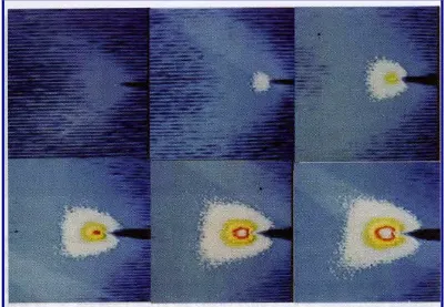
Figure 2.0 Crack Observation (Source: Bui, Ehrlacher and Nguyen, 1979)
Fracture mechanics testing techniques are usually applied on testing of metal material which contains sharp crack in relation to the environment factors. Generally, the testing on Early Age Cracking (EAC) is using constant load or also known as constant deflection specimens. This is a procedure where load used on the material are either directly applied dead weight or by using pulley to increase the dead weight load (Corrosionsource.com, 2002).In the study of Low Carbon Steel using Bend Specimen with and without carburizing on the other hand uses fracture toughness test which is related to the surface hardened material. The test design for this project is the fracture toughness test in order to obtain the fracture toughness of the materials and to observe failure behavior of the materials subjected to the cyclic load.
7 K, can be considered as a stress-based estimate of fracture toughness. It is derived from a function which depends on the applied force at failure. K depends on geometry of the flaw depth, together with a geometric function, which is given in test standards.
CTOD or (crack-tip opening displacement) can be considered as a strain-based estimate of fracture toughness. However, it can be separated into elastic and plastic components. The elastic part of CTOD is derived from the stress intensity factor, K. In some standards, the plastic component of CTOD is obtained by assuming that the specimen rotates about a plastic hinge. The plastic component is derived from the crack mouth opening displacement (measured using a clip gauge). The position of the plastic hinge is given in test standards for each specimen type. Alternative methods exist for estimating CTOD, which make no assumption regarding the position of the plastic hinge. These require the determination of J from which CTOD is derived. CTOD values determined from formulations assuming a plastic hinge [may differ from those determined from J.
J (the J-integral) is an energy-based estimate of fracture toughness. It can be separated into elastic and plastic components. As with CTOD, the elastic component is based on K, while the plastic component is derived from the plastic area under the force-displacement curve (Pisarski, 2004).
Another approach to evaluate fracture is through linear elastic fracture mechanics (LEFM) where the stress intensity factor, Kl describes the elastic crack
tips stress field when a material is loaded perpendicular to a crack plane. The stress intensity at the tip of the crack can be calculated using standard equations as given in the book of guideline, ASTM (2004) which states Kl= Yσ (πа)1/2. In order to analyze the relationship between crack growths rate versus stress intensity Kl, dead
weight-loaded specimen are used and the experiment will emphasize on the crack length. As the force increases, the crack will grow and as it reached the critical length, fast fracture will occur and it is vital that the load at fracture to be identified. The resistance of this material to fracture may be characterized by the stress intensity at fracture, KlC, which is also known as the fracture toughness. Fracture to occur when
8 Fracture toughness of a material and the manner in which the crack grows depends on strength and thickness of the specimen. For thickness independent fracture toughness, the linear elastic fracture mechanics is applied. There are many types of fracture toughness testing that includes Testing of Compact Specimens, Testing of The Arc-Shaped Tension Specimen and the Testing of Disk- Shaped Specimen. This project implements the Testing of Bend Specimen.
For the Testing of Compact Specimens, the standard compact specimen is a single edge-notched and fatigue cracked plate loaded in tension. There are two holes at both sides of the notch which will be used for clevis and also to be loaded through pins. The size of these holes depends on the critical tolerances and suggested proportions (ASTM, 2004)
Besides Testing of Compact Specimens, there is also Testing of The Arc-Shaped Tension Specimen. It has a single edge-notched and fatigue cracked ring segment loaded in tension. This type of fracture testing intends to measure the fracture toughness so that the normal to the crack plane is the circumferential direction and the direction of the crack propagation is in the radial direction. The inner radius and outer radius, r1 and r2 are usually not specified to enable the
preparation of the arc specimen from any cylindrical geometry.
Testing of Disk-Shaped Specimen is one of types in fracture toughness testing provided that the specimen shape is a disk. The standard Disk-Shaped compact Specimen is a single edge-notched and fatigue cracks disk segment loaded in tension.
For this final year project, the test implemented is the Testing of Bend Specimen. The Standard bend specimen is a single edge-notched and fatigue cracked beam loaded in three-point bending with a support span, S, nominally equal to four times the width, W.
9
KQ =
( )
w a f W B S P . . . 2 3
The value of w a
f are specified in the table provided by ASTM Standard guide book and the table varies according to each type of fracture toughness testing.
[image:24.595.149.495.68.190.2]Complications that might occur during this experiment is the crack growth tend to increase along with the value of K as the crack proceeds and thus, crack opening displacement has to be at a rapid rate. Sometimes the period required to run a decreasing K test is very longand to avoid such issue is to use a rising load test whereby the fracture mechanics specimen is subjected to an increasing load provided that the crack open displacement is monitored.
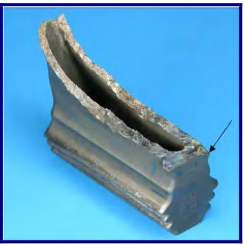
Figure 2.1 Fractured Blade of an Aircraft (Source: Australian Transport Safety Bureau, 2006)
[image:24.595.200.440.362.602.2]