1
Open type ferry safety systems design for using LNG fuel
D.-N. Pagonis
1*, G. Livanos
1, G. Theotokatos
2, S.Peppa
1N. Themelis
31. Department of Naval Architecture, Technological Educational Institute of Athens, Greece 2. Department of Naval Architecture, Ocean and Marine Engineering, University of Strathclyde,UK 3. Hellenic Register of Shipping, Greece
*Corresponding author Email:
Abstract
This feasibility study investigates the viability of employing Liquefied Natural Gas (LNG) fuel to an open type Ro-Ro passenger ferry and the potential challenges imposed with regard to the vessel safety systems. The study proposes appropriate methodology for converting the existing ship to run on LNG fuel and discusses all the necessary modifications to the ship’s safety systems; furthermore, the ship’s evacuation analysis is investigated accordingly. The basic requirements that the ship already complies with are initially reported for each safety system while the additional restrictions that need to be taken into consideration for employing LNG fuel are analysed; appropriate actions are proposed. Furthermore, a Hazard Identification Study (HAZID) is also carried out. Overall, the technical feasibility of the investigated scenario is clearly demonstrated; minimal modifications to the ship's safety systems in order to comply with the imposed safety rules are required for the specific type of ship.
Keywords
LNG fuel; Fuel conversion; Ship safety systems; LNG regulations; Open-type ferry; Design study;
1. Introduction
2
In this paper, we have performed a detailed study of converting an open type Ro-Ro passenger ferry to employ LNG fuel -with respect to its safety systems; the investigation involves the analysis of all the necessary modifications and the proposal for appropriate actions. In particular, the additional requirements for the ship safety systems to run on LNG are considered and the necessary modifications are determined; the study is based on the regulations required at national and international level for the operation of ships
with LNG fuel (HRS rules http://www.hrs.gr, DNV GL rules https://www.dnvgl.com). It should be noted
that to the knowledge of the authors there are no available studies investigating the retrofitting of an existing Ro-Ro passenger ferry with regard to the vessel safety systems.
The modifications under evaluation cover all ship’s safety systems and are divided into four main categories including Fire Safety systems, Ventilation system, Fire and Gas detecting safety measures and Evacuation of the ship. Furthermore, a quantitative Hazard Identification Study (HAZID) has been performed based on an expert’s panel for an open type ferry.
2. Methodology
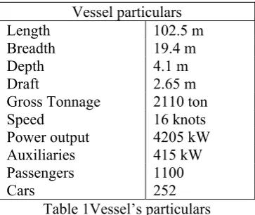
As already mentioned the present study evaluates the technical feasibility of retrofitting a typical existing open type Ro-Ro passenger ferry in order to operate on liquefied natural gas (LNG). The particulars of the vessel are presented in the table below (Table 1). We should note that the selection of the specific type of vessel is mainly based on the wide usage of similarly designed vessels operating on domestic coastal routes throughout the Greek territory, and especially close to urban areas; thus, employing LNG as fuel for the particular type of vessel is of great interest and importance.
Vessel particulars
Length 102.5 m
Breadth 19.4 m
Depth 4.1 m
Draft 2.65 m
Gross Tonnage 2110 ton
Speed 16 knots
Power output 4205 kW
Auxiliaries 415 kW
[image:2.595.200.382.379.532.2]Passengers 1100 Cars 252
Table 1Vessel’s particulars
The study was focused on the analysis of the following:
• Fire Safety systems: modifications on the ship safety systems required for the storage and use of
liquefied natural gas as fuel for ships, taking into consideration the additional requirements for the ship safety systems and the regulations required at national and international level for the operation of ships with fuel LNG. In particular, the required alterations to Fire insulation, Fire pumps (number and capacity), Fire line, Water spray systems (Sprinkler/Drencher) and Fixed/Portable fire extinguishing
systems (CO2, etc) are investigated.
• Ventilation system: the topology of the existing system (air inlets/outlets etc), the capacity of the
installed fans, the capacity and the location of the additional fans required for the LNG fuel line are examined.
Fire and Gas detecting safety measures: the addition of an appropriate gas detection system is analysed
and proposed including the system’s type, sensor’s topology and the appropriate interfacing to the ship’s LNG fuel supply automation system.
• Evacuation plan: the number and topology of lifesaving appliances (i.e. number of life jackets, number
3
Hazard Identification Study (HAZID): an identification of main hazards and evaluation of the severity
and the probability of each hazard has been investigated with the participation of local maritime experts and research scientists.
The study will include the
2.1 Modification of the Fire safety systems
As a result of several fire casualties onboard, the fire safety regulations for ships have been improved considerably. The increased need for requirements for fire safety aboard ships was the basis for the development of the current rules and regulations [Regulation 2, 2.1 SOLAS (1974) as amended]. According to previous study concerning the LNG fuel feeding system of the particular ship, two storage tanks are necessary [Theotokatos G et al. (2015)]. The required LNG tanks are located at an appropriate superstructure on top of Platform Deck – as shown at Fig. 2.
In the following sections the fire safety systems of the specific ship will be investigated in order to determine the feasibility of employing LNG as fuel with respect to fire safety and the potential necessary modifications that have to be performed. In particular the following are analysed for the particular case study: Fire insulation, Fire pumps (number and capacity), Fire line, Water spray systems and Fixed/Portable fire extinguishing systems.
2.1.1 Fire insulation
According to SOLAS regulations, ship spare parts are classified with respect to fire insulation in three categories: “A”, “B” and “C” Class Division [Regulations 2, 3, 4, 10 SOLAS (1974)]. The ship is always divided into main vertical zones. Main vertical zones are those sections into which the hull, superstructure and deckhouses are divided by “A” class divisions, the mean length and width of which on any deck does not typically exceed 40 m [Regulation 3, 32 of SOLAS (1974)].
Fig. 1 Side view of the ship’s existing fire insulation
Most of the fire insulation employed on the vessel is of Class A-60 standard (see Fig.1). In particular, the floor of the accommodation deck and certain areas of the Sun Deck are shielded with Class A-15 insulation. The area of the emergency generator and the rest of accommodation spaces are shielded with Class A-60
insulation. Τhe sides of the ship from the main deck to the ceiling of the accommodation space are shielded
with Class A-60 insulation whilst the windows at the accommodation deck are of Class A-0.
4
The docking station and the superstructure where the LNG tanks are located should be shielded with
Class A-60 insulation (the boundaries surrounding the LNG tanks are already shielded with class A-60 insulation, as shown at Fig. 2).
The windows of the accommodation space facing the LNG tanks should be removed and replaced by
appropriate Class A-60 standard insulation sheet.
The bridge windows facing the LNG tanks should be replaced by windows of Class A-0 standard.
The side of the stairways facing tanks on Accomodation Deck should be shielded with Class A-60
insulation.
Fig. 2 Insulation at Platform Deck and at the boundaries of superstructure where the LNG tanks are located
2.1.2 Fixed Fire extinguishing systems
According to HRS rules concerning fixed fire extinguishing types by Mizithras P et al. (2015), every ship shall be equipped with sufficient means to suppress and swiftly extinguish a fire in the space of origin. Usually, the most common fire extinguishing mean is the main fire water supply system, consisted of hydrants and hoses. Beside this, various fixed fire extinguishing systems can be installed on the ship for that purpose, regarding the potential fire growth in protected spaces. In addition, some fixed fire extinguishing appliances can be used, which are usually one of the following types:
Fixed gas fire extinguishing system
Fixed expansion foam fire extinguishing system
Fixed pressure water spraying fire extinguishing system
The ship is equipped with appropriate Fire Sprinkler / Drencher system according to Resolution A.123 (V) of
International Maritime Organization (2012) and CO2 system according to Chapter 2-II, Part A, R.5.1 of
Council Directive 98/18/EC (1998). The main characteristics of each system are presented below. It must be noted that only the key aspects of each system are presented since there is no need to re-evaluate the already approved by the class and flag authorities.
The Sprinkler system consists mainly of a pump with nominal characteristics of 90 m3/h and 5 m head (the
required capacity is 84 m3/h) and a sprinkler tank with a volume of 2800 Lt. The Sprinkler tank together with
the Sprinkler pump is located beside the After Engine room. There are two Sprinkler stations onboard; their specifications are presented in Table 2.
Sprinkler station
Deck Area (m2) Head (m)
1 Accommodation Deck 1012.26 120
2 Wheel house Deck, Sun Deck 169 21
Table 2 Sprinkler system’s specifications
The Drencher system consists of three Drencher pumps with nominal characteristics of 140 m3/h and 30 m
5
Drencher pumps are located in the After Engine room. There are four main Drencher zones onboard; their specifications are presented in Table 3.
Drencher Zone Area (m2)
Height < 2m
Area (m2)
Height > 2m
Deck
ZONE 1 346.5 - Lower Deck
ZONE 2 346.5 - Lower Deck
ZONE 3(A) 213.6 - Main Deck
ZONE 3(B) 163.4 185.436 Platform Deck
TOTAL ZONE 3 377 184.436
ZONE 4(A) 213.6 - Main Deck
ZONE 4(B) 163.4 185,436 Platform Deck
TOTAL ZONE 4 377 184.436
Table 3 Drencher system’s specifications
The ship fixed fire extinguishing system consists of five main CO2 cylinders located in the CO2 room at the
fore side of the Platform Deck next to the stores room. The necessary CO2 capacity is directly proportional
to the volume of each engine room according to Chapter 2-II, Part A, R.5.2 of Council Directive 98/18/EC
(1998). For a total engine room volume of 288 m3 the required quantity of CO
2 is calculated equal to 206 Kg.
Therefore the quantity of five 45 Kg each CO2 cylinder installed in each engine room is considered
sufficient.
Taking into consideration the available additional rules concerning the use of LNG as fuel [HRS rules, Mizithras P et al. (2015), GL Guidelines for the use of gas as fuel for ships, Germanischer Lloyd (2010)], it can be concluded that the existing fixed fire extinguishing systems of the ship (i.e. Sprinkler/ Drencher and
CO2 systems) are sufficient. This is because both the engine rooms of the ship are considered of Inherently
Safe type (all gas fuel piping is of double wall type) and there is no bunkering station on board. Thus, no alteration is necessary at the specific systems. We should note though that a fixed water spray line for the LNG fuel tanks is necessary to be installed (see section A2 of Appendix) as presented in the next section.
Water spray system for Gas storage tanks
In the specific case study, the required water spray system for cooling and fire prevention of the exposed parts of gas storage tanks is incorporated into the cassette type LNG tanks. The necessary potential modifications with respect to the ship’s fire pumps (i.e. number/capacity) should be determined in order to provide the additional water supply along with the necessary modifications at the ship’s fire line.
According to the international safety rules imposed by R4 of Council Directive 98/18/EC (1998) every ship shall be provided with appropriate fire pumps, fire mains, hydrants, hoses and nozzles. Ships certified to
carry more than 500 passengers, (ship case) should have at least three fire pumps, one of which may be a
main engine driven pump.
Although there is no additional requirements concerning the number of fire pumps when LNG is employed as fuel, calculations are necessary to verify that the capacity of the existing fire pumps is sufficient to deliver
the additional supply for the water spraying system at the LNG tanks. The ship already has four GS/Fire
pumps installed (two at each engine room); each pump nominal characteristics are 37.5 m3/h and 40 m head.
At first, the appropriate dimensions of the bilge line (internal diameter of main line and branch suction lines) are calculated in order to determine the minimum required bilge pump capacity. The required fixed fire
extinguishing capacity, QFFE is then obtained since it is proportional to the particular figure. Thus, we can
determine if the capacity of the fire pumps already fitted on board, Qinstalled is sufficient to cover both systems
(fixed fire extinguishing, QFFE and LNG water spraying, QLNG_WS i.e. Qinstalled≥ QFFE + QLNG_WS).
According R21 of Council Directive 98/18/EC (1998) and HRS rules, Part5, Chapter 9, 5.2 of Hellenic Register of Shipping (2015) the internal diameters of the main bilge line and the branch bilge suction are
6
All the internal diameters of the main bilge lines should be at minimum 102 mm.
All the internal diameters of the branch bilge suctions should be at minimum 57 mm.
Taking into account that the total number of passengers of the ship is more than 500 and the number of bilge
pumps should be at least three, according R21 of Council Directive 98/18/EC (1998).
The minimum bilge pump capacity is calculated equal to 59.23 / according to HRS rules, Part 5,
Chapter 9, 6.3 of Hellenic Register of Shipping (2015).
It should be noted that the ship has four bilge pumps installed, two of them located in each engine room, with
nominal characteristics 70 m3/ h and 30 m head.
The maximum capacity of the fire pumps installed on the ship is calculated below in order to determine potential alterations to the existing pumping system. The diameter of the ship fire line shall be sufficient for the effective distribution of the maximum required discharge from the fire pumps. Each of the required fire pumps (other than any emergency pump required) shall have a capacity not less than 80% of the total
required capacity divided by the minimum number of required fire pumps, but in any case not less than 25
m3/h according to CHAPTER II-2, R4, 2 of Council Directive 98/18/EC (1998).
The calculated minimum capacity for each pump according to the above rules is equal to . -higher
than the required for the particular ship type. Note that according to the corresponding regulations, for the
specific ship type, three fire pumps are required as a minimum; in the particular ship though four fire pumps
are already installed. The calculated capacity both for bilge and fire pumps are presented in Table 4. Note that the calculated capacity of the fire pump is significantly lower than the installed fire pumping capacity.
Installed Calculated Difference
Fire pump 37.5 m3/h 29.61 m3/h ~ 8 m3/h
Bilge pump 70 m3/h 59.23 m3/h ~ 10 m3/h
Table 4: Installed and calculated capacities of fire and bilge pumps
As mentioned previously, the LNG water spray system should have an application rate of 10 Lt/min/m2 for
horizontal projected surfaces; the total surface of the area, occupied by the two LNG tanks is equal to
59.5 m2. Thus, the additional flow rate necessary to cover the requirements for cooling the LNG tanks in an
emergency situation is calculated equal to . / .
Note that the specific figure is comparable to the minimum required capacity for each of the fire pump
onboard; furthermore, the total pumping capacity required in order to fulfill both requirements (i.e. LNG
water spray system, QLNG_WS plus the minimum fixed fire extinguishing capacity for the particular ship type,
QFFE ) is equal to 29.61 + 35.7 m3/h = 65.32 m3/h, which is almost twice the capacity of each of the fire
pump.
As noticed above, the ship is equipped with an additional fire pump; therefore, one possible solution is to dedicate this pump to the LNG water spray system; thus there would be three fire pumps -to comply with class requirement and one pump dedicated to the LNG water spray system. However, in order for this
scenario to be feasible the total hydraulic loss (taking into account the existing fire line and also the LNG
water spray system line) should be less than 40 m (head of each fire pump); in the following section, this is
verified.
Calculation of hydraulic loss for the existing fire line
The hydraulic loss for the existing fire line is calculated in order to determine if the necessary supply rate can be provided by a single fire pump. Note that the path for each branch of the fire line (for the horizontal hydraulic loss calculations) is considered the longest one at each deck (a typical path is presented in Fig. 3).
The hydraulic loss, HLoss in meters, of each of the line braches is calculated by the following equation
considering the friction loss and the fitting loss (elbows, valves, etc):
(1)
where λ = friction factor
Lp = the length of the fire line branch
din = the inner diameter of the pipe
7
W = the velocity of the fluid
g=9.81 m/sec2.
The friction factor, λ can be easily obtained by Moody chart as a function of the Reynolds number, Re and
the relative roughness, ε/din of the pipe for laminar or turbulent flow. For the surface roughness, ε of the
piping material a representative value of 0.15 for galvanized iron roughness is employed.
The head loss of the fire line branches on the Lower Deck, Main Deck, Platform Deck, Accommodation and
Sun Deck are presented in Table 5 together with the total hydraulic loss which is equal to 20.56 m.
The elevation corresponding to the length of vertical piping is equal to 13.4 m. Furthermore, the minimum water jet height at the last nozzle (at the Sun Deck) is considered equal to 2.1 m (requirement imposed by Chapter II, R4 of Council Directive 98/18/EC (1998)). Thus the minimum head increase of each pump is
equal to 36.06 m which is less than 40 m (head of each pump installed on board).
Location dout(mm) s(mm) din(mm) ε/din Re·105 λ Lp
(m) ζ W(m/s) HLoss(m) Lower-Deck 88.9 4.5 80.9 0.0019 1.2 0.025 20.3 12.3 2.08 3.72 Main-Deck 76.1 3.6 68.9 0.0022 1.36 0.0255 4.06 3 2.77 1.74 Platform Deck 76.1 3.6 68.9 0.0022 1.36 0.0255 48.14 5.1 2.77 8.8 Accomodation
Deck 53.1 0.0033 1.5 0.026 5.22 3.3 3.98 4.66
Sun Deck 53.1 0.0028 1.55 0.026 1.74 1.2 3.98 1.64
Total 20.56
Table 5Head loss calculation for the existing fire line
Calculation of hydraulic loss for the LNG water spray line
To calculate the hydraulic loss for the water spray system due to the LNG implementation, it is assumed that the path line for the water spray system will be identical to the fire main line until the Platform Deck where the line is connected to the LNG tanks water spraying system (as shown at Fig. 4). The corresponding head loss for the water spray line for the Platform Deck is presented in Table 6.
Location dout(mm) s(mm) din(mm) ε/din Re·105 λ Lp
(m) ζ W(m/s) HLoss(m) Platform Deck 76.1 3.6 68.9 0.0022 1.36 0.0255 19.14 3.0 2.77 3.88
Table 6 Head loss calculation for the water spray line at Platform Deck
The total hydraulic loss for the particular line is the sum of the losses on Lower Deck, the Main Deck (decks underneath –as shown at Table 5) and the loss calculated in Table 6. Thus, the total head loss is equal to
9.34 m.
The elevation corresponding to the length of vertical piping is equal to 14.5 m. Thus the minimum head
increase of the pump dedicated to the LNG water spraying line should be equal to 23.84 m which is less than
than 40 m (head of each pump installed on board). As a result, the head of one fire pump is considered sufficient.
As it can been seen from the above calculations the proposed alteration on the vessel fire line is feasible. Note that a connection to the ship fire line through a screw-down non-return valve should be provided in order to comply with the additional requirements for fixed fire extinguishing system, when LNG is used as fuel.
8
Fig. 3 Lower Deck: Path line of the fire system (see line in magenta color)
Fig. 4 Platform Deck: Path line of the water spray system to the LNG tanks (see line in red color)
2.1.3 Portable Fire extinguishers
Apart from the installed fixed fire extinguishing systems, the ship shall be provided with portable fire extinguishers according to Chapter 2-II, Part A, R.6 5.1-5.6 of Council Directive 98/18/EC (1998). According to GL Guidelines for the use of gas as fuel and HRS rules concerning preventive measures, fire
extinction by Mizithras P et al. (2015), one portable dry powder fire extinguisher of at least 5 kg capacity
should be located near the bunkering station. We should note that the above requirement is the only
additional requirement concerning portable fire extinguishers when LNG is employed as fuel.
According to the ship Fire Control Plan, there are 57 portable fire extinguishers onboard described as follows:
20 air-foam fire extinguishers of 10 Lt capacity
31 dry powder fire extinguishers of 6 kg capacity and 2 dry powder fire extinguishers of 12 kg
capacity
4 CO2 fire extinguishers
The above fire extinguishers are located at the ship decks as shown in Table 7 and 8.
Table 7 Lower Deck: Portable fire extinguishers
Portable fire extinguishers (Lower Deck - Deck 1) Extinguisher type After Engine
Room
Fore Engine Room
Machinery
Spaces Garage (693m2)
Dry powder fire extinguisher of
12 kg
1 1 - -
Dry powder fire extinguisher of
6 kg
1 1 2 -
Air-foam fire
9
Table 8 Decks 2 to 6: Portable fire extinguishers
There is no available bunkering station onboard the ship but there is a docking station located on top of the superstructure (since the two LNG tanks are of cassette type). Therefore, two additional dry powder
extinguishers should be added at the specific area. In more detail, twodry powder fire extinguishers of 6 kg
should be added near the docking station as an additional safety measure as shown at Fig. 5.
Fig. 5 Superstructure on top of which the two cassette type LNG tanks will be located
2.2 Modification of the Ventilation System
In the current section, the ship initial ventilation system will be examined in order to detect any potential modifications to comply with the additional rules when LNG is employed as fuel. The basic HRS’s requirements for ship’s ventilation system, are found in the technical report of Mizithras P et al. (2015) - section concerning ventilation system provisions. Taking into consideration the additional requirements (see A3 in Appendix) for employing LNG as fuel, the potential modifications will be determined and appropriate action will be proposed accordingly. Potential modifications/alterations are mainly focused on the system topology (i.e. air inlets/outlets etc), the capacity of the existing fans to supply with air the engine rooms and
the installation of additional fans to preserve the air changes inside the fuel-gaspipingsystems.
It can be safely assumed that the existing ship ventilation system complies with its class/flag requirements. Furthermore, running on LNG, the adequacy of the existing ventilation system to provide with the required air changes the two engine rooms should be examined.
Air changes calculation in machinery spaces:
The following calculation for the machinery spaces are according to ship’s ventilation plan: Machinery space “A”:
Portable fire extinguishers (Decks 2 -6) Extinguisher
type
Main Deck (Deck 2)
Platform Deck (Deck 3)
Lounge Deck (Deck 4)
Sun Deck (Deck 5)
Wheel House Deck (Deck 6)
CO2 - - - 1 1
Dry powder fire extinguisher of
6 kg
16 2 7 2 -
Air-foam fire
10
The capacity of the ventilation system of the machinery space is: 29,000 m3/h
The required air supply for the main engines is: 12,384 m3/h
The required air supply for the generators is: 1,104 m3/h
The remaining capacity of air supply in the machinery space is equal to 15,512 m3/h.
For a machinery space volume equal to 286.32 m3, the air changes are calculated equal to 54.18 air
changes/hour.
Machinery space “B”:
The capacity of the ventilation system of the machinery space is: 29,000 m3/h
The required air supply for the main engines is: 12,384 m3/h
There are no generators at this machinery space
The remaining capacity of air supply in the machinery space is equal to 16,616 m3/h.
The air changes in Machinery space B are easily calculated equal to 58.03 air changes/hour.
We should note that according to the vessel’s approved ventilation plan, both machinery spaces are equipped with one appropriate fan. The ventilation ducts come out from the main deck, underneath the lateral ramps.
Ventilation system for the Machinery spaces
According to previous study concerning the LNG fuel feeding system of the particular ship, all LNG fuel supply lines are of double wall type and both machinery spaces are considered as Inherently Safe type [Theotokatos G et al. (2015)]. Thus, the already installed ventilation system concerning the machinery spaces does not require any change in principle. It should be noted though that there will be an extra load to the installed system due to the necessary air changes inside the double wall fuel supply lines; thus, the system’s adequacy with regard to the necessary air supply in the machinery spaces should be investigated.
Ventilation system of the Double wall fuel supply lines
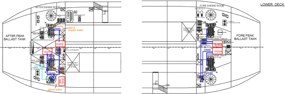
According to the above requirements, a separate ventilation system should be installed on board for the ventilation of the double wall fuel lines. We should note that the system outlets should be located in open air, away from any ignition sources while its capacity shall be at least 30 air changes per hour. Since the four gas valve units (GVUs) are located inside the machinery rooms [Theotokatos G et al. (2015)] they are considered part of the double wall fuel line (Fig. 6); thus, the ventilation capacity for these units should also be equal to at least 30 air changes per hour.
[image:10.595.63.526.475.628.2]
Fig. 6 Double wall fuel line topology inside each machinery room- 4 GVUs are present
The air suction for the ventilation of double wall piping system, will be located inside each machinery room at the point where the fuel supply pipe terminates at each engine; as the gas valve unit is considered part of the double duct in the engine room, the air enters through the gap of the double wall pipe towards the GVU (see Fig. 7).
11
fan should provide the total necessary air supply for the ventilation of the entire double wall piping (serving both machinery spaces).
It should be noted that the fans should not be powered by a common circuit from the main switchboard. Furthermore, it is proposed (although not required) one of the fans to be powered by the emergency power supply; thus, once there is a loss of main power onboard, there is sufficient ventilation provided from the remaining fan in operation.
[image:11.595.133.445.152.292.2]Fig. 7 Air inlet of double wall piping ventilation located at each engine [Jacobs P (2012)].
The ventilation system should always be in operation when gas fuel is in the double wall pipes and it should start and stop before gas is fed into the pipes. Accordingly, the gas will be fed into the inner pipe after the stabilization of the air changes in the double wall pipe (otherwise, for safety reasons the main gas valve will shut down). Complying with the class requirements, the materials, the construction process, the strength of the pipes and ducts of the ventilation system should be resistant to explosions and expansions of the ducts in case of duct breakdown.
Fig. 8 Installation of the two dual wall piping ventilation fans (Vent.1&2) on top of the superstructure where the LNG storage tanks are located-the necessary safety distance requirements are fulfilled.
Calculation of the necessary air supply for the ventilation of the double wall fuel line
The calculations for the air supply required for the ventilation of the gap inside the double wall pipes is summarised in Table 9.
[image:11.595.107.443.456.630.2]12
to GVU1 to GVU2 to GVU3 to GVU4 Units
Diameter-NG pipe
(dinner) 80 80 80 80 mm
Wall thickness 10 10 10 10 mm
Interbarrier
distance 30 30 30 30 mm
Diameter-outer
pipe (douter) 120 120 120 120 mm
Pipeline length (L) 24 24 96 96 m
Interbarrier area 4945.5 4945.5 4945.5 4945.5 mm2
Interbarrier
volume 0.1187 0.1187 0.1187 0.1187 m3
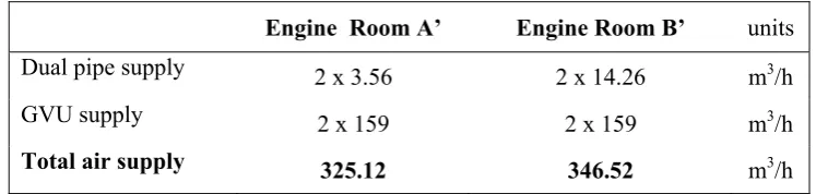
[image:12.595.93.489.69.318.2]Air supply (Qline) 3.56 3.56 14.26 14.26 m3/h
Table 9 Air supply calculation concerning the dual wall fuel lines
Note that the air supply required for the ventilation of the gas valve units-GVUs (there are two GVUs at each engine room) shall be added to the above values.
Typical dimensions of a GVU are 2.3 x 1.9 x 1.2 m3 given in technical report of Pagonis D.- Dimitrellou S.
(2014), which correspond to a volume of approximately 5.3 m3.
By considering 30 air changes per hour, the necessary air supply for each GVU is equal to 159 m3/h; table 10
presents the required total air supply for the two engine rooms.
Εngine Room A’ Engine Room B’ units
Dual pipe supply 2 x 3.56 2 x 14.26 m3/h
GVU supply 2 x 159 2 x 159 m3/h
Total air supply 325.12 346.52 m3/h
Table 10 Total air supply needed for both engine rooms
Thus, the minimum total air supply for each ventilation fan is equal to Qmin = 672 m3/h.
Adequacy of the existing ventilation system for the machinery spaces
Although the additional air supply required for the new ventilation system of the LNG fuel line is relatively small, it should be verified that the existing engine room ventilation system is sufficient, as the inlets of the new ventilation network will be located inside each machinery space.
Machinery space “A”:
The initial remaining capacity of air supply to the machinery space taking into consideration the
engines and gen-sets air consumption is equal to 15,512 m3/h (see previous section -Existing
ventilation system in machinery spaces)
The air supply required for the ventilation of the dual pipe and GVUs is equal to 325.12m3/h
The volume of the machinery space is 286.32 m3
Thus, the new value for the air changes is equal to: (15,512-286.32) m3/h / 286.32 m3 = 53.04 > 30, which is
sufficient.
[image:12.595.103.477.459.548.2]13
The initial remaining capacity of air supply to the machinery space taking into consideration the
engines’ air consumption is equal to 16,616 m3/h (see previous section - Existing ventilation system
in ship’s machinery spaces)
The required air supply for the ventilation of the dual pipe and GVUs is equal to 346.52m3/h
The volume of the machinery space is 286.32 m3
Thus, the new value for the air changes is equal to: (16,612-346.52) m3/h / 286.32 m3 = 56.82 > 30, which is
sufficient. Therefore, we can safely conclude that the capacity of the existing ventilation system of the machinery space is sufficient.
2.3 Modification of the Fire and Gas detecting safety measures
In this section, the existing ship safety measures concerning fire and gas detection, will be examined in order to detect any necessary modifications to comply with the additional rules when LNG is employed as fuel. Taking into consideration that the ship already complies with its class requirements concerning safety measures the necessary modifications to fulfill the additional requirements (see A4 in Appendix) when LNG fuel is employed will be determined and appropriate action will be proposed accordingly. The main modification/alteration in the specific section is focused on the installation of appropriate gas detection system to cover particular areas of the ship.
The ship fire detection system is in compliance with the requirements in CHAPTER II-2-R13 of Council Directive 98/18/EC (1998) [Mizithras P et al. (2015)]. The ship is equipped with a stand-alone fire detection system which currently incorporates 40 smoke detectors and 4 heat detectors; in detail the location of the detectors is as follows:
4 heat detectors are located at the engine rooms (Lower Deck)
7 smoke detectors at the Lower Deck
2 smoke detectors at the Main Deck
16 smoke detectors at the Lounge Deck
15 smoke detectors at the Sun Deck
According to the additional requirements concerning detecting safety measures when LNG is employed as fuel, the necessary alterations are focused on the topology of the existing fire system, the application of heat detectors instead of smoke detectors and the installation of gas detectors at certain areas of the ship. In particular:
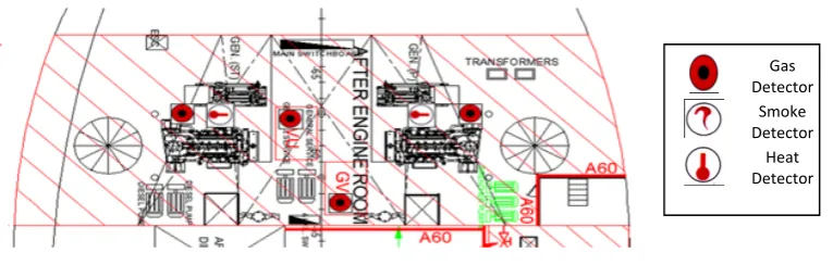
Lower Deck
At the Lower Deck four heat detectors are already installed at the engine rooms (2 in each engine room). According to the additional requirements that should be employed, each engine room is considered an enclosed space containing gas piping whilst each gas valve unit is considered part of the double duct in the
engine room. Thus, it is proposed the installation of eightgas detectors in total, four at each engine room (as
shown at Fig. 9) -two for the engine room space and two for each GVU.
[image:13.595.148.531.619.741.2]Fig. 9 Aft engine room
Gas
Detector
Smoke
Detector
Heat
14
Lower closed garage
At lower closed garage there are seven smoke detectors already installed. There is no need to install any heat or gas detectors as no pipelines or equipment of natural gas exist at the particular area.
Main Deck
At Main Deck (Deck 2) there are four smoke detectors already installed to cover the four Embarkation areas. The number of existing smoke detectors cannot be considered sufficient for fast fire detection because of the rapid gas diffusion in the area and the reduced smoke production when natural gas is burnt. Furthermore, at least one detector shall be installed in a space which accommodates passengers. Therefore, the replacement
of all smoke detectors by heat detectors and the addition of one gas detector at each of the four embarkation
areas (i.e. fourgasdetectors in total) is proposed.
Note that a gas detector should be fitted as well at each enclosed space containing gas piping, thus a heat
detector and a natural gas detector are proposed to be installed at the two enclosed areas of the main deck
where the gas fuel lines enters to each engine room i.e. twoheat detectors and two gasdetectors in total. At
the Garage area no detector device is required as the garage is an open area and there is natural ventilation.
Platform Deck
At Platform Deck (Deck 3) there are available two embarkation areas as well. Correspondingly, it is
proposed a heat detector and a gas detector to be installed at both areas.
The ventilation inlet for the After engine room is located at a distance less than 6 m from the LNG tanks. Note that the two areas are not in the same deck (the superstructure is not at the Platform Deck level) and there is a height difference of 2.62 m; thus, the total distance between the two points of interest is 5.4 m.
According to the regulations a gas detector should be installed at the specific inlet in order to detect a gas
leak.
Alike, the ventilation inlet for the Fore engine room is set near the double wall fuel supply lines for the
specific engine room; therefore an additional gas detector should be installed at the specific inlet.
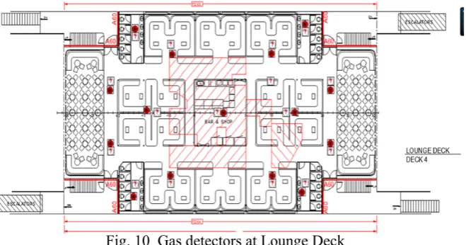
Lounge Deck
The Lounge Deck (Deck 4) is already equipped with appropriate smoke detectors. Although there are no gas pipelines passing through the Deck, gas detectors should be installed due to the relative additional regulations concerning the safety of the passengers. In particular, at least one detector should be installed at
each space where passengers are accommodated. Thus, it is proposed to install eleven gas detectors on the
Lounge main area (in accordance to the maximum spacing of detectors already employed for the existing
smoke detectors) and additionally four gas detectors for the four separate rest-room areas at the deck i.e.
fifteengasdetectors in total (Fig. 10).
[image:14.595.131.461.537.710.2]
Fig. 10 Gas detectors at Lounge Deck
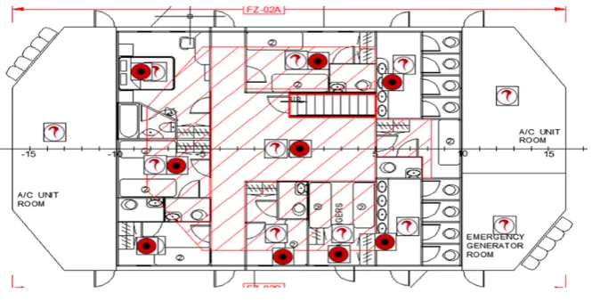
Sun Deck-Wheel House Deck
15
crew is present /accommodated have been fitted with appropriate gas detectors as well. This is proposed taking into consideration the additional requirement for the positioning of gas detectors in areas where
personnel may be present. Therefore, nine gas detectors for the nine separate areas on Sun Deck (Fig. 11)
and one gas detector for the Wheel House Deck should be installed.
[image:15.595.120.453.131.300.2]
Fig. 11 Gas detectors at Sun Deck
Superstructure where the LNG storage tanks will be located
In addition to the above, a gas detector should also be installed at the superstructure where the storage tanks
will be located. More specifically, the detector should be placed near the evaporator skid at the ventilation outlet of the double wall fuel lines ventilation in order to detect any possible gas leak.
Existing fire detection system aboard
The vessel existing fire detection system is a stand-alone AUTRONICA system of type ΒΧ-10Μ (‘M’ stands
for Marine type as described in Installation and Commissioning Handbook of Fire Alarm Control Panel BX-10, Autronica Fire and Security AS (2015). The BX-10M model can support up to four independent zones (loops). The system fulfills all appropriate regulations concerning the ship category (emergency back-up power supply in the main unit, etc.) while it is approved by Det Norske Veritas (DNV), Lloyd’s Register of Shipping (LR) and the American Bureau of Shipping (ABS).
According to the system technical specifications, each detector zone may include up to 32 detectors or manual call-points. Automatic detectors and manual call points may be combined in the same zone whilst disabling a zone is not deactivating the manual call-points in the zone. Furthermore, automatic detectors can include both smoke detectors and heat detectors. Although detailed technical specifications can be found in the system handbook, a brief introduction to system automation interface is necessary in order to initially evaluate the system’s compatibility to the necessary new safety equipment that will be installed onboard, such as an appropriate gas detection system and to the LNG pack interface.
Alarm control signals of the system
The control panel has two sounder outputs, which are activated in parallel when an alarm is given. The outputs give a 24V DC pulsing voltage on alarm and are monitored for breaks and short circuiting. Maximum load per circuit is 0.63A.
Fire detection control signals of the system
There is one control output signal for each detector zone (loop), one output signal common for all four zones and furthermore one signal for the disabled zones. All signals are supplied as transistor controls (open collectors).
Common Alarm Output (BMA) & Common Fault Output (BMF) control signals
16
plus a break and short circuit monitored power output. The specific output is activated at alarm from any zone and is active until the system has been reset.
The available common fault output is used for fault transfer to an external fire alarm receiving station. The output consists of non monitored potential free relay output, plus a break and short-circuit monitored power output.
Compatibility investigation of system automation interface with LNG fuel supply interface
As already analysed in the design study of ship piping systems and machinery for LNG fuel by Theotokatos G et al. (2015), it is proposed that the ship LNG fuel supply will be provided by appropriate cassette type tanks. Consequently, the compatibility of the existing fire detection system to the LNG supply system should be considered. In order to make an initial but a realistic investigation it is assumed that a typical commercial solution for a cassette type tank will be installed on board for LNG storage; that is the LNGPac™ system of Wärtsilä presented by Bui Y (2015).
Process Control Automation
The operation of the LNGPac™ is largely automated and controlled by a PLC-based control system. The central unit of the control system is the PLC cabinet near the tank connection space, which is located in an environmentally controlled space. All operating procedures / sequences, alarm procedures are part of an appropriate software developed by Wärtsilä.
The PLC cabinet consists of three independent PLCs: one for process control and two for safety valves controlled by solenoids which are placed in safe area near the tank docking station, Yang B (2014).
The fire detection and the gas detection system of the ship should be able to be connected directly to the two
Safety Programmable Logic Circuits (PLC) that are incorporated in the LNGPacTM control unit. This should
not be a problematic task since the existing fire detection unit on board provides sufficient control
signals-relay outputs for fire detection. Similarly, potentially installed fire detectors inside the LNGPacTM system can
be connected to an appropriate fire zone of the existing system.
Installation of a typical Gas Detection System
According to class rules, the existing ship does not incorporate a gas detection system. Therefore, a new system should be installed for the gas leakage detection according to the topology previously proposed incorporating a total number of forty four gas detection sensors.
Two typical (commercially available) stand-alone gas detection systems -which one could consider for the particular study, are Martek type MM2000 and Autronica type OGS 2.1 systems respectively; for details see MM2000TM datasheet by Martek Marine Ltd (2015) and Type OGS 2.1 datasheet of fixed gas detection system by Autronica Fire and Security AS (2015a).
Both systems fulfill all appropriate IMO regulations and classification societies’ rules and regulations. The Lowest Explosion Limit detection range (LEL) for both systems is adjustable (0-100%).
Regarding system compatibility with the LNGPac™ automation and control interface, both systems have output control signals (of relay type) for power failure and common system failure, in addition to a common alarm control signal (relay type as well) for gas detection, as standard features; therefore, they can be easily incorporated to the LNG fuel supply unit.
2.4 Evacuation analysis of the ship
This section analyses the evacuation from the existing passenger ship according to present maritime safety regulations. Evacuations analysis is based on a set of five evacuation scenarios and can be related to actual accident scenarios, covering major hazards as gas leakage and fire.
17
The vessel is classed as class ‘C’ ship in compliance with the Council Directive 98/18/EC (1998). According to the approved Passenger Ship Safety Certificate, she can carry onboard up to:
i) 604 persons in summer (592 passengers + 12 crew) and
ii) 548 persons in winter (536 passengers + 12 crew)
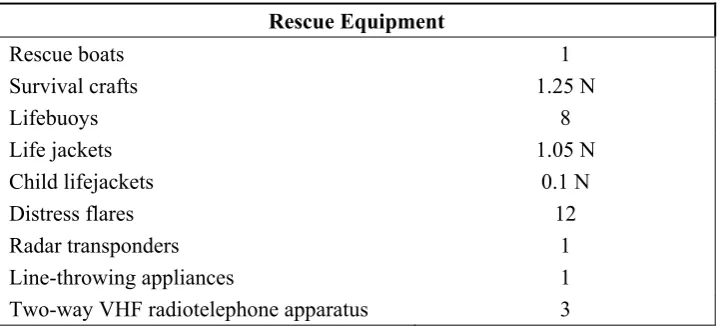
The number of crew onboard is considered equal to twelve according to the existing ship safety plan. Table 11 summarizes the mandatory rescue equipment for the particular ship’s category and number of passengers (i.e. “C” class with more than 250 passengers) -note that N stands for total number of people onboard and is considered equal to 604 which is the maximum number of persons onboard during summer operation.
According to Table 11, the number of survival crafts onboard should be equal to 755 (a safety margin of 25% is taken into account). Thirty one inflatable life rafts, each with a capacity of twenty five persons are
required (755/25 = 31 inflatable life rafts).
At this point, it should be noted that although there are no additional requirements concerning the number of lifesaving appliances (i.e. number of life jackets, number of life rafts etc) with respect to the already existing and fulfilled regulations [Mizithras P et al (2015)], for the case of survival crafts and rescue boats, attention should be paid to their specific location. For this reason, in the following two sections, the main and already fulfilled requirements -concerning the survival crafts of the vessel are presented, whilst the necessary provisions about the location of crafts/rescue boats on a gas fuel ship are included.
Rescue Equipment
Rescue boats 1
Survival crafts 1.25 Ν
Lifebuoys 8
Life jackets 1.05 Ν
Child lifejackets 0.1 Ν
Distress flares 12
Radar transponders 1
Line-throwing appliances 1
[image:17.595.112.474.311.474.2]Two-way VHF radiotelephone apparatus 3
Table 11 Necessary rescue equipment according to Council Directive 98/18/EC (1998) for the particular ship category and number of passengers N (‘C’ class with more than 250 passengers)
With respect to the arrangement and stowage of the crafts onboard the ship complies with the requirements for ro-ro passenger ships according to Chapter III of the Annex to the 1974 Solas Convention, as amended, adopted by Council Directive 98/18/EC (1998).
In accordance to requirements for evacuation in Mizithras P et al. (2015) each survival craft or rescue boat has to be located as follows:
As far as practicable forward of the propeller of the ship. Away from any tank containing explosive or hazardous cargoes. Equally distributed on each side of the ship.
Taking into account the liquefied natural gas storage tanks arrangement.
Furthermore, all the arrangements for installing the required natural gas storage and supply systems shall not reduce the amount or limit the use of life-rafts and of fast rescue boats which are required for the evacuation of the ship.
The existing ship is supplied with twenty four life rafts on wheel house and nine life rafts on the Lounge Deck level, equally distributed –as far as practicable, on both sides of the ship. Furthermore, there is no Davit-launched type life rafts -all are of throw-overboard launching type.
18
According to the above requirements concerning the arrangement and stowage of the crafts onboard the ship,
the survival crafts have to be located as far as practicable forward of the propeller of the ship, equally
distributed on each side of the ship and away from any tank containing explosive or hazardous cargoes. Taking into account that the superstructure where the fuel tanks will be located is near the four crafts at the AFT side of the ship, the specific crafts should be reallocated accordingly. The proposed new location of these crafts is shown in Fig. 12. In more detail, three crafts should be moved to the FOR side of the ship at the same location where a single life raft is already placed; the remaining craft can be moved to the wheel house deck. In this way, there is no life craft near the fuel tanks and their distribution on both sides of the ship is practically equal. Note that the above proposal is feasible since the crafts are not of Davit-launched type.
[image:18.595.91.478.214.371.2]
Fig. 12 Necessary reallocation of life rafts. Four crafts are reallocated from the AFT side (Lounge Deck level) to the FOR side of the ship and to the Wheel house deck in order not to be close to the LNG tanks
2.4.1 Modification to the Evacuation Plan
With respect to the survival crafts, muster stations, embarkation stations and launching arrangements the ship complies with the requirements for Life Saving Appliances in Chapter III of the Annex to the 1974 Solas Convention, as amended, adopted by Council Directive 98/18/EC (1998). According to the additional provisions about gas fuelled ship evacuation plan in Mizithras P et al. (2015) additional requirements (see A5 in Appendix) should be taken into consideration.
With respect to the additional requirements when LNG is used as fuel, a necessary alteration on the ship evacuation plan arises concerning the helicopter pick up area (as shown at Fig. 13). In more detail, although the specific area is not adjacent the LNG fuel tanks, it is proposed to be reallocated from the AFT side of the ship at the Sun deck to the FOR side of the ship at the same deck (as shown at Fig. 13). In this way, at the event of an emergency situation (for any reason) the passengers or the crew will be waiting as far as possible, away from the location of the LNG tanks/equipment.
Fig. 13 Sun Deck: Reallocation of the helicopter pick up area
[image:18.595.54.535.608.715.2]19
In this section, the evacuation analysis is investigated in order to evaluate the existing evacuation plan and identify possible alterations that should be performed when LNG is employed as fuel; such alterations could be the maximum number of passengers onboard during night operation, evacuation paths, etc. The analysis is based on the appropriate Guidelines for evacuation for new and existing passenger ships that apply for the particular vessel type adopted by the MSC.1/Circ.1238 of International Maritime Organization (2007). It should be noted that the presence of the LNG tanks is taken into consideration for the required calculations
for the estimation of the total evacuation time, Ttotal in all the evacuation scenarios considered for the current
study. Furthermore, the worst case of considering an additional number of passengers assembled at the Sun Deck is also evaluated. The five case scenarios considered are described as follows:
Scenario 1: No fire/leakage at the area of the LNG tanks - Summer day operation. Scenario 2: No fire/leakage at the area of the LNG tanks – Summer, operation at night. Scenario 3: Fire/leakage at the area of the LNG tanks – Summer day operation. Scenario 4: Fire/leakage at the area of the LNG tanks – Summer, operation at night.
Scenario 5: Fire/leakage at the area of the LNG tanks – Summer, operation at night assuming additional number of passengers located at the Sun Deck.
Note that summer operation is assumed in all the scenarios since it involves the maximum number of passengers accommodated on board, according to the vessel approved safety certificate (Open type Ferry). The parameters and the methodology involved in the analysis of each case scenario are based on the Guidelines for evacuation for new and existing passenger ships of MSC.1/Circ.1238//30 of IMO (2007) which can be summarized as follows:
Clear width (Wc)
-
Clear width is measured off the handrail (m) for corridors and stairways and the actual passage width of a door in its fully open position. Initial density of persons (d) - The initial density of persons in an escape route is the number of
persons (p) divided by the available escape route area pertinent to the space where the persons are
originally located and expressed in (p/m2).
Specific flow of persons (Fs) - Specific flow (p/(m s)) is the number of escaping persons past a point
in the escape route per unit time per unit of clear width Wc of the route involved. Values of FSare
given in Table 11 as a function of initial density.
Speed of persons (S) - The speed (m/s) of persons along the escape route depends on the specific flow of persons and on the type of escape facility. People speed values are given in Table 12.
Calculated flow of persons (Fc) - The calculated flow of persons (p/s) is the predicted number of
persons passing a particular point in an escape route per unit time. It is obtained from the equation: Fc = Fs · Wc (2) Furthermore:
Flow time (tF) - Flow time (s) is the total time needed for N persons to move past a point in the
evacuation path, calculated as:
tF = N / Fc (3)
where N is the number of persons
Stairway travel time (tstair) – Travel time (s) to traverse a stairway in order to reach the assembly
station.
Deck travel time (tdeck) - Travel time (s) to move from the farthest point of the escape route of a deck
to the corresponding stairway.
Assembly travel time (tassembly) – Travel time (s) to move from the end of the stairway to the entrance
of the assigned assembly station.
Travel time (T) - Travel time expressed in seconds, calculated as:
T = (γ+δ) tI (4)
where: γ is a correction factor to be taken equal to 2 for day operating scenarios and 1.3 for
night operating scenarios
δ is the counter flow correction factor to be taken equal to 0.3,
tI is the sum of travel times (tstair, tdeck & tassembly) expressed in seconds in ideal
conditions
The calculation of total time required for evacuation, Ttotal defined in Guidelines for evacuation analysis for
20 Ttotal = 1.25 (A + T) + 2/3 (E + L) ≤n (5)
where: n= 60 for ro-ro passenger ships,
A is the awareness time and should be 5 min for the day time scenarios, E and L are the embarkation and launching time respectively,
The embarkation and launching time should be calculated separately based upon results of full scale trials on similar ships and evacuation systems or data provided by the manufacturers. For cases where neither of the two above methods apply though, it should be assumed equal to 30 min.
Scenario 1: No fire/leakage at the area of the LNG tanks – Summer, day operation
According to class approved ship evacuation plan, during summer operation, the following distribution of people is considered on board: 284 people located at the Sun Deck plus 536 people at the saloons.
To evacuate the ship, there are four available evacuation paths (at areas A, B, C and D respectively, as shown in Fig. 14) in order to reach the Assembly Stations at the Lounge Deck. Thus, 71 people are assumed to be directed to each evacuation path.
[image:20.595.146.447.259.389.2]
Fig. 14 Sun Deck: Four evacuation paths towards the stairways A, B, C, D are available
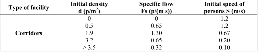
Type of facility Initial density d (p/m2)
Specific flow Fs (p/(ms))
Initial speed of persons S (m/s)
Corridors
0 0 1.2 0.5 0.65 1.2 1.9 1.30 0.67 3.2 0.65 0.20
[image:20.595.67.517.428.519.2]≥ 3.5 0.32 0.10
Table 11 Specific flow of persons, Fs and initial speed, S depending on the initial density, d
As a first the deck travel time tdeck is calculated assuming a minimum speed of persons S equal to 0.67 m/s
according to Table 12 (Corridor type of facility) for all four escape routes on the Sun Deck. We consider the remotest point of the deck towards the nearest stairway. Table 13 summarizes the results; note that the distance from the farthest point of the escape route of the deck to the corresponding stairway has been extracted from the approved plans of the vessel. The value considered is the maximum one (areas A & C).
Type of facility Specific flow Fs (p/(ms))
Speed of persons S (m/s)
Stairs (down)
0 1.0 0.54 1.0
1.1 0.55
Stairs (up)
0 0.8 0.43 0.8 0.88 0.44
Corridors 0 1.2
21
1.3 0.67
Table 12 Speed of persons, S depending on the specific flow, Fs and the type of facility to escape
Sun Deck area Length (m) Speed(m/s) tdeck (s) Comments
A 14.59 0.67 21.78 Value considered
B 12.19 0.67 18.19
C 14.59 0.67 21.78
[image:21.595.62.517.113.225.2]D 12.19 0.67 18.19
Table 13 Deck travel time, tdeck for the A,B, C, D areas on the Sun Deck
The calculation of the stairway travel time, tstairs, (time needed to descent down the stairs to the lower deck)
follows. A minimum speed of persons S equal to 0.55 m/s is assumed according to Table 12 (Stairs –type of facility) for all four escape routes; the corresponding results are summarized in Table 14.
Stairways Length (m) Speed (m/s) tstairs (s) Comments
A 3.8 0.55 6.91 applies for all cases Same travel time
B 3.8 0.55 6.91
C 3.8 0.55 6.91
[image:21.595.68.499.285.566.2]D 3.8 0.55 6.91
Table 14 Stairway travel time tstairs for the four stairways
Fig. 15 Lounge Deck: Assembly travel paths: Four paths are present from the end of each stairway to the entrance of the assigned Assembly station
To estimate the assembly travel time time tassembly we should calculate the travel time to move from the end of
[image:21.595.60.519.691.759.2]each stairway at the Lounge Deck to the entrance of the assigned Assembly station at the same deck (as shown at Fig. 15). A minimum speed of persons S equal to 0.67 m/s is assumed according to Table 12 (Corridor type of facility) for all four routes on Lounge Deck; the corresponding results are summarized in Table 15.
Assembly Path Length (m) Speed (m/s) tassembly (s) Comments
A 8.92 0.67 13.31 Same travel time
applies for all cases
22
C 8.92 0.67 13.31
D 8.92 0.67 13.31
Table 15 Lounge Deck: Assembly travel time tassembly for A, B, C, D paths
In this evacuation scenario the following calculations of flow time are considered: a) using the stairways (from the Sun Deck to the Lounge Deck) and b) using the corridors (entering the Assembly stations at the
Lounge Deck). It should be noted that the value for clear width (Wc ) is extracted from the approved ship
plans whilst the value for the specific flow, Fs depends on the assumed initial density of people which is
considered maximum (worst case). Thus, for a density of 3.5 P/m2 -both for the stairs and the corridors, the
corresponding value for the specific flow, Fs is equal to 0.32 P/(m s) -see Table 11. Furthermore, 71 persons
(N) are considered to be directed to each evacuation path (i.e. to pass through each staircase and corridor) as mentioned previously. The obtained results are summarized in Table 16.
Type of facility FS (P/(m s))
WC (m)
FC = FS·WC (P/s)
tF = N/FC
(s) Comments
Stairways 0.32 1.2 0.384 184.90 Value
considered
[image:22.595.59.523.271.336.2]Corridors 0.32 1.3 0.416 170.67
Table 16 Scenario 1: Calculation of Flow time, Fc for the stairways and the corridors for each of the four
evacuation paths available
As we can see from Table 16, the larger flow time tf is equal to 184.90 s and this is the value considered for
the calculation of the sum of travel times (tstair, tdeck & tassembly) that is equal to 226.89 s.
We can now calculate the travel time T from equation (4), which is equal to 8.70 min. From equation (5) the
total evacuation time, Ttotal for the first case scenario is calculated equal to 37.13 min. We can safely
conclude that the result is acceptable (≤60 min).
Scenario 2: No fire/leakage at the area of the LNG tanks – Summer, operation at night
With this case scenario, we consider different values for the correction factor (γ) and the awareness time (A).
Apart from the appropriate change in these parameters, the analysis is exactly the same as the previous one. Therefore, following the same procedure and assumptions as in the first case scenario we obtained the time to travel and flow time for Scenario 2, as shown in Table 17.
Travel time (s)
Deck travel time (tdeck) 21.78
Stairway travel time (tstairs) 6.91
Assembly travel time (tassembly) 13.31
Flow time (tF) 184.90
[image:22.595.135.427.513.595.2]Sum of travel times (ti) 226.89
Table 17 Scenario 2: Values of Deck/Stair/Assembly travel time and flow time
Consequently for the specific scenario we can use equation (4) and (5) to calculate the travel time T= 8.7 min
and the total evacuation time, Ttotal=43.38 min, respectively. We can safely conclude that the result is
acceptable (≤60 min) in the Scenario 2 as well.
Scenario 3: Fire/Leakage at the area of the LNG tanks – Summer, day operation
To define the third evacuation scenario, a fire/leakage at the LNG fuel tanks is assumed causing possible obstructions or unavailability of some evacuation paths. In particular 284 passengers located at the Sun Deck should only be directed to areas B and D at the FORE side of the vessel (as shown at Fig. 11) since areas A and C at the AFT side of the ship are obstructed due to the fire/leakage at fuel tanks.
Apart from the restriction of the evacuation paths, we should also take into account the increased distance from the farthest point of the escape route of the Sun Deck to the corresponding stairway for the calculation
23
(according to Table 12) as in the previous scenarios for both escape routes; the travel time results of third scenario are summarized in Table 18.
Sun Deck area Length (m) Speed(m/s) tdeck (s) Comments
B 36.52 0.67 54.51 applies for all cases Same travel time
[image:23.595.65.517.125.196.2]D 36.52 0.67 54.51
Table 18 Scenario 3: Deck travel time tdeck - only B and D areas are considered
It should be noted that the Stairway travel time, (tdeck) and the Assembly travel time, (tassembly) are not affected
due to the restriction on the evacuation paths and have the same values as in the previous scenarios; therefore their values are equal to 6.91 s and 13.31 s respectively.
As mentioned above, we use equations (2) and (3) to calculate the flow of persons Fc and flow time tF
respectively. In the specific scenario, 142 persons (2x71) should be considered to be directed to each evacuation path (i.e. to pass through each staircase and corridor) since only two paths are available. Note that
the values for clear width, Wc and specific flow, Fs are not affected and are the same as in the previous
scenarios. The obtained results for Flow time calculations are summarized in Table 19.
Type of facility FS (P/(ms))
WC (m)
FC = FS·WC (P/s)
tF = N/FC
(s) Comments
Stairways 0.32 1.2 0.384 369.80 Value
considered
[image:23.595.55.526.349.418.2]Corridors 0.32 1.3 0.416 341.35
Table 19 Scenario 3: Calculation of Flow time, Fc for the stairways and the corridors – only two evacuation
paths are available
As we can see from Table 19, the higher flow time tf is equal to 369.80 sec and this is the value considered
for the calculation of the sum of travel times tstairs + tdeck + tassembly + tF = 444.53 s. We calculate the travel time
T from equation (4) equal to 17.04 min. From equation (5) the total evacuation time, Ttotal for the Scenario 3
is calculated equal to 47.55 min. We can safely conclude that the result is also acceptable (≤60 min).
Scenario 4: Fire/Leakage at the area of the LNG tanks – Summer, operation at night
For the fourth scenario a Fire or Leakage at the area of the LNG tanks is considered for the night case. The day and night case differ in the awareness time (A) parameter; for the night case, the analysis is exactly the same as the one previously presented (Scenario 3).Thus, following the same procedure and assumptions as in the third scenario we obtained the travel times and flow time in Table 20.
Travel time (s)
Deck travel time (tdeck) 54.51
Stairway travel time (tstairs) 6.91
Assembly travel time (tassembly) 13.31
Flow time (tF) 369.80
Sum of travel times (ti) 444.53
Table 20 Scenario 4: Values of Deck/Stair/Assembly travel time and flow time
As in the above scenarios, we calculate the travel time T from equation (4) equal to 17.04 min. The total
evacuation time, Ttotal for Scenario 4 is calculated from equation (5) equal to 53.80 min. We can safely
[image:23.595.156.417.597.681.2]24
Scenario 5: Fire/Leakage at the area of the LNG tanks – Summer, operation at night assuming additional number of passengers located at the Sun Deck
To further evaluate the safety of the vessel evacuation in case of an emergency, a “worst case” scenario is analysed; a fire/leakage at the fuel tanks area during night operation at summer is considered whilst an additional number of passengers is located at the Sun Deck.
In more detail, it is considered that the passengers assumed at the previous scenario (i.e. 284 in total) are sitting on the available seats while additional passengers are present as well, occupying the available free space on the specific deck.
The free space on the deck - estimated from the available plan, is equal to approximately 28 m2; thus, taking
into consideration a maximum density of people of 3.2 p/m2, we can calculate the number of additional
passengers as 28 m2· 3.5 p/m2 = 98 persons. Thus, a total number of 382 persons is assumed to be located
at the sun Deck.
In order to calculate the Deck, Stairway and Assembly travel time the analysis is exactly the same as the one previously presented assuming a leakage or a fire at the fuel tanks at night (see Scenario 4). Thus, the results for the travel times are presented in Table 21.
Travel time (s)
Deck travel time (tdeck) 54.51
Stairway travel time (tstairs) 6.91
[image:24.595.144.437.276.336.2]Assembly travel time (tassembly) 13.31
Table 21 Scenario 5: Values for Deck/Stair and Assembly travel time
In order to estimate the flow time though, we consider a total of 382 persons located at Sun Deck; the corresponding calculations are presented in Table 22.
Type of facility FS (P/(ms))
WC (m)
FC = FS·WC (P/s)
tF = N/FC
(s) Comments
Stairways 0.32 1.2 0.384 497.40 Value
considered
[image:24.595.62.523.382.451.2]Corridors 0.32 1.3 0.416 459.13
Table 22 Scenario 5: Calculation of Flow time, Fc for the stairways and the corridors – only two evacuation
paths are available
Similarly to the previous cases, the sum of travel times is equal to 572.13 s. From equation (4) we can
calculate the total travel time equal to 21.93 min. The total evacuation time, for the specific scenario is
calculated from equation (5) equal to 59.91 min.
The total calculated evacuation time for the five different case scenarios analysed in our study is presented in Table 23. As it is easily observed the necessary time for evacuation increases when a fire or a leakage at the LNG fuel tanks is considered since there is a restriction on the available evacuation paths –i.e. the two paths located at the AFT side of the ship are not employed. Nevertheless, no significant alteration at the evacuation plan (apart from the reallocation of the helicopter pick-up area) is necessary since in all cases considered
(even in the worst case –Scenario 5) the total time for evacuation is still acceptable (i.e. ≤ 60 min).
Evacuation Scenarios analysed Total evacuation time (min)
Day Night
No fire/leakage at the area of the LNG tanks 37.13 43.38
Fire/Leakage at the area of the LNG tanks 47.55 53.80
Fire/Leakage at the area of the LNG tanks – Additional number
[image:24.595.73.513.632.728.2]of passengers present at Sun Deck - 59.91
Table 23 Total evacuation time calculated for all the evacuation scenarios analysed
![Fig. 7 Air inlet of double wall piping ventilation located at each engine [Jacobs P (2012)]](https://thumb-us.123doks.com/thumbv2/123dok_us/1549035.107430/11.595.107.443.456.630/fig-inlet-double-piping-ventilation-located-engine-jacobs.webp)