rspa.royalsocietypublishing.org
Research
Article submitted to journal
Keywords:
fluid structure interaction, dynamics, acoustic radiation, viscous damping, MEMS
Author for correspondence:
Zhangming Wu
e-mail: [email protected]
Dynamic analysis of
submerged microscale plates:
the effects of acoustic
radiation and viscous
dissipation
Zhangming Wu
1,3, Xianghong Ma
21Department of Mechanical and Aerospace
Engineering, University of Strathclyde, United Kingdom 2School of Engineering and Applied Science, Aston
University, United Kingdom
3School of Aerospace Engineering and Applied
Mechanics, Tongji University, Shanghai 200092, China
The aim of this paper is to study the dynamic characteristics of micromechanical rectangular plates used as sensing elements in a viscous compressible fluid. A novel modelling procedure for the plate-fluid interaction problem is developed on the basis of linearized Navier-Stokes equations and no-slip condition. Analytical expression for the fluid-loading impedance is obtained using a double Fourier transform approach. This modelling work provides an analytical means to study the effects of inertial loading, acoustic radiation and viscous dissipation of the fluid acting on the vibration of microplates. The numerical simulation is conducted on the microplates with different boundary conditions and the fluids with different viscosities. The simulation results reveal that the acoustic radiation dominates the damping mechanism of the submerged microplates. It is also proved that microplates offer better sensitivities (Q-factors) than the conventional beam type microcantilevers as being mass sensing platforms in a viscous fluid environment. The frequency response features of microplates under highly viscous fluid loading are studied using the present model. The dynamics of the microplates with all edges clamped are less influenced by the highly viscous dissipation of the fluid than the microplates with other types of boundary conditions.
c
2
rs
p
a
.r
o
y
a
ls
o
c
ie
ty
p
u
b
lis
h
in
g
.o
rg
P
ro
c
R
S
o
c
A
0
0
0
0
0
0
0
..
..
..
..
..
..
..
..
..
..
..
..
..
..
..
..
..
..
..
..
..
..
..
..
..
..
..
..
..
1. Introduction
The dynamics of resonating structures immersed in a viscous and compressible fluid is a fundamental research problem and underpins wide engineering applications from aerodynamics to biosensing. Micromachined plates (membranes and diaphragms) gradually become a promising sensing element of chem/biosensors [1–4] in recent years. In general, microplate-based biosensors are detecting the biological particles/cells through a measure of the changes in resonant frequencies of sensing structures. These biosensors, in practice, usually need to interact with biological particles in a natural fluid environment. The dynamics of a submerged microscale plate is strongly influenced by the fluid loading, which includes inertial effect, acoustic radiation and viscous dissipation. Thus, a deep understanding of the dynamics of fluid-loaded plates is necessary for the design of the microplates based sensing system. This paper proposed an analytical model to study the frequency response features of fluid-loaded microplates.
When the fluid is assumed to be inviscous and incompressible, the vibration of submerged plates is only affected by the inertial force of fluid. In this situation, the natural frequencies can be determined by a Rayleigh-Ritz or Galerkin procedure [5]. At micron or nano scale, it is no longer valid to assume the fluid to be dissipationless for the dynamic analysis of fluid-loaded structures [6], especially for the high vibrational modes. The energy losses become significant when the size of submerged structures reduces to micron levels and the vibrational frequency increases to MHz or GHz. The dissipation of the vibrational energy of a microplate in a viscous compressible fluid is caused by acoustic radiation, internal structure damping and viscous losses [7]. The energy loss in the structure is usually small [8], and the energy dissipation caused by the fluid dominates the damping of the vibration system. The damping substantially affects the sensitivity of the plate as a sensing element. This work presents a detailed theoretical analysis for the damping ratios of the submerged microplates in fluid, in particular, the damping mechanism caused by acoustic radiation and viscous dissipation.
A number of previous research [9–14] had shown that the damping induced by surrounding fluid has significant impacts on the vibration characteristics of plates. The radiation of acoustic energy from the plate gives rise to a cross-modal coupling between the surrounding fluid and the motion of plate. It results in two different types of loading on the motion of plates: reactance (inertial forces) and resistance. The reactance decreases the resonant frequencies of plate, and this effect is indicated by the well-known added mass factor. The resistive loading results in the damping and reflects the energy dissipation from the plate to the fluid, which eventually forms an acoustic radiation [11]. In addition, the surrounding rigid walls [23] may have significant effects to the vibration characteristics of submerged microcantilevers or microplates, in particular for those are very close to the substrates. The relations between the damping ratios and the cantilever-substrate gaps had been studied by Basaket al.[22] using a finite-element modelling and Decuzzi
et al.[21] based on a semi-analytical model. The manufacturing method that was proposed by the present authors [31,32] does not procedure a substrate underneath the microplates, which makes it appropriate to ignore the rigid-wall effect in the plate vibration analysis.
The hydrodynamic loading of viscous fluid acting on a solid boundary is composed of inertial force and viscous force. The ratio of inertial force to viscous force is defined as a dimensionless quantity Reynolds number [15,16]. For most vibration problems of macroscale structures, Reynolds numberis very large, which implies that the viscous force is small enough and can be ignored. For a microscale structure, its characteristic length is at most few hundreds of microns and its resonant frequencies are typically in a range from MHz to GHz. Therefore, theReynolds numberof the fluid over a microscale structure decreases toRe∼O(1)[6]. A small
3
rs
p
a
.r
o
y
a
ls
o
c
ie
ty
p
u
b
lis
h
in
g
.o
rg
P
ro
c
R
S
o
c
A
0
0
0
0
0
0
0
..
..
..
..
..
..
..
..
..
..
..
..
..
..
..
..
..
..
..
..
..
..
..
..
..
..
..
..
..
estimate the frequency response of microcantilevers immersed in a viscous fluid environment. One of the earliest attempts of viscous damping analysis is utilising an assumption that the microcantilever is modelled as a moving sphere in fluid [17,18]. Obviously, this approach made a strong approximation on structural geometry and can not conduct high fidelity simulation. A more accurate model was proposed by Sader [6] in 1998, in which analytical solutions for microcantilevers vibrating in a viscous incompressible fluid were obtained by taking advantages of a series of approximate hydrodynamic functions. Further experimental work approved Sader’s model, which can accurately predict the resonant frequencies of a microcantilever in a viscous fluid [19,20]. However, in Sader’s model, only the cases of very large aspect ratio of cantilever beams are considered and the fluid is assumed to be incompressible. Later, other modellings for the dynamics of fluid-loaded microscale structures were developed to overcome the limitation of Sader’s model. Decuzziet al. [21] studied the dynamic response of a beam immersed in a viscous liquid in close proximity to a rigid substrate using the Euler-Bernoulli model coupled with the Reynolds equations. Basak et al. [22] proposed a three-dimensional, finite element fluid-structure interaction model, which can generate accurate simulation results to predict the dynamics of submerged microcantilever. Since most assumptions that made in the damping analysis of microcantilevers are no longer valid for plates, none of these models can well predict the behaviour of fluid-loaded microplates.
More recently, some researchers analysed the viscous effects of fluid-loaded plate-like structures [16,24,25]. Dohner [24] and Sorokin [25] proposed a two-dimensional closed-form analytical model on the vibration of plate in a viscous fluid, respectively. Dohner analysed the damping mechanism of an air loaded SiN plate, and he found that it is viscous relaxation rather than sound radiation, which dominates the damping of air-loaded SiN plate. Sorokin proposed a standard algebra model and analysed the attenuation of the propagating waves induced by the fluid viscosity in a detail. Later, Atkinson et al.also developed a theoretical model for a wide rectangular cantilever plate vibrating in a viscous incompressible fluid and derived an analytical expression for the fluid reaction force. In Dohner’s analysis simplified boundary conditions were applied, whereas the second viscosity was neglected by Sorokin and sound radiation was not considered in Atkinson’s work. Moreover, all of these models are two-dimensional, which means that one dimension of the plate (length) is always assumed to be infinite. Obviously, it is inappropriate to apply such assumptions to analyse a micro-fabricated plate or membrane.
4
rs
p
a
.r
o
y
a
ls
o
c
ie
ty
p
u
b
lis
h
in
g
.o
rg
P
ro
c
R
S
o
c
A
0
0
0
0
0
0
0
..
..
..
..
..
..
..
..
..
..
..
..
..
..
..
..
..
..
..
..
..
..
..
..
..
..
..
..
..
damping is negligible when the fluid viscosity is lower than 10 cP. Whereas, for the micro-cantilevers, it had been shown that the damping is mainly induced by the viscous dissipation of fluid [6,24]. It demonstrates that microplates are more resistive to the fluid viscosity and exhibit better sensitivity than the micro-cantilever sensing elements in the application of MEMS-based mass sensing devices.
2. Theoretical model
(a) Equations for quiescent compressible viscous fluid
When a solid structure is excited in fluid by prescribed external forces, the resultant inertial and friction forces of the fluid react against the motion of structure and form the dissipation of energy. Both the solid and the fluid are assumed to be homogeneous herein, and the fluid medium is at rest initially (v0= 0). Subsequently, the fluid is perturbed by the vibration of the
microplates into small amplitudes of motion. Since small oscillation or motion of the coupling system is considered, the non-linear convective inertial term (v· ∇v) is ignored. The
Navier-Stokes equation is linearized to govern the motion of a viscous compressible fluid [25,27]. The detailed linearization procedure may refer to [27,30]. It therefore results in the following equation governing the dynamics of a creeping flow.
ρf0 ∂v
∂t −µ∇ 2
v−(µ+µv)∇(∇ ·v) +∇p= 0 (2.1) wherevandpare perturbations of the velocity vector and pressure, respectively.ρf0is the fluid
density at rest.µis the dynamic viscosity coefficient of the fluid, andµvis the second viscosity coefficient of fluid, which is assumed to be−2/3µ. The motion of fluid also satisfies a linearized continuity equation [27]
∂ρf
∂t +ρf0∇ ·v= 0 (2.2)
and a state equation:
∂p ∂ρf
=c2 (2.3)
where ρf is the density perturbation of fluid. The solution of the fluid velocity field can be
expressed as a sum of an irrotational vector field, obtained by means of the gradient of a scalar potential, and a solenoidal vector field, obtained by a vector potential [24,27,35].
v=∇Φ+∇ ×Ψ (2.4)
with an additional condition
∇ ·Ψ= 0 (2.5)
Substituting this solution back into Eqs.(2.1-2.3), the following equations are obtained [26]
p=4 3µ∇
2
Φ−ρf0Φ˙ (2.6)
∇2Φ+ 4µ 3ρf0c2
∇2Φ˙− 1
c2Φ¨= 0 (2.7)
∇2Ψ−ρf0
µ Ψ˙= 0 (2.8)
If the harmonic motion is considered, as Φ(x, y, z, t) =φ(x, y, z)e−iωt and Ψ(x, y, z, t) =
ψ(x, y, z)e−iωt, the above Eqs. (2.7) and (2.8) can be rewritten as the following forms
∇2φ+k2lφ= 0 (2.9)
5
rs
p
a
.r
o
y
a
ls
o
c
ie
ty
p
u
b
lis
h
in
g
.o
rg
P
ro
c
R
S
o
c
A
0
0
0
0
0
0
0
..
..
..
..
..
..
..
..
..
..
..
..
..
..
..
..
..
..
..
..
..
..
..
..
..
..
..
..
..
where
k2l=
ω2/c2
1−4iµω/3ρf0c2 (2.11)
ks2= iρf0ω
µ (2.12)
whereklandksare the virtual wave numbers of the fluid potential fields.
(b) Vibration of rectangular plates
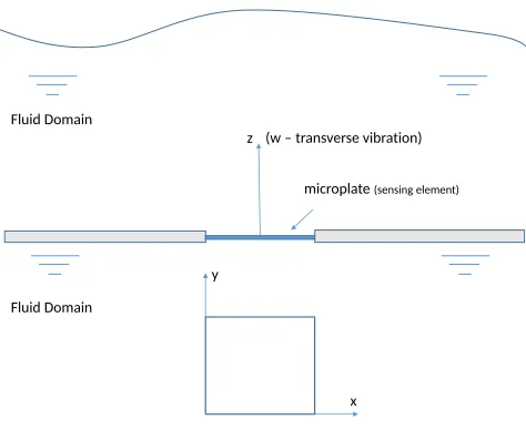
The fluid-plate coupling system is illustrated in Figure1, in which a microplate acting as a sensing element is immersed in a compressible viscous fluid and is stimulated into a small transverse oscillation (along z axis). The governing equation for the forced vibration of a rectangular isotropic plate ignoring the effects of rotatory inertia and transverse shear deformation is given by
D(∂
4w ∂x4 + 2
∂4w ∂x2y2+
∂4w ∂y4) +ρph
∂2w
∂t2 =F(x, y, t) (2.13)
where D=Eh3/12(1−υ2) is the flexural rigidity, E is the Young’s modulus and υ is the poisson’s ratio.ρpis the density of plate andhis the plate thickness.F(x, y, t)is a function that
represents the external loading applied on the plate, which includes the excitation force and the hydrodynamic loading of the fluid. However, for the fluid-plate interaction, this classical thin plate theory is only valid in the frequency range [29]
ωh
πcs<0.1 (2.14)
where cs=pE/(2ρp(1 +υ)) is the shear wave speed of the material. Taking a 5µm thick
200µm square silicon microplate as an example, the above condition is satisfied within the frequency band of 20MHz, which is adequately large for the frequency analysis of microplates that conducted in this paper. The deflection of plate in Eq. (2.13) is expanded as a series form
w(x, y, t) =
∞ X
m=1 ∞ X
n=1
WmnXm(x)Yn(y)·θ(t) (2.15)
whereθ(t)is a time dependent function andWmn is the coefficient of each term in the series
expansion of plate transverse displacement. In a harmonic vibration,θ(t) = sin(ωFt+ϑ),ϑis the
initial phase difference.Xm(x)andYn(y)are the mode shape functions, which need to satisfy the
boundary conditions in bothxandydirections, respectively. In this work,Xm(x)andYn(y)are
chosen as the beam mode shape functions with the same boundary conditions [34], for example
Xm(x)is given by
Xm(x) =A1cosh (kmx) +A2cos (kmx) +A3sinh (kmx) +A4sin (kmx) (2.16)
wherekm=ǫm/La andLa is the plate length along thex-axis.Yn(y) has the same form that
replacextoyandLatoLbin Eq. (2.16) respectively. The coefficientsǫm, A1, A2, A3, A4are given
by the corresponding beam boundary conditions [5,34].
(c) Boundary conditions at the fluid-plate interface
For a small oscillation of the fluid-plate coupling system, at the interface layer, the fluid has no velocity relative to the plate [36]. This condition is known as theno-slip condition, which is stated by the following equality constraints
∂up
∂t =v f
, σ~p=~σf (2.17)
whereupis the displacement vector of the plate. The superscripts “f" and “p" are used to indicate
6
rs
p
a
.r
o
y
a
ls
o
c
ie
ty
p
u
b
lis
h
in
g
.o
rg
P
ro
c
R
S
o
c
A
0
0
0
0
0
0
0
..
..
..
..
..
..
..
..
..
..
..
..
..
..
..
..
..
..
..
..
..
..
..
..
..
..
..
..
..
of fluid is equal to the velocity of the plate, and the stresses along fluid boundary(~σf)are the
same with that on plate surface (~σp). Expanding the above boundary conditions in Cartesian
coordinates(~x, ~y, ~z), the vector potentialψis defined as
ψ=ψx~x+ψy~y+ψz~z (2.18)
The velocity field of the fluid in Eq. (2.4) is expanded as
vfx= ∂φ ∂x+
∂ψz ∂y −
∂ψy ∂z
vfy= ∂φ ∂y +
∂ψx ∂z −
∂ψz ∂x
vfz= ∂φ ∂z+
∂ψy ∂x −
∂ψx ∂y
(2.19)
The velocity field of a vibrating plate is expressed in terms of its flexural waves (bending waves) and given by [37]
vpx=−h
2
∂2w ∂x∂t
vpy=− h
2
∂2w ∂y∂t
vpz=∂w ∂t
(2.20)
Supposing the fluid-plate contact interface is located atz= 0, the no-slip boundary condition of the velocity field is expressed as
vfx=vpx|z=0, vfy=vpy|z=0, vfz=vpz|z=0 (2.21)
(d) Hydrodynamic force on a rectangular plate
In this section, analytical solutions for the hydrodynamic forces that apply on the fluid-loaded rectangular plates are derived. When a plate is immersed in fluid and is excited into vibration, the motion of plate generates a new stress field of fluid on both sides of the plate. The hydrodynamic loadingFhydro(x, y,0, t)on the transverse motion of the plate is determined from the difference
of hydrodynamic forces between the top surface and the bottom surface of the plate
Fhydro(x, y,0, t) =Fhydro(x, y,0−, t)−Fhydro(x, y,0+, t) (2.22)
whereFhydro(x, y,0−, t)andFhydro(x, y,0+, t)represent the applied hydrodynamic forces on
the bottom side and the top side of the plate, respectively. As the thickness of the plate is thin, the hydrodynamic forces of the two sides are equal to each other but are of opposite direction
Fhydro(x, y,0−, t) =−Fhydro(x, y,0+, t) (2.23)
According to theno-slip condition, the surface hydrodynamic force is given by the boundary fluid stresses
Fhydro(x, y,0+) =−σz+h
2
∂τzx
∂x + ∂τzy
∂y
(2.24)
whereσz, τzx, τzy are the normal and shear stresses of fluid at the boundary. In general, the six
7 rs p a .r o y a ls o c ie ty p u b lis h in g .o rg P ro c R S o c A 0 0 0 0 0 0 0 .. .. .. .. .. .. .. .. .. .. .. .. .. .. .. .. .. .. .. .. .. .. .. .. .. .. .. .. ..
of fluid pressure and velocity field
σx=−p+ 2µ∂v f x ∂x −
2 3µ
∂vfx ∂x +
∂vyf ∂y +
∂vfz ∂z
!
σy=−p+ 2µ ∂vfy
∂y −
2 3µ
∂vfx ∂x +
∂vyf ∂y +
∂vfz ∂z
!
σz=−p+ 2µ∂v f z ∂z −
2 3µ
∂vfx ∂x +
∂vyf ∂y +
∂vfz ∂z
!
τxy=τyx=µ ∂vfy
∂x + ∂vxf
∂y !
τyz=τzy=µ ∂v f z ∂y +
∂vfy ∂z
!
τzx=τxz=µ ∂v f x ∂z +
∂vzf ∂x
!
(2.25)
Due to the continuous condition of stresses at the contact interface, the hydrodynamic loading on the plate is determined by the motion of fluid. Substituting the expanded expressions of velocity field in Eq. (2.20) into the above formula of fluid stress tensor, the fluid stresses
σz, τzx, τzyare then expressed in terms of the scalar and the vector potentials.
σz=−2µ∇2φ+ρf0φ˙+ 2µ ∂ 2
φ ∂z2 +
∂2ψy ∂x∂z +
∂2ψx ∂y∂z
!
(2.26)
τzx=µ 2 ∂ 2φ ∂x∂z +
∂2ψz ∂y∂z −
∂2ψx ∂y∂x −
∂2ψy ∂z2 +
∂2ψy ∂x2
!
(2.27)
τzy=µ 2∂ 2φ ∂y∂z +
∂2ψy ∂x∂y−
∂2ψz ∂x∂z −
∂2ψx ∂y2 +
∂2ψx ∂z2
!
(2.28)
The scalar and the vector potentialsφ, ψin the Helmholtz-type equations (2.9) and (2.10) can be solved using a double Fourier transform method. Applying the Fourier integral transform in the
x, ydomain, the solutions of potential fieldsφ, ψare given in the following convolution integral forms
φ(x, y, z) = 1 4π2
∞ZZ
−∞ A·exp
ikxx+ikyy+i q
k2 l −k
2 x−ky2·z
dkxdky (2.29)
ψ(x, y, z) = 1 4π2
∞ZZ
−∞ B·exp
ikxx+ikyy+i q
k2
s−k2x−ky2·z
dkxdky (2.30)
whereAandB(which contains three componentsBx, By, Bz) are unknown coefficients that need
to be determined from the boundary conditions.kx, kyare transformed longitudinal and lateral
wave numbers in frequency domain.Bx, By, Bzare the coefficients for each component of vector
fieldψx, ψy, ψz, respectively. Substituting the Fourier transformed solution of the scalar and the
8 rs p a .r o y a ls o c ie ty p u b lis h in g .o rg P ro c R S o c A 0 0 0 0 0 0 0 .. .. .. .. .. .. .. .. .. .. .. .. .. .. .. .. .. .. .. .. .. .. .. .. .. .. .. .. ..
andB) are derived.
i q
k2 l −k
2
x−ky2·A+ikyBx−ikxBy= ˜˙w kxA+
q
k2s−k2x−ky2·By+kyBz=h
2kxw˜˙
−kyA+ q
k2
s−kx2−k2y·Bx+kxBz=h
2kyw˜˙
−kxBx−kyBy+ q
k2s−k2x−ky2·Bz= 0
(2.31)
The coefficients A, Bx, By, Bz are then determined in closed-forms from the above linear
equations as
A=
−h(kx2+k2y) + 2i(k2x+ky2)/ q
k2 l −k
2 x−k2y
2(k2 x+ky2+
q k2
l −k 2 x−ky2
q k2
s−k2x−ky2)
−q i k2
l −k 2 x−k2y
˜˙
w (2.32)
Bx=−
hky q
k2 l −k
2
x−k2y−2iky
2(k2 x+k2y+
q k2
l −k 2 x−ky2
q k2
s−k2x−ky2)
˜˙
w (2.33)
By=
−hkx q
k2 l −k
2
x−k2y+ 2ikx
2(k2 x+k2y+
q k2
l −k 2 x−k2y
q k2
s−kx2−k2y)
˜˙
w (2.34)
Bz= 0 (2.35)
Subsequently, an analytical expression of the hydrodynamic force that is applied on the plate immersed in a viscous and compressible fluid is obtained with the closed-form solutions of these coefficients (A, Bx, By, Bz). Substituting the solutions of potential fields in Eqs. (2.29) and (2.30)
into Eq. (2.24), and the formulas of hydrodynamic force is given by
Fhydro(x, y,0+) =
1 4π2
∞ZZ
−∞
T(kx, ky) ˜˙wexp(ikxx+ikyy)dkxdkx (2.36)
where the inner functionT(kx, ky)contains two parts as
T(kx, ky) =−T1(kx, ky) +h
2T2(kx, ky) (2.37)
T1(kx, ky)andT2(kx, ky)are two coefficient functions corresponding to the normal stress (σz)
and the shear stresses (τzx, τzy) of the fluid, and given by
T1= [2µ(k2x+k 2
y)−iρf0ω]A ′
−2µ(kx q
k2l −k2x−k2yB ′ y−ky
q
k2l −k2x−k2yB ′
x) (2.38)
T2=−iµ[2 q
k2 l −k
2
x−k2y(k2x+kx2)A ′
+ky(kl2−2k 2
x−2k2y)B ′
x+kx(−kl2+ 2k 2
x+ 2k2y)B ′ y]
(2.39) whereA′=A/w, B˜˙ ′x=Bx/w, B˜˙
′
y=By/w˜˙. As such, Eqs. (2.32)-(2.39) provide a series of analytical
expressions that can straightforwardly determine the hydrodynamic force applying on the vibrating plate at the fluid-plate interface. This is the major novelty for the theoretical modelling of fluid-plate coupling system that was developed in this work.
9
rs
p
a
.r
o
y
a
ls
o
c
ie
ty
p
u
b
lis
h
in
g
.o
rg
P
ro
c
R
S
o
c
A
0
0
0
0
0
0
0
..
..
..
..
..
..
..
..
..
..
..
..
..
..
..
..
..
..
..
..
..
..
..
..
..
..
..
..
..
form of acoustic pressure as
p(x, y,0+) = 1 4π2
∞ZZ
−∞
ρf0ωw˜˙exp(ikxx+ikyy) q
k2l −k2x−k2y
dkxdkx (2.40)
Eq. (2.40) had been received wide applications in the study of plate borne acoustic radiation [12–
14,29]. Note, Eq. (2.36) is also applicable to the cases that the viscosity of the fluid is low.
(e) Fluid-plate interaction model
The external excitation force is assumed to be a concentrated force (Fex) applied at a point
(x0, y0). The whole external forceF(x, y, t)in Eq. (2.13) then equals to
F(x, y) =Fexδ(x−x0)δ(y−y0) +Fhydro (2.41)
By substitution Eqs. (2.15), (2.36) and (2.41) into Eq. (2.13) and application of the Galerkin method, the following model for the fluid-loaded rectangular plates is obtained
∞ X
m
∞ X
n
(Γmnqr+iωImnqr){Wmn}=Fqr q, r= 1,2,· · ·,∞ (2.42)
whereFqris a generalized form of external force and given by
Fqr= ZZ
S
Fexδ(x−x0)δ(y−y0)Xq(x)Yr(y)dx dy (2.43)
andΓmnqris a modal coefficient of plate stiffness and given by
Γmnqr= (
Mωmn2 −ω2
(m=qandn=r)
0 (m6=qorn6=r) (2.44)
whereMis the mass of plate andωmnis the(m, n)mode natural frequency of the platein vacuo.
Analytical solutions of the natural frequencies of rectangular plates with ordinary boundary conditions have been well studied [38]. For example, the natural frequencies of an all edges clamped plate can be evaluated using the following equation
ωmn2 = D ρph
k
4 m+ 2
RR S
Xm(x)Xm,xx(x)Yn(y)Yn,yy(y)dxdy RR
S X2
m(x)Yn2(y)dxdy
+k4n
(2.45)
whereXmandYnare the mode shape functions given by Eq. (2.16).
Imnqr is a fluid-loading impedance that is induced by acoustic radiation and viscosity.Imnqr
reflects the coupling effect that is linked by two discrete vibrational modes of plate, namely(m, n)
and(q, r).Imnqris expressed in terms of the hydrodynamic force as
Imnqr= 1
4π2 ZZ∞
−∞
T(kx, ky)χmn(kx, ky)χ∗qr(kx, ky)dkxdky (2.46)
where χmn(kx, ky) and χ∗qr(kx, ky) are double Fourier transform of the plate mode shape
functions. The expression ofχmn(kx, ky)is χmn(kx, ky) =
ZZ
S
Xm(x)Yn(y) exp(−i(kxx+kyy)) (2.47)
andχ∗qr(kx, ky)is a conjugated form of Eq. (2.47) with the indices ofqandr. After substituting
the mode shape functions (2.16) into Eqs. (2.46) and (2.47), the fluid-loaded impedanceImnqr
is expanded into a 6 dimensional integration, which is very tedious to evaluate numerically. Fortunately, the inner functions χmn and χ∗qr can be solved in closed forms for most of
10
rs
p
a
.r
o
y
a
ls
o
c
ie
ty
p
u
b
lis
h
in
g
.o
rg
P
ro
c
R
S
o
c
A
0
0
0
0
0
0
0
..
..
..
..
..
..
..
..
..
..
..
..
..
..
..
..
..
..
..
..
..
..
..
..
..
..
..
..
..
of χmn(kx, ky) for an all clamped rectangular plate is derived and expressed as the follows.
Solutions for the plates with other boundary conditions are similar.
χmn(kx, ky) = [Ixc(m, kx)−iIxs(m, kx)]·[Iyc(n, ky)−iIys(n, ky)] (2.48)
where
Ixc(m, kx) =
1 2(km2 +k2x)
ekmLa(kxsin(Lakx) +kmcos(Lakx))+
e−kmLa(kxsin(Lakx)−kmcos(kxLa))
−1
2
sin(La(km+kx)) km+kx +
sin(La(km+kx)) km−kx
−αm
1 2(k2m+k2x)
ekmLa(kxsin(Lakx) +kmcos(kxLa))+
e−kmLa(kxsin(Lakx)−kmcos(kxLa))−2km
+ 1
2
cos(La(km+kx))−1
km+kx +
cos(La(km−kx))−1 km−kx
(2.49)
Ixs(m, kx) =
1 2(k2
m+kx2)
ekmLa(kmsin(Lakx)−kxcos(Lakx))−
e−kmLa(kmsin(Lakx)−kxcos(kxLa)) + 2kx
+1 2
cos(La(km+kx))−1 km+kx
−cos(La(km−kx))−1
km−kx
−αm
1 2(k2
m+k2x)
ekmLa(kmsin(Lakx)−
kxcos(kxLa)) +e−kmLa(kmsin(Lakx) +kxcos(kxLa))
+ 1
2
sin(La(km+kx)) km+kx
−sin(La(km−kx))
km−kx
(2.50)
The functions ofIyc(n, ky)andIys(n, ky)have the same forms withIxc(m, kx)andIxs(m, kx)by
replacingkmtoknandLatoLb, respectively. As such,Imnqrreduces to a double integral form,
which can be evaluated numerically by an ordinary integration method.
Since the fluid impedanceImnqris a complex function, we can write it in a form with separated
real and imaginary parts as [29]
Imnqr=rmnqr−iω×mmnqr (2.51)
wherermnqrrepresents an energy loss of the plate due to the acoustic radiation and the viscosity
of the fluid, and the termmmnqrcauses as an additionally inertial action to the plate motion [12].
In other words, the term rmnqr gives rise to the damping of the vibration, whereas the term mmnqr contributes an added masseffect to the fluid-loaded plate. The added mass factor and
damping mechanism of a loaded plate can be analysed through the investigation of fluid-loading impedanceImnqr.
Eq. (2.42) is obtained using a Galerkin procedure with an assumption that the mode shapes of the plate are orthogonal. In so doing, the closed-form expressions for the inner functions of fluid-loading impedance are derived, as shown in Eqs. (2.49) and (2.50). A more general model is derived from the principle of virtual work for the plates that their mode shapes are not completely orthogonal, for example the cantilever plates.
δ·Up+ ZZ
S ρsh∂
2w
∂t2δwdxdy− ZZ
S
11
rs
p
a
.r
o
y
a
ls
o
c
ie
ty
p
u
b
lis
h
in
g
.o
rg
P
ro
c
R
S
o
c
A
0
0
0
0
0
0
0
..
..
..
..
..
..
..
..
..
..
..
..
..
..
..
..
..
..
..
..
..
..
..
..
..
..
..
..
..
whereUpis the potential energy of plate,
Up=D
2
ZZ
S
∂2w ∂x2 +
∂2w ∂y2
2
−2(1−ν)
" ∂2w ∂x2
∂2w ∂y2 −
∂2w ∂x∂y
2#
dxdy (2.53)
andδwis the virtual displacement of plate. Substituting the solution or expression ofUp,w(Eq.
(2.15)) and external forceF(Eq. (2.41)) into Eq. (2.52), an analytical solution based on the principle of virtual work is derived.
∞ X
m
∞ X
n
Up,mnqr−ω2Tp,mnqr∗ +iω Imnqr
2
{Wmn}=Fqr q, r= 1,2,· · ·,∞ (2.54)
where
Up,mnqr=D
2
ZZ
S
Xm,xx(x)Xq,xx(x)Yn(y)Yr(y) +Xm(x)Xq(x)Yn,yy(y)Yr,yy(y)+
2νXm,xx(x)Xq(x)Yn(y)Yr,yy(y) + 2(1−ν)Xm,x(x)Xq,x(x)Yn,y(y)Yr,y(y)
dxdy
(2.55)
Tp,mnqr∗ =1
2ρph
ZZ
S
Xm(x)Xq(x)Yn(y)Yr(y)dxdy (2.56)
Eq. (2.54) can also be written in the following matrix form
{−ω2[M] +iω[C] + [K]}{W}= 0 (2.57) whereM,CandKare mass, damping and stiffness matrices of the vibration system respectively,
and their elements are given by
Kij= 2Up,mnqr
Mij= 2Tp,mnqr∗ +mmnqr Cij=rmnqr
i=l(q−1) +r, j=l(m−1) +n, l∈N+
3. Numerical simulation
(a) Simulation process
The dynamics of the fluid-loaded plate at a prescribed frequency is determined from either Eq. (2.42) or Eq. (2.54). As the study is mainly on the first few vibrational modes in the current work,
9×9terms of mode shape functions are used for the vibration analysis of microplates in each simulation. The vibrational deflection of the fluid-loaded plate is then computed using Eq. (2.15), once the solution ofWmnis obtained. The frequency response function of the fluid-loaded plate
over a specified frequency range is produced by performing the simulation at a series of linearly spaced excitation frequencies within this range.
The material properties of the microplate (siliconh100i) and the fluid (water) used in the numerical simulation are
•Plate Length:La= 100µm
•Plate Width:Lb= 100µm
•Plate Thickness:h= 5µm
•Plate Young’s Modulus:E= 150GP a
•Plate Poisson’s Ratio:ν= 0.17
12
rs
p
a
.r
o
y
a
ls
o
c
ie
ty
p
u
b
lis
h
in
g
.o
rg
P
ro
c
R
S
o
c
A
0
0
0
0
0
0
0
..
..
..
..
..
..
..
..
..
..
..
..
..
..
..
..
..
..
..
..
..
..
..
..
..
..
..
..
..
•Water Density:ρf= 1000kg/m3
•Water Viscosity:µ= 1.003cP
•Acoustic Speed (in water):c= 1482m/s
Nevertheless, the most difficult part in the numerical simulation is the evaluation of fluid-loading impedanceImnqr. As the simulation is carried out on microscale plates(10−6), direct
numerical evaluation of the fluid impedance may encounter arithmetic overflow or errors. To avoid this issue, the virtual wave numbers (kx, ky) in the fluid impedance are normalised with
respect to the acoustic wave number (k=ω/c) [14], namely kx=kKx, ky=kKy. The fluid
impedance is then evaluated by
˜
Imnqr= k 2
4π2 ZZ∞
−∞
T(Kx, Ky)χmn(Kx, Ky)χ∗qr(Kx, Ky)dKxdKy (3.1)
The fluid impedance involves a double integration over infinity and a square root singularity. The fluid-loading impedance is numerically evaluated using a Quasi-Monte Carlo method, which is an effective means to perform the complicated numerical integration with singularities. The double infinite integration ([−∞,∞],[−∞,∞]) is truncated into finite ranges ([−l, l],[−l, l]) in the process of numerical simulation. Convergence is achieved when the truncated ranges are sufficiently large. The values of the fluid impedanceI1111,I1212,I2222andI3333for an all edges
clamped plate over a series of different truncated ranges are computed to study the convergence. As proved by the results shown in Fig. 1, the values of I1111, I1212, I2222 and I3333 start to
converge whenlis larger than 10. Note, for different boundary conditions, the truncated integral ranges are different for achieving convergent results of the fluid impedance.
(b) Damping mechanism
This section presents a study on the damping mechanism of fluid-loaded microplates. The damping effects caused by the acoustic radiation and the viscous dissipation are examined separately. If the fluid is assumed to be inviscid and incompressible (µ= 0andc→ ∞), there is no damping and only the inertial force of the fluid (added mass) takes effect to the motion of fluid-loaded microplates. If the fluid is assumed to be inviscid and compressible (µ= 0), the damping of the fluid-loaded plate is mainly contributed by the acoustic radiation. In this work, three different cases of fluid-loading are studied: (i) no damping effect is taken into account,
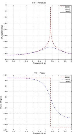
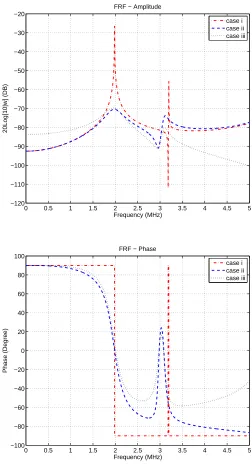
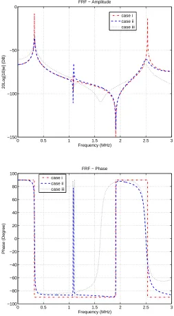
µ= 0andc→ ∞; (ii) the fluid is assumed to be inviscid but the acoustic radiation is considered (compressible fluid), µ= 0 andc= 1482m/s; (iii) both the acoustic damping and the viscous damping are considered,µ= 1.003cP andc= 1482m/s. The numerical simulation is carried out on three different boundary conditions of microplates: all clamped (CCCC), two opposite edges clamped and the rest are free (CFCF), cantilever (CFFF). The frequency response functions (FRF) of each type microplate under these three different fluid-loading cases (i-iii) are illustrated in Figures3,4and5, respectively.
The natural frequencies and damping ratios of each microplate can be determined from the FRF curves by a modal analysis procedure [32]. It was proved by previous work [32] that the predicted resonant frequencies for the three fluid-loaded microplates are well matched with the results of a Rayleigh-Ritz model [5] and the experimental testing [32]. In Table1, the damping ratios of the three different types (boundary conditions) microplates that are predicted using the theoretical model are compared and validated with the experimental results. For the case (ii), the damping ratios of each microplate are 0.117 (CCCC), 0.089 (CFCF) and 0.017 (CFFF). For the case (iii) that the viscosity is considered, the damping ratios for each microplate are 0.118, 0.095 and 0.019, respectively, which are almost the same with the values of case (ii).
13
rs
p
a
.r
o
y
a
ls
o
c
ie
ty
p
u
b
lis
h
in
g
.o
rg
P
ro
c
R
S
o
c
A
0
0
0
0
0
0
0
..
..
..
..
..
..
..
..
..
..
..
..
..
..
..
..
..
..
..
..
..
..
..
..
..
..
..
..
[image:13.595.170.426.147.210.2]..
Table 1. Theoretical and experimental results on damping ratios of the three types 300µm×300µm×5µmof
microplates (reproduced from [31])
C-F-F-F C-F-C-F C-C-C-C Modes Theo. Expe. Theo. Expe. Theo. Expe.
1st 2.83% 2.13% 2.38% 1.47% 3.21% 1.81% 2nd - - 0.21% 0.27% 0.20% 0.32% 3rd(4th) 0.38% 0.26% 0.17% 0.18% 0.02% 0.08%
mode is evaluated from the damping ratio as
Q= 1
2ζ (3.2)
whereζ denotes the damping ratio. Therefore, the cantilever microplate possesses the highest Q-factor (26.3) as well as the sensitivity among these three types microplates (Q-factors: 4.24 for CCCC and 5.26 for CFCF).
As shown in the Figures3,4and5, the FRF trends around the region of first vibrational modes for case (ii) and case (iii) of each type microplate are very close to each other. It therefore results in nearly the same natural frequencies and damping ratios for the case (ii) and case (iii) of each microplate. From the simulation results at the fundamental vibrational mode, we found that the acoustic radiation (rather than the viscous relaxation) mainly contributes the damping of fluid-loaded microplates.
In other words, if only the first vibrational mode is considered and the fluid viscosity is low (like water), the viscous damping effect can be ignored for the fluid-loaded microplates. It was also observed that the effect of fluid viscosity does affect the higher vibrational modes (2nd and 3rd in Figures4and5) on the microplates, in particular for CFFF type microplates. This conclusion is very different with the work that studied the fluid-loaded micro-cantilevers [6,22], in which the viscous dissipation is found to be the dominant damping mechanism. This can be explained using a modified Reynolds number given by [6]1, which is expressed as
Re=ρfωwet,0b
2
4µ (3.3)
whereρfis the fluid density,µis the fluid viscosity,ωwet,0is the damped resonant frequency of a
micro-structure andbis the characteristic width. A100µm×100µm×5µmmicro-cantilever plate and a100µm×5µm×5µmmicro-cantilever beam with the same material properties are taken as examples. The Reynolds number of this cantilever microplate is5118, whereas the Reynolds number of the micro-cantilever beam is only12.29, which is over400times less than the value of the microplate. It was found that the fluid-loaded microplates with other boundary conditions (CCCC or CFCF) have much high Reynolds numbers, due to their high natural frequencies. For those cases with large Reynolds number, it is applicable to assume the fluid to be inviscid. Therefore, it is accurate enough to consider the acoustic radiation solely for the damping analysis of fluid-loaded microplates when the viscosity is low. Without considering the viscosity, the fluid impedanceImnqrin Eq. (2.46) reduces into the following form of acoustic impedanceImnqra .
Imnqra = ρfω
4π2 ZZ∞
−∞
χmn(kx, ky)χ∗qr(kx, ky) q
k2−k2 x−k2y
dkxdky (3.4)
Pierceet al.[33] proposed a method that transforms the integration of Eq. (3.4) from Cartesian coordinates to polar coordinates, by which the closed-form solution of the acoustic impedance
Imnqra can be obtained [5].
1This modified Reynolds number is proposed by Saderet al.[6]. The conventional Reynolds number [30] that is associated
14
rs
p
a
.r
o
y
a
ls
o
c
ie
ty
p
u
b
lis
h
in
g
.o
rg
P
ro
c
R
S
o
c
A
0
0
0
0
0
0
0
..
..
..
..
..
..
..
..
..
..
..
..
..
..
..
..
..
..
..
..
..
..
..
..
..
..
..
..
..
(c) High viscosity effects
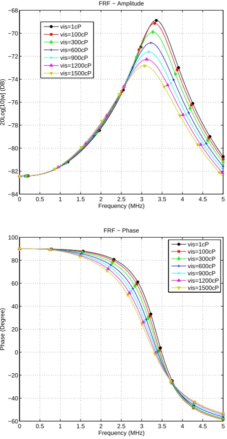
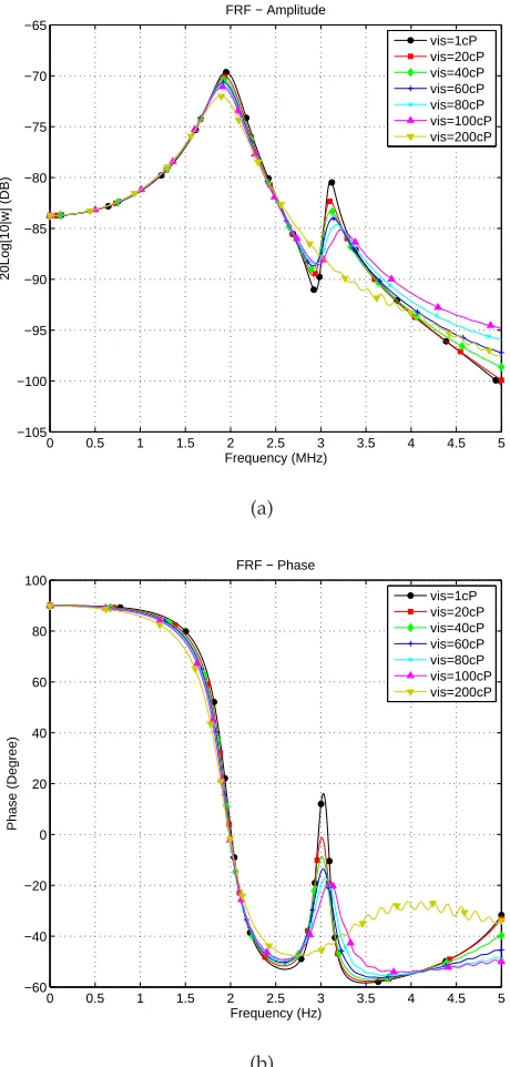
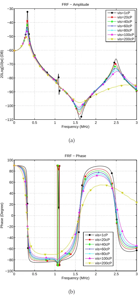
In this section, the highly viscous fluid-loading effect on the dynamics of microplates is studied. Numerical simulation is conducted on the fluid with 7 different viscosities from 1 cP to 1500 cP (or 1 cP to 200 cP)2. The frequency response functions (FRF) for the three types of microplates that are immersed in different fluids with high viscosities are plotted in Figures 6, 7 and8, respectively. Figure6demonstrates that the dynamics of a submerged microplate (CCCC) is only slightly influenced by the highly viscous fluid, even when the viscosity is up to 1500 cP. However, as shown in Figures 7and8, the fluid with high viscosity substantially affects the vibrational behaviour of the other two types of microplates (CFCF and CFFF ). When the viscosity of the fluid is higher than 200 cP, the second vibrational modes of the CFCF and CFFF microplates are completely attenuated due to the high viscous energy dissipation. Thus, the CCCC microplates are much more resistive to the viscous damping than the CFCF and CFFF microplates. In other words, it is more suitable to apply a CCCC type of microplate in a high viscous fluid media as the sensing element. A CFCF or CFFF type microplate, which has high Q-factor (sensitivity), may lose its sensing function when it is being used in a media with high viscosity (i.e. over 200 cP).
It is also observed that the resonant frequencies of microplates are decreased when the viscosity values of the fluid are increased. Thus, the fluid viscosity contributes an additionaladded masseffect to the vibration of microplates. Further quantitative study [40] shows that the resonant frequency shift is approximately linear with respect to the increase rate of the viscosity value. For a CCCC100µm×100µm×5µmmicroplate, Figure9illustrates an approximate linear relationship between the changes of fundamental resonant frequency and the fluid viscosity values. Cedric Ayela and Liviu Nicu [2] experimentally studied the effect of fluid viscosity to the dynamics of fluid-loaded circular microplates. A similar conclusion (Figures. 7 and 12 in [2]) was reached from their experimental results.
4. Conclusion
In this paper, the dynamics of microscale plates immersed in a viscous and compressible fluid is studied. To investigate the damping mechanism of the fluid-loading effect on the microplates, a theoretical modelling considering both acoustic damping and viscous damping is developed. In this model, the analytical solution for the fluid-loading impedance is obtained using a Fourier transform technique. To study the damping mechanism of fluid-loaded microplates, a number of cases for the microplates under different fluid-loading conditions are simulated using the proposed theoretical modelling.
The numerical simulation results reveal that the acoustic radiation contributes the dominant damping of fluid-loaded microplates, and the viscous fluid-loading effect can be ignored when the viscosity of the fluid is lower than 10 cP. Compared with the micro-cantilevers, the microplates show higher Q-factors (sensitivity) and are more resistive to the viscous effect of fluid-loading. It is also concluded that the cantilever type of microplates possesses the highest sensitivity among the three types of boundary conditions (CCCC, CFCF and CFFF). However, the dynamics of the microplate with all edges clamped (CCCC) is much less influenced by viscous dissipation of the fluid.
2(1 cP, 100 cP, 300 cP, 600 cP, 900 cP, 1200 cP, 1500 cP), or (1 cP, 20 cP, 40 cP, 60 cP, 80 cP, 100 cP, 200 cP). The viscosity of water
is approximately 1 cP, whereas 1500 cP is the viscosity of100%glycerol at25◦C. The other viscosity of the fluid can be
15
rs
p
a
.r
o
y
a
ls
o
c
ie
ty
p
u
b
lis
h
in
g
.o
rg
P
ro
c
R
S
o
c
A
0
0
0
0
0
0
0
..
..
..
..
..
..
..
..
..
..
..
..
..
..
..
..
..
..
..
..
..
..
..
..
..
..
..
..
..
5. Figures & Tables
z
x y
Fluid Domain
Fluid Domain
[image:15.595.175.412.156.350.2]microplate (sensing element) (w – transverse vibration)
16
rs
p
a
.r
o
y
a
ls
o
c
ie
ty
p
u
b
lis
h
in
g
.o
rg
P
ro
c
R
S
o
c
A
0
0
0
0
0
0
0
..
..
..
..
..
..
..
..
..
..
..
..
..
..
..
..
..
..
..
..
..
..
..
..
..
..
..
..
..
2 4 6 8 10 100 300 500 −4
−2 0 2 4 6 8 10x 10
−3
Impedance Integral Truncated Range [−l,l]
Impedance
I
1111
real part imaginary part
2 4 6 8 10 100 300 500 −1
0 1 2 3 4 5x 10
−3
Impedance Integral Truncated Range [−l,l]
Impedance
I1212
real part imaginary part
2 4 6 8 10 100 300 500 −0.5
0 0.5 1 1.5 2 2.5 3 3.5x 10
−3
Impedance Integral Truncated Range [−l,l]
Impedance
I
2222
real part imaginary part
2 4 6 8 10 100 300 500 −0.5
0 0.5 1 1.5 2 2.5x 10
−3
Impedance Integral Truncated Range [−l,l]
Impedance
I3333
[image:16.595.134.468.113.431.2]real part imaginary part
Figure 2. Convergence study of truncated double integral ranges ([−l, l]and[−l, l]) in the evaluation of fluid-loading
impedanceImnqr. Here,I1111, I1212, I2222andI3333are examined.
Ethics statement. This work did not involve any active collection of human data.
Data accessibility statement. This work is mainly on the theoretical simulation.
Competing interests statement. We have no competing interests.
Authors’ contributions. X Ma conceived the research idea of utilising the microplates as
biosensing elements. Z Wu developed the mathematical models and performed the simulations. Z Wu and X Ma interpreted the results and wrote the paper. Both authors gave final approval for publication.
AcknowledgementsThe authors wish to acknowledge the funding support EPSRC, as well as
an anonymous reviewer for his/her excellent comments.
Funding This research was supported by EPSRC (EP/D033284/1).
References
17
rs
p
a
.r
o
y
a
ls
o
c
ie
ty
p
u
b
lis
h
in
g
.o
rg
P
ro
c
R
S
o
c
A
0
0
0
0
0
0
0
..
..
..
..
..
..
..
..
..
..
..
..
..
..
..
..
..
..
..
..
..
..
..
..
..
..
..
..
..
0 0.5 1 1.5 2 2.5 3 3.5 4 4.5 5
−90 −80 −70 −60 −50 −40 −30 −20 −10 0
Frequency (Hz)
20Log[10|w] (DB)
FRF − Amplitude
case i case ii case iii
0 0.5 1 1.5 2 2.5 3 3.5 4 4.5 5
−100 −80 −60 −40 −20 0 20 40 60 80 100
Frequency (Hz)
Phase (Degree)
FRF − Phase
[image:17.595.167.419.113.579.2]case i case ii case iii
Figure 3.FRF at point(La/2, Lb/2) of forced fibration of a fluid-loaded 100µm×100µm×5µmCCCC microplate (frequency range is from 1kHz to 5MHz)
Sensors and Actuators B, 110(1):125–36, 2005.
2. Liviu Nicu and C. Ayela. Micromachined piezoelectric membranes with high nominal quality factors in newtonian liquid media: A lamb’s model validation at the microscale.Sensors and Actuators B (Chemical), 123(2):860–868, 2007.
3. Alava1, F. Mathieu1, P. Rameil, Y. Morel, C. Soyer, D. Remiens and L. Nicu. Piezoelectric-actuated, piezoresistive-sensed circular micromembranes for label-free biosensing applications.Applied Physics Letters, 97, 093703, 2010.
Appl. Phys. Lett. ;
18
rs
p
a
.r
o
y
a
ls
o
c
ie
ty
p
u
b
lis
h
in
g
.o
rg
P
ro
c
R
S
o
c
A
0
0
0
0
0
0
0
..
..
..
..
..
..
..
..
..
..
..
..
..
..
..
..
..
..
..
..
..
..
..
..
..
..
..
..
..
0 0.5 1 1.5 2 2.5 3 3.5 4 4.5 5
−120 −110 −100 −90 −80 −70 −60 −50 −40 −30 −20
Frequency (MHz)
20Log[10|w] (DB)
FRF − Amplitude
case i case ii case iii
0 0.5 1 1.5 2 2.5 3 3.5 4 4.5 5
−100 −80 −60 −40 −20 0 20 40 60 80 100
Frequency (MHz)
Phase (Degree)
FRF − Phase
[image:18.595.165.417.116.582.2]case i case ii case iii
Figure 4.FRF at point(La/2, Lb/4) of forced vibration of a fluid-loaded100µm×100µm×5µmCFCF microplate (frequency range is from 1kHz to 5MHz)
immunosensor array.Biosensors and Bioelectronics, 24(4):638–432, 2008.
5. Z. Wu, X. Ma, P. Brett, and J. Xu. Vibration analysis of submerged micro rectangular plates with distributed mass loading.Proceedings A of the Royal Society, 465(A):205–216, 2009. 6. J. E. Sader. Frequency response of cantilever beams immersed in viscous fluids with
applications to the atomic force microscope.Journal of applied physics, 84(1):64–76, 1998. 7. A.H. Nayfeh and M. I. Younis. A new approach to the modeling and simulation of flexible
microstructures under the effect of squeeze-film damping. Journal of Micromechanics and Microengineering, 14(2):170–181, 2004.
19
rs
p
a
.r
o
y
a
ls
o
c
ie
ty
p
u
b
lis
h
in
g
.o
rg
P
ro
c
R
S
o
c
A
0
0
0
0
0
0
0
..
..
..
..
..
..
..
..
..
..
..
..
..
..
..
..
..
..
..
..
..
..
..
..
..
..
..
..
..
0 0.5 1 1.5 2 2.5 3
−150 −100 −50 0
Frequency (MHz)
20Log[10|w] (DB)
FRF − Amplitude
case i case ii case iii
0 0.5 1 1.5 2 2.5 3
−100 −80 −60 −40 −20 0 20 40 60 80 100
Frequency (MHz)
Phase (Degree)
FRF − Phase
[image:19.595.165.418.120.579.2]case i case ii case iii
Figure 5.FRF at point(La/2,0)of forced vibration of a fluid-loaded100µm×100µm×5µmCFFF microplate (frequency range is from 1kHz to 3MHz)
microstructure.Sensors and Actuators, A: Physical, 49(1-2):103–108, 1995.
9. M. Lax. The effect of radiation on the vibrations of a circular diaphragm. Journal of the Acoustical Society of America, 16:5–13, 1944.
10. D. Feit. Pressure radiated by a point-excited elastic plate.Journal of the Acoustical Society of America, 40:1489–1494, 1966.
11. H.G. Davies. Low frequency random excitation of water-loaded rectangular plates.Journal of Sound and Vibration, 15(1):107–126, 1971.
20
rs
p
a
.r
o
y
a
ls
o
c
ie
ty
p
u
b
lis
h
in
g
.o
rg
P
ro
c
R
S
o
c
A
0
0
0
0
0
0
0
..
..
..
..
..
..
..
..
..
..
..
..
..
..
..
..
..
..
..
..
..
..
..
..
..
..
..
..
..
0 0.5 1 1.5 2 2.5 3 3.5 4 4.5 5
−84 −82 −80 −78 −76 −74 −72 −70 −68
Frequency (MHz)
20Log[10|w] (DB)
FRF − Amplitude
vis=1cP vis=100cP vis=300cP vis=600cP vis=900cP vis=1200cP vis=1500cP
0 0.5 1 1.5 2 2.5 3 3.5 4 4.5 5
−60 −40 −20 0 20 40 60 80 100
Frequency (MHz)
Phase (Degree)
FRF − Phase
[image:20.595.181.408.119.557.2]vis=1cP vis=100cP vis=300cP vis=600cP vis=900cP vis=1200cP vis=1500cP
Figure 6. FRFs of a CCCC100µm×100µm×5µmmicroplate immersed in different fluids with high viscosity.
fluid loading on finite and infinite plates.Journal of the Acoustical Society of America, 52(5):1537– 1552, 1972.
13. Y.M. Chang and P. Leehey. Acoustic impedance of rectangular panels.Journal of Sound and Vibration, 64(2):243–256, 1996.
14. W.R. Graham. High-frequency vibration and acoustic radiation of fluid-loaded plates.
Philosophical Transactions of the Royal Society, Series A, 352(1698):1–43, 1995.
15. B. S. Massey. Mechanics of Fluids. Van NOstrand Reinhold Company, Letchworth, Hertfordshire, 1970.
16. C. Atkinson and M. Manrique de Lara. The frequency response of a rectangular cantilever plate vibrating in a viscous fluid.Journal of Sound and Vibration, 300(1):352–367, 2007.
21
rs
p
a
.r
o
y
a
ls
o
c
ie
ty
p
u
b
lis
h
in
g
.o
rg
P
ro
c
R
S
o
c
A
0
0
0
0
0
0
0
..
..
..
..
..
..
..
..
..
..
..
..
..
..
..
..
..
..
..
..
..
..
..
..
..
..
..
..
..
0 0.5 1 1.5 2 2.5 3 3.5 4 4.5 5
−105 −100 −95 −90 −85 −80 −75 −70 −65
Frequency (MHz)
20Log[10|w] (DB)
FRF − Amplitude
vis=1cP vis=20cP vis=40cP vis=60cP vis=80cP vis=100cP vis=200cP
(a)
0 0.5 1 1.5 2 2.5 3 3.5 4 4.5 5
−60 −40 −20 0 20 40 60 80 100
Frequency (Hz)
Phase (Degree)
FRF − Phase
vis=1cP vis=20cP vis=40cP vis=60cP vis=80cP vis=100cP vis=200cP
[image:21.595.178.408.118.599.2](b)
Figure 7. FRFs of a CFCF100µm×100µm×5µmmicroplate immersed in different fluids with high viscosity.
scanning force microscopy cantilevers.Review of Scientific Instruments, 65(8):2532–2537, 1994. 18. W.Y. Shih, X. Li, H. Gu, W. H. Shih, and I.A Aksay. Simultaneous liquid viscosity and density
determination with piezoelectric unimorph cantilevers.Journal of Applied Physics, 89(2):1497– 1505, 2001.
19. J.W.M. Chon, P. Mulvaney, and J.E. Sader. Experimental validation of theoretical models for the frequency response of atomic force microscope cantilever beams immersed in fluids.
22
rs
p
a
.r
o
y
a
ls
o
c
ie
ty
p
u
b
lis
h
in
g
.o
rg
P
ro
c
R
S
o
c
A
0
0
0
0
0
0
0
..
..
..
..
..
..
..
..
..
..
..
..
..
..
..
..
..
..
..
..
..
..
..
..
..
..
..
..
..
0 0.5 1 1.5 2 2.5 3
−110 −100 −90 −80 −70 −60 −50 −40 −30
Frequency (MHz)
20Log[10|w] (DB)
FRF − Amplitude
vis=1cP vis=20cP vis=40cP vis=60cP vis=80cP vis=100cP vis=200cP
(a)
0 0.5 1 1.5 2 2.5 3
−100 −80 −60 −40 −20 0 20 40 60 80 100
Frequency (MHz)
Phase (Degree)
FRF − Phase
vis=1cP vis=20cP vis=40cP vis=60cP vis=80cP vis=100cP vis=200cP
[image:22.595.177.408.115.616.2](b)
Figure 8. FRFs of a CFFF100µm×100µm×5µmmicroplate immersed in different fluids with high viscosity.
20. Y.H. Chen and W.H. Huang. Resonant response of rectangular afm cantilever in liquid.
Chinese Physics Letters, 24(2):363–365, 2007.
21. P. Decuzzi, A. Granaldi, and G. Pascazio. Dynamic response of microcantilever-based sensors in a fluidic chamber.Journal of Applied Physics, 101(2):024303–1–6, 2007.
22. S. Basak and A. Raman. Hydrodynamic loading of microcantilevers vibrating in viscous fluids.Journal of applied physics, 99(11):114906–1–14906–10, 2006.
23
rs
p
a
.r
o
y
a
ls
o
c
ie
ty
p
u
b
lis
h
in
g
.o
rg
P
ro
c
R
S
o
c
A
0
0
0
0
0
0
0
..
..
..
..
..
..
..
..
..
..
..
..
..
..
..
..
..
..
..
..
..
..
..
..
..
..
..
..
..
1cP 100cP 300cP 600cP 900cP 1200cP 1500cP
−18 −16 −14 −12 −10 −8 −6 −4 −2
0x 10
4
1st Mode Natural Frequency Shift (Hz)
Fluid Viscosity
[image:23.595.191.402.114.321.2](a)
Figure 9. Shifts trend of first mode resonant frequency of a C-C-C-C 100µm×100µm×5µmmicroplate under
different values of high viscous damping
structuralâ ˘A¸Sacoustical FSI numerical model to predict natural frequencies of submerged structures with nearby rigid surfaces.Computers & Fluids, 64(15):117â ˘A¸S-126, 2012.
24. J.L. Dohner. The contribution of radiation and viscous loss in a fluid loaded flexural plate wave sensor.Journal of Sound and Vibration, 217(1):113–126, 1998.
25. S.V. Sorokin and A.V. Chubinskij. On the role of fluid viscosity in wave propagation in elastic plates under heavy fluid loading.Journal of Sound and Vibration, 311(3-5):1020–1038, 2008. 26. A. N. GUZ. Problems of hydroelasticity for compressible viscous fluids.International Applied
Mechanics, 27(1):1–12, 1991.
27. A. N. GUZ. Compressible, viscous fluid dynamics. part i. International Applied Mechanics, 36(1):14–39, 2000.
28. A. N. GUZ. Dynamics of rigid bodies in an incompressible viscous fluid (quiescent liquid).
International Applied Mechanics, 17(3):207–223, 1981.
29. M. C. Junger and D. Feit.Sound, Structures and Their Interaction. The MIT Press, Cambridge, Massachusetts, 1972.
30. L. D. Landau and E. M. Lifshitz.Fluid Mechanics. Pergamon Press, Oxford-New York 1987. 31. Z. Wu, M. Wright and X. Ma. The experimental evaluation of the dynamics of fluid-loaded
microplates.Journal of Micromechanics and Microengineering, 20(7): 075034, 2010.
32. Z. Wu, M. Wright and X. Ma. A novel silicon membrane-based biosensing platform using distributive sensing strategy and artificial neural networks for feature analysis.Biomedical Microdevices, 14(1): 83–93, 2012.
33. A. D. Pierce, R. O. Cleveland and M. Zampolli. Radiation impedance matrices for rectangular interfaces within rigid baffles: calculation methodology and applications. Journal of the Acoustical Society of America111, 672-â ˘A¸S684, 2002.
34. W. Leissa. Vibration of Plates. Scientific and Technical Information Division, National Aeronautics and Space Administration, US, 1969.
35. R. Aris.Vectors, Tensors and the Basic Equations of Fluid Mechanics. Dover Publications Inc., 1990. 36. Herrmann Schlichting.Boundary-Layer Theory. McGraw-Hill, Inc, 1979.
37. L. Cremer and M. Heckl.Structure-Borne Sound. 1973.
38. A.W. Leissa. The free vibration of rectangular plates.Journal of Sound and Vibration, 31(3):257– 293, 1973.
39. M.H. Meylan. The forced vibration of a thin plate floating on an infinite liquid.Journal of Sound and Vibration, 205(5):581–91, 1997.
![Table 1. Theoretical and experimental results on damping ratios of the three types 300µm × 300µm × 5µm ofmicroplates (reproduced from [31])](https://thumb-us.123doks.com/thumbv2/123dok_us/1569115.109509/13.595.170.426.147.210/table-theoretical-experimental-results-damping-ratios-ofmicroplates-reproduced.webp)
![Figure 2. Convergence study of truncated double integral ranges ([−l, l] and [−l, l]) in the evaluation of fluid-loadingimpedance Imnqr](https://thumb-us.123doks.com/thumbv2/123dok_us/1569115.109509/16.595.134.468.113.431/figure-convergence-truncated-double-integral-ranges-evaluation-loadingimpedance.webp)