Design of an Intelligent System for Comprehensive Validation of
Protection Settings
Q. Hong, C. Booth, A. Dyśko, V. Catterson
University of Strathclyde, UK, [email protected]
Keywords: Power system protection, protection settings, intelligent system, software solutions, hybrid systems.
Abstract
The reliable operation of protection systems depends on the correct settings of protective devices. The complexity of power networks and the large number of protection setting parameters make it extremely challenging to comprehensively validate the settings. This paper presents the design of a hybrid Rule-Based (RB) and Model-Based (MB) intelligent system termed Power system Protection Smart Tool (PPST), which is proposed as a solution for addressing the challenges associated with protection settings validation and performance checking. The RB element evaluates the settings using rules extracted from experts’ knowledge and utility setting policies, while the MB element automatically interfaces with DIgSILENT PowerFactory to populate power network and protection system models to simulate and check the actual performance of the protection system under a variety of operational contexts. A case study is presented to demonstrate the operation of PPST, which shows that it is capable of effectively conducting the protection settings validation and performance checking task.
1
Introduction
Protection systems defend power networks against abnormal operating conditions by isolating faulty components— typically within milliseconds—to minimise equipment damage, the risks of wide-area blackouts, and other unsafe or undesirable conditions. The reliable operation of protection systems depends on the correct design and application of numerous configuration parameters within protective devices, such as the status (enabled or disabled) of protection functions, distance protection zone reaches, overcurrent protection pick-up current thresholds, etc. These parameters are commonly referred to as “protection settings”.
There are numerous examples of evidence which indicate that relying solely on protection engineers for decision making and validation in the setting of protective devices can still lead to some unexpected (or hidden) errors, despite multiple instances of checking, and thorough verification and quality control processes [1, 2]. These errors may result from erroneous calculations, from engineers' misunderstanding or mistranslating of setting policies, or from potential errors in the process of the application of settings to the protection devices or in the approval or commissioning processes.
Failure to identify these errors may result in in-service mal-operation events, or even large-area blackouts [1].
Furthermore, in recent years power networks have been experiencing, and will continue to experience in the future, significant changes, with the decommissioning of large-scale fossil-fuelled synchronous generation, the introduction of converter-interfaced sources and HVDC interconnectors both between separate systems and within large systems, potential incorporation of large-scale energy storage, the increase of system loading, varied fault levels, etc. [3] These changes mean that existing setting policies or knowledge may no longer be adequate or valid under all circumstances. The originally correct settings may be rendered erroneous under certain specific (unanticipated) situations. These issues result in a strong requirement for a method and associated tools that are capable of comprehensively assessing and validating existing protection settings.
Increasing network complexity and the large number of protective devices in the system mean that a manual process for validation of protection settings can be extremely challenging, particularly with the introduction of multi-function numeric protection Intelligent Electronic Devices (IEDs), where hundreds of setting parameters may be available in each device [4]. This paper presents the design of a hybrid Rule-Based (RB) and Model-Based (MB) intelligent system termed Power system Protection Smart Tool (PPST), which allows comprehensive and automatic validation of protection settings as well as checking of protection scheme performance. Such an approach is identified in Section 2 as being the most suitable solution for addressing the aforementioned challenges associated with protection settings validation.
example of using PPST for settings validation and protection performance checking.
2
Setting of protection systems
2.1 Management of protection settings
The specific process for settings management can be different for different network operators. Nevertheless, these approaches can be represented using a generic flowchart as shown in Fig. 1. Details of the individual tasks at each step are reported in [5]. The whole process can be divided into the following four stages [5].
1. Preparation: this stage identifies the need for adding new devices or the change of existing settings, specifies the scope of the work, and initiates the associated activities.
2. Settings calculation: this stage reviews associated documents (e.g. setting policies), based on which calculations of the settings are conducted including coordination studies with other protective devices. 3. Commissioning and testing: this stage applies the
settings to the devices and performs associated tests to ensure the settings are entered correctly and the devices will operate as expected.
[image:2.595.50.280.264.644.2]4. Reviewing and recording: this stage records and stores the settings in certain formats and locations for documentation purposes.
Fig. 1. The management of protection settings over the life cycle of the application [5]
2.2 Sources of protection setting errors
Over the life cycle of the protection settings, multiple software tools (e.g. settings calculation and management tools) may be deployed; documents with different formats and versions may be used; and different groups of people (in-house engineers and contractors) may work on the process.
Setting errors may be introduced at any stage. The main source of errors can be summarised as follows:
1. Incorrect selection of protective solution. This may include choosing incorrect protection functions for specific equipment (although this is rare), wrong configuration of protection functions in a multi-function protection IED, etc.
2. Calculation errors. This can be due to misunderstanding associated policies and guidance, mistakes in calculations (e.g. fault calculations), failure in finding satisfactory settings to meet associated requirements, etc. 3. Mistakes in data transfer, entry and recording. During
the settings calculation, the settings data may be transferred multiple times involving several engineers and setting sheets or software tools. Any step of this process could suffer from human errors [4].
4. Other sources of errors. This could result from any mistakes during the actual programming and implementation of settings on the device, or during testing and commission of the equipment associated with protection settings.
From the above discussion, it can be concluded that any stage in the process can potentially be a source of errors. Therefore, it is proposed that a dedicated settings validation system should be added as the last line of checking of the exact settings applied to the physical devices. This is best performed in the commissioning and testing stage (last step in Stage 3 as shown in Fig. 1), when the setting file should be checked using the settings validation method presented in this paper and then applied to the devices without any changes involved.
However, this can be difficult in practice, since the existing protection settings are stored in proprietary file formats, which means that in many cases the setting file cannot be directly accessed by third party applications, and therefore, needs to be converted to appropriate generally accessible file formats before the data can be read and analysed. These inconveniences are unavoidable and result from proprietary setting file formats. Moreover, there are difficulties in manipulating settings data due to the use of proprietary data models to represent settings. This issue can be addressed by the work reported in [6], where common representation of protection settings is proposed using the standardised data model and file format provided by IEC 61850 [7].
2.3 Validation of protection settings
there are errors. These systems also do not consider checks against setting policies, in which the settings requirements under specific system conditions (e.g. minimum fault condition) are specified. Furthermore, for a settings validation system, it is also desired that the policy can be examined through the assessment of the actual performance of the protection system with the settings that conform to the policy. There is no provision of such kind in any of the reviewed systems.
There are also commercial systems providing functions for evaluating protection settings [16-18], however, these systems are mainly concerned with the coordination of protection systems, whereas the settings validation task requires a more sophisticated solution. Furthermore, [18] is most suitable for distribution network applications, where coordination of overcurrent protection is the main concern. However it is not suitable for transmission network protection. [16, 17] require a full system model in order to conduct the validation process, which is not always available.
The system presented in this paper aims at addressing these shortcomings using a hybrid RB and MB approach. The key advantages of the system include:
1) The PPST not only allows the validation of settings against the setting policy and experts’ knowledge in the RB module, but also enables checking of the actual performance through simulation-based methods. 2) The provision of the MB module in addition to the RB
module allows the validation of the setting policy (represented in the form of rules) itself.
3) An equivalent network model representing a portion of the network where the protection scheme is implemented can be populated automatically from the stored circuit and fault level data without the need for a full network model.
4) The entire validation process can be automated. Particularly in the MB module, the task of constructing power network models, configuring protection system models (including IEDs, CTs, VTs, etc.) and analysing simulation results, which may require significant manual input in most existing systems, have been automated through a developed interface with the PowerFactory simulation engine [19].
3
Design of the PPST
3.1 Overall system design
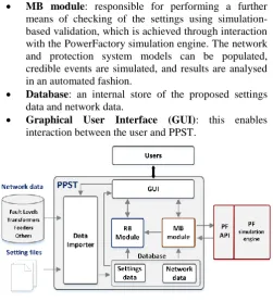
The overall structure of the PPST is illustrated in Fig. 2 and it contains the following main elements:
Data importer: this element imports network data and setting files automatically, and stores this data in an internal database for the use by other elements during the validation process.
RB module: responsible for checking the settings against the rules derived from the setting policies and experts’ knowledge, and automatically analysing simulation results returned from MB module to detect incorrect simulated protection operation.
MB module: responsible for performing a further means of checking of the settings using simulation-based validation, which is achieved through interaction with the PowerFactory simulation engine. The network and protection system models can be populated, credible events are simulated, and results are analysed in an automated fashion.
Database: an internal store of the proposed settings data and network data.
[image:3.595.306.558.83.362.2] Graphical User Interface (GUI): this enables interaction between the user and PPST.
Fig. 2. Overall structure of the PPST
3.2 Validation process
The process of validating protection settings and checking protection performance using PPST is illustrated in Fig. 3:
1) The imported settings data are inserted into the RB module for validation against the rules translated from the setting policies and knowledge of experts. If there are any errors identified in the RB module, the erroneous settings will be highlighted, and suggestions for potential rectification of the errors will be provided, along with the details of the specific rule(s) that the settings violated. Using this information, engineers may amend the setting(s) and repeat the RB validation process. If there are no errors detected, the process will proceed to the MB stage.
2) In the MB validation stage, the PPST will interact with the PowerFactory simulation engine directly. Based on the protection scheme being tested, appropriate equivalent network models are populated; relay models available within PowerFactory are configured using the settings to be validated; and a range of fault events are generated and simulated automatically.
3) The MB simulation results are analysed automatically using the RB module described in step 1 using the dedicated set of rules for analysis of simulation results. This step is used to automatically identify any undesired protection operations in the set of events that have been simulated.
weaknesses in the protection system design, or other “hidden” problems that could be encountered during operation that have not been anticipated or covered by the policy. This would allow the setting policy to be reviewed (manually) with the aid of generated heuristic messages about the identified undesired operation, so that any potential weaknesses can be corrected and the missing scenarios can be added to the policy in the form of new stipulations. When the setting policy are reviewed and improved, the rules for settings validation can be updated (manually) for future validation.
Fig. 3. Overall process of protection settings validation using PPST
3.3 RB validation module
[image:4.595.69.270.227.416.2]The overall architecture of the RB module is illustrated in Fig. 4. The rules are stored in the production memory while the input data (i.e. facts to be reasoned about) are stored in the working memory [20]. There are mainly two types of rules that have been included in the rule base, i.e. the rules for settings validation and for MB results analysis.
Fig. 4. The structure of the RB module
The inference engine at the centre of the process depicted in the figure controls the rule matching and execution process. The pattern matcher (within the inference engine) matches the facts to the relevant rules according to the defined conditions. When the conditions of a rule are fulfilled, the rule will become activated. If multiple rules' conditions are met simultaneously, all of the rules will become activated and the agenda within the inference engine determines the sequence to fire the rules using a conflict resolution strategy, which can
[image:4.595.329.523.529.678.2]be defined by assigning salience values to the rules in their attributes or using the default last-in-first-out order.
Fig. 5. Example rule
An example rule is shown in Fig. 5 to check if the power swing blocking function in the IED is disabled for the feeder distance protection function as required. The rules are stored in text-based files external to the main program and invoked during runtime when needed, thus facilitating the rule maintenance and management.
3.4 MB validation module
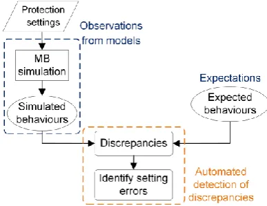
In the MB module, the principle of Model-Based Reasoning (MBR) is adopted for checking of protection performance, which is illustrated in Fig. 6. Protection settings are applied to the IED models (provided by PowerFactory) that are interfaced with the appropriate power network models, and a series of faults are simulated under a wide range of scenarios. The simulated results are referred to as observations, which are compared to expected protection behaviours (referred to as expectations). Any discrepancies between the observations and the expectations indicate the existence of problems in settings or in the design of the protection system, which is clearly important and advantageous to know in advance of actual commissioning and deployment of the protection scheme. The automatic detection of discrepancies is performed using an RB approach, where the information regarding the incorrect operating elements and the nature of the detected problems is also provided.
Fig. 6. The use of MBR for checking protection performance in PPST [21]
[image:4.595.51.284.545.641.2]conditions) which are based on the protection performance requirements (as opposed to setting rules) defined in policies and through experts’ knowledge. User-defined validation schedules are also supported.
The interaction between the MB module and the PowerFactory simulation engine is achieved through the Application Programming Interface (API). More details are available in [21].
4
Demonstration of the PPST
[image:5.595.305.552.147.311.2]This section demonstrates the use of the PPST for validating a distance protection scheme in a transmission network shown in Fig. 7. The protection scheme includes IED 1 and IED 2, and the settings in IED 1 fails to conform with the most up-to-date version of the setting policy are successfully detected by the RB module. Details of the errors and suggestions for amendment of the settings are provided. In the subsequent MB validation stage, additional problems are detected which allow the refinement of the setting policy and update of the rules for future validation.
[image:5.595.43.293.332.491.2]Fig. 7. Test network
Fig. 8 shows the interface for the RB validation of protection settings. On the left hand side, a list of IEDs that are being evaluated is provided. In this example, there are two IEDs within a transmission distance protection scheme being considered. In the middle of the window, a tree view of the settings is provided, where validation results are represented using colour-coded indicators with correct settings in green, warnings in yellow and errors in red. On the right hand side, a summary of the validation results are provided. The bottom of the window shows a list of messages that briefly describe the detected errors.
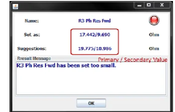
As it can be seen, there are 181 settings in the setting file being assessed in the shown IED, among which 167 settings are considered correct, 3 errors are detected, 11 settings are not validated, and no warnings are identified. The settings not validated are parameters such as CT and VT primary and secondary nominal values, which are not covered by the policies. shows an example of the detailed information about the detected error in the setting of “R3 Ph Res Fwd”. The RB module suggests in this case that the error is caused by inappropriate setting (17.442 Ω) not providing sufficient resistive fault coverage; a suggested setting value (19.775 Ω)
[image:5.595.337.512.411.523.2]calculated by the implemented rules according to the associated requirements specified in the policy is displayed to address this shortcoming
.
The identified erroneous settings are then amended based on the generated messages, and the RB validation is repeated with no errors being are detected.Fig. 8. RB validation of protection settings.
The settings are then forwarded to the MB module for a further simulation-based check of the actual performance under a range of fault scenarios. Fig. 10 shows the user interface of the MB module when the validation process is running. It can be seen that the distance protection zone characteristics are displayed on a complex plane together with the loci of the fault impedance seen by the relay.
Fig. 9. An example of detailed RB validation result
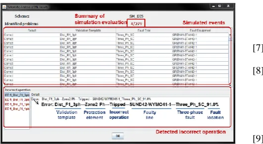
[image:5.595.324.533.557.749.2]During the simulation, an equivalent network model representing the network shown in Fig. 7 is populated in PowerFactory. There are 279 solid fault events applied with 10% steps along all the transmission lines within the network model. The MB module performs automated analysis of protection operation for all of these simulated events as shown in Fig. 11, which indicates that mal-operation is detected in 4 out of 297 simulated cases. The details of the selected mal-operation event are shown in the lower part of the window which provides relevant information including faulty equipment, fault location, mal-operated protection element, etc.
[image:6.595.48.314.390.536.2]In this case, the problem is caused by zone 2 element in IED 1 (in Fig. 7) operates during faults beyond 80% (from the Bus 3 end) of the length of the line between Bus 3 and Bus 4. The reason for this undesired operation is that the setting policy recommends that zone 2 reach should be set to 150% of the protected line impedance, but the line between Bus 3 and Bus 4 happens to be significantly shorter than the protected line, thereby causing an overlap of zone 2 reach of the distance relays on these two lines. Upon close inspection of all four detected incorrect operations, it can be deduced that they are all caused by the same root problem. This allows the refinement of the policy to include additional criteria to cater for unusual length variations of remotely-connected lines in order to avoid such mis-coordination problems in the future.
Fig. 11. Summary of the detected incorrect operations during MB simulation
5
Conclusion
This paper has presented the design of an intelligent system PPST for comprehensive validation of protection settings. The management of protection settings has been reviewed, based on which it has been identified that the most suitable stage of deploying the PPST is the commission and test stage, which is the last line of checking of the exact settings applied to the physical devices. The potential sources of setting errors have been discussed which mainly include manual errors and the potential inadequacy of the setting policy itself.
The design of PPST with both an RB and an MB module has been presented, where the RB module uses rules extracted from setting policy and engineers’ knowledge, while the MB module provides a further means of checking using a simulation-based approach, where protection systems with the
proposed settings are simulated and evaluated in a primary network model environment under a wide range of system events. The entire process can be automated, as discussed. An example demonstrating the operation of PPST has been presented, where the system has successfully detected errors in the RB module and identified additional problems in the subsequent MB module. The future work mainly involves the refinement of the system to fully roll out for industrial application.
References
[1] Siemens, "Global blackouts - lessons learned," 2011. [2] A. Atputharajah and T. K. Saha, "Power system blackouts - literature review," In Industrial and Information Systems (ICIIS), 2009 International Conference on, pp. 460-465.
[3] World Energy Council, "Deciding the Future: Energy Policy Scenarios to 2050," 2007.
[4] J. Sykes, V. Madani, J. Burger, M. Adamiak, and W. Premerlani, "Reliabilty of protection systems (what are the real concerns)," in Protective Relay Engineers, 2010 Annual Conference for, pp. 1-16. [5] CIGRE Working Group B5.31, "Life-time
Management of Relay Settings," 2013.
[6] Q. Hong, S. Blair, C. Booth, V. Catterson, A. Dyśko, and T. Rahman, "Enabling Efficient Engineering Processes and Automated Analysis for Power Protection Systems (Accepted)," Systems Journal, IEEE, 2015.
[7] IEC TC 57, "IEC 61850-1: Introduction and overview," 2003.
[8] K. El-Arroudi, G. Joos, D. McGillis, and R. Brearley, "Comprehensive transmission distance protection settings using an intelligent-based analysis of events and consequences," Power Delivery, IEEE Transactions on, vol. 20, pp. 1817-1824, 2005.
[9] M. Damborg, R. Ramaswami, S. Venkata, and J. Postforoosh, "Computer Aided Transmission Protection System Design Part I: Alcorithms," Power Apparatus and Systems, IEEE Transactions on, vol. PAS-103, pp. 51-59, 1984.
[10] V. Bapeswara Rao and K. Sankara Rao, "Computer aided coordination of directional relays: determination of break points," Power Delivery, IEEE Transactions on, vol. 3, pp. 545-548, 1988. [11] V. Prasad, K. Prakaso Rao, and A. Subba Rao,
"Coordination of directional relays without generating all circuits," Power Delivery, IEEE Transactions on, vol. 6, pp. 584-590, 1991.
[12] H. Abyaneh, M. Al-Dabbagh, H. Karegar, S. Sadeghi, and R. Khan, "A new optimal approach for coordination of overcurrent relays in interconnected power systems," Power Delivery, IEEE Transactions on, vol. 18, pp. 430-435, 2003.
protection scheme with directional overcurrent relays," Power Delivery, IEEE Transactions on, vol. 16, pp. 385-388, 2001.
[14] L. Seung-Jae, C. Myeon-Song, A. Bok-Shin, and Y. Nam-Sun, "A new efficient setting method for protective devices in distribution systems using heuristic rules," in Power Engineering Society Summer Meeting, 2001, pp. 1193-1198 vol.2. [15] C. So and K. Li, "Time coordination method for
power system protection by evolutionary algorithm," Industry Applications, IEEE Transactions on, vol. 36, pp. 1235-1240, 2000.
[16] CAPE. (01/08/2015). Electrocon International , Inc. Available: http://www.electrocon.com/
[17] SIGUARD PSA. (30/03/2015). Protection Security
Assessment. Available:
http://w3.siemens.com/smartgrid/global/en/products-
systems-solutions/control-center-solutions/siguard/pages/siguard-psa.aspx
[18] Operation Technology Inc. (30/07/2015). ETAP. Available: http://etap.com/
[19] DIgSILENT PowerFactory, "DIgSILENT PowerFactory 15 User Manual," 2011.
[19] DIgSILENT PowerFactory, "DIgSILENT PowerFactory 15 User Manual," 2011.
[20] Red Hat Inc. , "JBoss Enterprise BRMS Platform 5 JBoss Rules 5 Reference Guide," 2013.
[21] Q. Hong, C. Booth, V. Catterson, and A. Dyśko, "A Model-based Approach for Automatic Validation of Protection Settings," presented at the PAC World
![Fig. 1. The management of protection settings over the life cycle of the application [5]](https://thumb-us.123doks.com/thumbv2/123dok_us/1529562.105552/2.595.50.280.264.644/fig-management-protection-settings-life-cycle-application.webp)