Impact of Arm Morphology on the
Hydrodynamic Behavior of a Two-arm
Robotic Marine Vehicle
?
Asimina Kazakidi∗ Dimitris P. Tsakiris∗∗ John A. Ekaterinaris∗∗∗
∗Department of Biomedical Engineering, University of Strathclyde,
Glasgow, G4 0NW UK (e-mail: asimina.kazakidi@strath.ac.uk)
∗∗Institute of Computer Science, Foundation for Research &
Technology - Hellas, GR-70013 Greece (e-mail: tsakiris@ics.forth.gr)
∗∗∗Department of Aerospace Engineering, Embry-Riddle Aeronautical
University, Daytona Beach, FL, USA (e-mail: ekaterij@erau.edu)
Abstract: Increasing the functionality and efficiency of small underwater marine robotic systems has been a significant challenge, particularly regarding their use in tasks requiring enhanced maneuverability, long-distance travel and delicate underwater manipulation of objects. In this paper, we explore the impact of bio-inspired arm morphology on underwater propulsion, through examination of the generated hydrodynamic forces and the corresponding complex vortical patterns in the wake of a novel two-arm underwater robotic swimmer, inspired by the octopus arm-swimming behavior. We demonstrate for the first time, via detailed modelling and CFD studies, the use of a variety of slender arm morphologies as thrust actuators in a system that can achieve forward propulsion, by the slow opening and rapid closing of these arms (“arm sculling”), while minimizing the lateral excursion of the system. Robotic prototypes, based on such principles, have already been used by our group to observe marine ecosystems, without disturbing them as much as current ROVs. Further applications of such robotic systems could be envisioned in future medical rehabilitation studies.
Keywords:Unmanned marine vehicles, Marine system identification and modelling, Marine
Robotics, Biologically-Inspired Robots, Computational Fluid Dynamics (CFD)
1. INTRODUCTION
Reduced-size Remotely Operated Vehicles (ROVs) are increasingly being used for important applications of robotics in aquatic environments, like marine ecosystem surveillance, ship-hull maintenance, underwater construc-tion and pipe inspecconstruc-tion, requiring both long-distance op-eration and complex movement scenaria. The performance of such submerged vehicles can be further enhanced by the incorporation of dexterous manipulators, which could per-form demanding and delicate underwater tasks. Although the combination of propulsive and manipulation capabil-ities could potentially offer flexible and efficient robotic solutions in underwater environments, where humans are unable to fully exploit their skills, it presents significant design challenges, which should be thoroughly addressed.
For propulsion in small underwater robotic vehicles, the use of propellers has often proved inefficient, due to the complex rear-end helical vortical-flow structures generated by the propeller blades (Triantafyllou and Triantafyllou, 1995). Devising alternative propulsion mechanisms, for small vehicles, has led to promising technological inno-vations, which increase the generated propulsive force.
? This work was supported in part by the Programmatic Agreements
between Research Centres - GSRT 2015-2017 in the Framework of the Hellenic Republic - Siemens Agreement.
In particular, ideas originating from marine biology, have shown extraordinary potential, like, for example, the use of flapping lateral appendages (Triantafyllou et al., 1993; Conte et al., 2010; Sfakiotakis and Tsakiris, 2009; Sfakio-takis et al., 2016) or pump-jet propulsors (Krueger and Gharib, 2003; Renda et al., 2015).
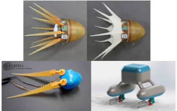
Biological inspiration might prove particularly fruitful also when addressing concurrently the robotic propulsion and object manipulation problems in underwater environ-ments. Within this context, we have been investigating, during the past few years, the development of a family of underwater robotic systems inspired by the extraordinary locomotion and manipulation capabilities of the octopus (Fig. 1) (Sfakiotakis et al., 2015a).
(a) (b)
Fig. 1. Two-arm planar robotic swimmer prototype with rigid arms of two different morphologies: (a) circular cone and (b) circular cone with flaps.
thrust generators on a fixed two-arm planar robotic swim-mer (Figs. 1, 2).
The investigated bilaterally-symmetric planar robotic swimmer contains two arms, positioned symmetrically with respect to a central body (akin to the octopus mantle) and linked to it by actuated rotary joints, addressing the generation of hydrodynamic thrust as a result of the opposite motion of the arms. A rotationally-symmetric 3D swimmer may be obtained by rotating this planar 2-arm system around the longitudinal axis, as presented in Sfakiotakis et al. (2015b). Here, we focus on the effects of one pair of arms moving on the same plane, with the aim to examine the generation of a combined forward thrust.
The novelty of this work lies on the detailed computational investigation, by a high-fidelity immersed-boundary CFD approach (Section 2.3), of the possibility for a planar
arrangement oftwo slender octopus-like arms, moving
ac-cording to a sculling profile (slow opening, followed by fast closing) to achieve propulsion in an aquatic environment, by considering the effect of different arm morphologies and sculling motion parameters on the propulsion char-acteristics and forward hydrodynamic forces generated. This computational work highlights the importance of bio-inspired arm design and extends our previous
CFD-based work on the hydrodynamics of single-arm systems
(Kazakidi et al., 2015b, 2014a, 2012). It is shown that the transition from single- to two-arm systems is favor-able to propulsion, in that it allows minimization of the lateral forces generated and improvement of the obtained propulsive efficiency. Morphologically, several arm designs can be found in nature, from octopus arms and squid tentacles to crab claws, each being distinctive of certain animal behaviors (Kier and Smith, 1985; Sumbre et al., 2001; Grasso, 2008; Full, 2011). The muscular arrange-ment in such arms also differs among animals. An elas-todynamic investigation of single octopus-like arm muscle arrangement and activation has been previously reported in Vavourakis et al. (2014).
The remainder of the paper is organised as follows: Section 2 presents the arm morphologies, arm kinematics and CFD framework. Section 3 discusses the CFD results, in terms of resulting vortical patterns and of hydrodynamic propulsive forces. Section 4 concludes with some final remarks on this work, and discusses possible future directions.
2. COMPUTATIONAL MODELING
2.1 Arm morphology
We consider the underwater robotic swimmer of Fig. 1, which is composed of a central body and a pair of arms, mounted on the rear side of the body via actuated 1-dof rotary joints, whose movement can be prescribed at will. The swimmer is computationally modeled as shown
[image:2.595.347.514.71.169.2]Fig. 2. A two-arm swimmer model for testing the arm morphologies of Figs. 1 and 3—here displayed with the cone arms with flaps (cf. Fig. 3d). Part of the background computational domain is also depicted.
Fig. 3. Top: Arm morphologies considered in the study: (a) Right circular cone (cf. Fig. 1a), (b) Reuleaux triangle, (c) Reuleaux concave, (d) Cone with flaps (cf. Figs. 1b, 2). Power-stroke side view; arrow shows direction of power stroke, in the sculling arm move-ment profile. Bottom line: base-to-tip view (overlaid by surface mesh).
in Fig. 2, with the two arms positioned at the rear of a mantle-like ellipsoid, and at a starting—symmetrical—
angular position of 5◦ with the ellispoid axis (the arms’
base diameter is D, and the ellipsoid’s major and minor
diameters are 5D and 3.25D, respectively, cut at the
rear-side at 75% of its major diameter).
The influence of arm morphology on the hydrodynamic performance of the swimmer is investigated with four dif-ferent arm designs, shown in Fig. 3. The most biologically-related design is inspired by the slender arms of the octo-pus, modeled here as a right circular conical frustum (Fig. 3a), and, hence, is used in this study for comparison with alternative designs and for further computationally para-metric investigations. We, therefore, explore shapes that incorporate small morphological variations (Fig. 3b-c) or extend in dimensions (Fig. 3d). These concept designs have been inspired by cephalopod appendages. Other single-arm morphologies have been previously investigated by CFD studies, including arms with and without octopus-like suckers, and bent arms (Kazakidi et al., 2015b, 2012).
The arm designs of Fig. 3 use as reference scale the base
diameter,D, of the octopus-like conical arm (Fig. 3a) and
[image:2.595.309.527.176.437.2](a) A frustum of a right circular cone with base diameter
D(in theyz−direction, Fig. 3a) and length 10D(taper
ratio of 10:1 in thex−direction).
(b) A frustum of a reuleaux triangle, with circumscribed
circle of the same triangle of diameterD(Fig. 3b) and
length 10D.
(c) A frustum of a modified reuleaux triangle with one side being concave (termed hereafter as “reuleaux con-cave”), with circumscribed circle of the same triangle
of diameterD (Fig. 3c) and length 10D.
(d) A frustum of a right circular cone with base diameter
D, length 10D, and a pair of novel design “flaps”
(described in detail in Sfakiotakis et al. (2015a)), symmetrically positioned at the lateral sides of the
arm’s axis and at an angle of 120◦ between them
(termed hereafter as “cone with flaps”, Fig. 3d).
2.2 Arm kinematics and propulsive efficiency
All arm morphologies were tested with a specificsculling
velocity profile inspired by the octopus arm-swimming motion. The kinematics was abstracted from experimental observations of live octopuses (Kazakidi et al., 2015c), for which the time history was digitized and extracted, demonstrating that sculling is a characteristic and nec-essary ingredient of this particular octopus behavior. Sculling was first introduced in previous robotic stud-ies (Sfakiotakis et al., 2012, 2013, 2014, 2015b), and
in-cludes a relatively slow, low-thrust stroke (termed as
re-covery stroke) and a considerably faster, high-thrust stroke
(termedpower stroke). The corresponding angular velocity
profile can be formulated as follows:
W(t) =
P1(t), 0≤t≤t1; −ω, t1< t≤Tr−t1; P2(t−Tr), Tr−t1< t≤Tr+βt1;
βω, Tr+βt1< t≤Ts−βt1;
P3(t−Ts), Ts−βt1< t≤Ts,
(1)
whereω is the constant angular velocity of the low-thrust
stroke (recovery), βω is the angular velocity of the
high-thrust stroke (power), and β their ratio. The parameters
Aandψare, respectively, the amplitude of arm oscillation
and the corresponding angular position around which each
arm rotates. For W(t) to reach the value of −ω, from
zero, the time t1 = 18Aω is required, whereasTr = 6130Aω is the low-thrust (recovery) stroke duration. The high-thrust
(power) stroke duration isTp =−53β(β2+ 60)t1, and the
total duration, Ts, of the cyclic motion is Ts = Tr+Tp.
The functions P1, P2, P3 are 4th degree polynomials in
time, which ensure C2 continuity for W(t), at all times,
according to:
P1(t) =−2ωrtt1 + 2ωrt
3
t3 1
−ωrt
4
t4 1
, 0≤t≤t1;
P2(t−Tr) = 2ωrt−t1Tr −2ωr
(t−Tr)3
t3 1
−ωr
(t−Tr)4
t4 1
,
Tr−t1< t≤Tr;
P2(t−Tr) = 2ωrt−t1Tr −2ωr3
(t−Tr)3
ω2 pt31
+ω4
r
(t−Tr)4
ω3 pt41
,
Tr< t≤Tr+βt1;
P3(t−Ts) =−2ωrt−t1Ts + 2ω3r
(t−Ts)3
ω2 pt31
+ω4
r
(t−Ts)4
ω3 pt41
,
Ts−βt1< t≤Ts. (2)
2.3 Fluid governing equations and numerical approach
We solve the incompressible Navier-Stokes equations of a Newtonian fluid, formulated as follows:
∂u
∂t + (u· ∇)u=−
1
ρ∇p +ν∇
2u, (3)
∇ ·u=0, (4)
where p is the pressure, ρ is the fluid density, ν is the
kinematic viscosity, andu=[u, v, w] is the velocity vector.
The swimmer model of Fig. 2 is assumed fixed in the laboratory frame, as in experiments where the model is mounted on a force balance, and the arms move according to the sculling profile of equation (1) in quiescent fluid.
For the hydrodynamic simulations, we utilize an Immersed Boundary (IB) numerical approach to approximate the solution of equations (3) and (4), which is based on the curvilinear/immersed boundary (CURVIB) method of Gilmanov and Sotiropoulos (2005); Ge and Sotiropoulos (2007). The IB (fixed-grid) approach was chosen over other body-fitted methods, for its advantage in handling complex geometries and large grid deformations with rela-tively low computational cost, since no moving mesh or re-meshing strategies are required. The method uses a back-ground curvilinear fixed grid to discretize the fluid domain and the two-arm swimmer (immersed body) is considered as a sharp-interface boundary, meshed using unstructured elements (parts of the meshed arms are shown in Fig. 3). Time discretization is performed implicitly with a second-order accurate fractional step method for the time inte-gration of the governing equations. The CURVIB method has been extensively validated and applied to a range of problems (Gilmanov and Sotiropoulos, 2005; Ge and Sotiropoulos, 2007; Borazjani et al., 2008; Borazjani and Sotiropoulos, 2008). For the fluid domain, a 20 million structured cuboid grid was used, extending 30D in both
the x- and z-directions and 15D in the y-direction. A
uniform mesh of size 8D x D x 2D was constructed as
an inner mesh, with an element spacing ofh= 0.02D, to
enclose the arms’ tips at all instances during the cyclic mo-tions. Previous investigations (Kazakidi et al., 2015a) have demonstrated that the resolution provided by this mesh is sufficient to adequately capture the near wall viscous flow and the vortical flow away from the solid surface and the wake. For each of the four arm morphologies examined (numbered as in Fig. 3), the unstructured surface mesh was made of, respectively: (a) 38754, (b) 28776, (c) 28608, and (d) 57338 triangular elements.
3. COMPUTATIONAL FLUID DYNAMIC RESULTS
The two-arm swimmer of Fig. 2 was examined, in terms of hydrodynamic behavior and performance, with mirrored pairs of the arm morphologies of Fig. 3, prescribed to rotate around their bases in mirrored sculling profiles, according to equation (1). For ease of comparison, the profile was used with a single set of sculling parameters
(A= 5◦,ψ= 10◦,ω= 10◦/sec andβ = 3). The
(a) Right circular cone
(b) Reuleaux triangle
(c) Reuleaux concave
[image:4.595.78.519.74.305.2](d) Cone with flaps
Fig. 4. Instantaneous vortical patterns (colored in blue) in the wake of the two-arm swimmer, with the use of various arm morphologies: (a) Right circular conical frustum (cf. Fig. 3a); (b) Reuleaux triangle tum (cf. Fig. 3b); (c) Reuleaux triangle concave frustum (cf. Fig. 3c); (d) Right circular conical frus-tum with side flaps (cf. Fig. 3d). In each line, the left image corresponds to the end of the low-thrust
(recovery) stroke, and the right image to the end of the high-thrust (power) stroke (A = 5◦, ψ =
10◦, ω = 10◦/sec and β = 3). (cf. accompanying videos for (a) and (d) in multimedia material in:
https://www.dropbox.com/sh/ae9spd3uy79khfo/AACUL8VlkNYSLIYG60Qtyo4Wa?dl=0)
rest. Then the arm motion starts and the simulation is completed once a number of cycles is repeated and stable time periodic response has been achieved.
Vortical patterns: For all arm morphologies, when time
periodic response was achieved, the motion resulted in ob-servable flow disturbances in the near-wake region around the arms. For the right circular cone (Fig. 3a) and the reuleaux-type arm designs (Figs. 3b, 3c), two counter-rotating vortical structures were noticeable, originating from the arms’ tips and extending along the trailing side-walls of each of the mirrored arms, for every stroke. As the arms close inwards during the power stroke, each of these vortical structures extends in this direction. Vortical structures generated during a previous sculling period were also visible in the flow field, due to the low diffusion rate in the ambient flow, taking on a horseshoe-like shape (Figs. 4a, 4b, 4c). The above vortical pattern is also evident in the other arm morphology, possibly combined with other vortical structures due to flaps. The cone with flaps (Fig. 3d) induced considerably larger flow disturbances in the near-wake of the two-arm swimmer, for both the recovery and power strokes (Fig. 4d).
Hydrodynamic forces: For all arm morphologies, this
particular mode of propulsion, namely the synchronized sculling movement of the arms in antiphase, produces, for appropriate parameters, considerable propulsive forces. The vortical flow structures are, indeed, indicative of the
propulsive forward thrust T(t) (in the−xdirection),
gen-erated by the two-arm swimmer with the different paired arm morphologies, as depicted in Fig. 5-top. The conical arms with flaps (green line, Fig. 5-top) appear to produce the highest peak thrust (Table 1), while the other three
-20 -10 0 10 20 30 40 50
0 0.5 1 1.5 2 2.5
5 15 25 35
Forward force (mN)
angle (deg)
time (sec) (a) Circular cone
(b) Reuleaux triangle (c) Reuleaux concave (d) Cone with flaps Angular position
-20 -10 0 10 20 30 40 50
0 0.5 1 1.5 2 2.5
5 15 25 35
Lateral force (mN)
angle (deg)
time (sec) (a) Circular cone
[image:4.595.305.560.402.657.2](b) Reuleaux triangle (c) Reuleaux concave (d) Cone with flaps Angular position
Fig. 5. Forward (top) and lateral (bottom) propulsive hy-drodynamic force generated by the two-arm system,
using various arm morphologies (A = 5◦, ψ = 10◦,
ω= 10◦/sec andβ = 3).
-2 0 2 4 6
1 2 3 4
Forward force (mN)
time (sec)
=1 =2 =3
Fig. 6. Influence of β on the forward hydrodynamic force
generated by the paired circular cone arms (A=5◦,
ω=10◦/sec, and ψ=10◦).
Hydrodynamic forces in the lateral (−z) direction of
the paired-arm system (along the xz plane) were also
calculated (shown in Fig. 5-bottom): Both low- and high-thrust arm pairs approximately annul the lateral forces generated by each arm individually, with the high-thrust paired-arm design (namely, the cone with flaps) producing higher drag forces, though still much lower than the forward one.
Effects ofβ andω In Figs. 6 and 7, we further investigate
the influence of the velocity ratio β and angular velocity
ω on the forward hydrodynamic force generated by the
paired circular cone arms (Fig. 3a). Fig. 6 and Table 2 (first three rows) show that, although the peak values of average thrust is similar for all values of the velocity
ratio, β should be greater than 1 in order to produce
propulsive thrust. Fig. 7 shows that increasingω, increases
the average forward propulsive force, achieving high peak force values for the two-arm swimmer (Fig. 7 and last three rows of Table 2). The values of Table 2 are calculated once time periodic response has been reached.
4. CONCLUSIONS
[image:5.595.60.261.71.178.2]The present study addresses arm morphology with respect to the hydrodynamic behavior of a planar two-arm robotic swimmer. It specifically examines the flow development around four different arms with geometries ranging from octopus-like to paddle-like, and estimates the correspond-ing hydrodynamic forces. Of these morphologies, the cir-cular cone generated relatively little forward force, while the arms with flaps considerably larger. However, thrust
Table 1.
Peak and average hydrodynamic forces on four paired
arm morphologies (A=5◦,ψ=10◦, ω=10◦/sec,β=3)
Av. forward Peak Av. lateral
force (mN) force (mN) force (mN)
Circular cone 0.0316 5.7978 -0.0006
Reuleaux triangle 0.0706 4.1653 -0.0311
Reuleaux concave 0.1239 4.5174 -0.0229
Cone with flaps 0.5983 32.1621 -0.0496
Table 2.
Peak & average forces on the paired circular cone arms
(Fig. 3a) for various β andω values (A=5◦,ψ=10◦)
β ω Av. forward Peak Av. lateral
(◦/sec) force (mN) force (mN) force (mN)
β = 1 ω= 10 -0.0131 5.7046 -0.0013
β = 2 ω= 10 0.0047 5.7888 -0.0010
β = 3 ω= 10 0.0316 5.7978 -0.0006
β = 3 ω= 20 0.1170 22.8657 0.0008
β = 3 ω= 30 0.1862 50.8314 0.0017
-20 -10 0 10 20 30 40 50
0 0.5 1
Forward force (mN)
time (sec)
=10o/s =20o/s
=30o/s
Fig. 7. Influence ofω on the forward hydrodynamic force
generated by the paired circular cone arms (A= 5◦,
ψ= 10◦, andβ= 3).
production may not necessarily mean greater efficiency of the system and further investigation is required. For all geometries, the lateral forces of the two arms almost cancel out.
This study also demonstrates that for propulsion to be
achieved with the two-arm system, the parameterβ must
be larger than 1, corresponding to a sculling arm motion profile with unequal power and recovery stroke velocities. The CFD studies can assess such propulsive force measure-ments adequately well, when compared with experimeasure-ments (Sfakiotakis et al., 2015a), enabling the use of these models to other multi-arm swimmers (Fig. 8).
[image:5.595.322.525.72.179.2]Future studies will include the investigation of more arm designs and kinematic parameters, in an attempt to opti-mise this type of robotic systems, based on force generation and efficiency. Another future extension of these studies is envisaged to target human robotic appendages that could be utilised in medical prosthetics and orthotics to provide, for example, swimming capabilities and support to rehabilitation patients.
Fig. 8. Top row: Eight-arm robotic prototypes: Actua-tion of compliant arms is performed via dedicated microservomotors (Sfakiotakis et al., 2015b). Bottom row: polyurethane-made arms of conical morphology tested on a two-arm robotic system (Kazakidi et al., 2014b) and a CAD schematic of a robot using the arms with flaps (Sfakiotakis et al., 2015a).
ACKNOWLEDGEMENTS
[image:5.595.341.521.463.576.2]REFERENCES
Borazjani, I., Ge, L., and Sotiropoulos, F. (2008). Curvi-linear immersed boundary method for simulating fluid
structure interaction with complex 3d rigid bodies. J
Comput Phys, 227, 7587–7620.
Borazjani, I. and Sotiropoulos, F. (2008). Numerical inves-tigation of the hydrodynamics of carangiform swimming
in the transitional and inertial flow regimes. J Exp Biol,
211, 1541–1558.
Boyer, F. and Porez, M. (2014). Multibody system
dynamics for bio-inspired locomotion: from geometric
structures to computational aspects. Bioinsp. Biomim.,
10, 025007.
Boyer, F., Porez, M., and Leroyer, A. (2010). Poincar´´
e-cosserat equations for the lighthill three-dimensional large amplitude elongated body theory: application to
robotics. J. Nonlinear Sci., 20, 47–79.
Conte, J., Modarres-Sadeghi, Y., Watts, M., Hover, F., and Triantafyllou, M. (2010). A fast-starting robotic
fish that accelerates at 40ms−2. Bioinsp Biomim, 5,
035004.
Ekeberg, ¨O. (1993). A combined neuronal and mechanical
model of fish swimming. Biol Cybern, 69(5-6), 363–74.
Full, R. (2011). Invertebrate locomotor systems. Compr
Physiol, Suppl 30 Handbook of Physiology, 853–930. Ge, L. and Sotiropoulos, F. (2007). A numerical method
for solving the 3d unsteady incompressible navier–stokes equations in curvilinear domains with complex
im-mersed boundaries. J Comput Phys, 225, 1782–1809.
Gilmanov, A. and Sotiropoulos, F. (2005). A hybrid
cartesian/immersed boundary method for simulating flows with 3d, geometrically complex, moving bodies. J Comp Phys, 207, 457–492.
Grasso, F. (2008). Octopus sucker-arm coordination in
grasping and manipulation. Am Malac Bull, 24, 13–23.
Ijspeert, A. (2001). A connectionist central pattern gener-ator for the aquatic and terrestrial gaits of a simulated
salamander. Biol Cybern, 85(5), 331–348.
Kanso, E. (2009). Swimming due to transverse shape
deformations. J. Fluid Mech., 631, 127–148.
Kazakidi, A., D. P. Tsakiris, Sotiropoulos, F., and Eka-terinaris, J.A. (2014a). A computational fluid dynamic
study of intense cephalopod-like motions. In44th AIAA
Fluid Dynan Conf, 1–15. Atlanta, USA.
Kazakidi, A., Gnanamanickam, E., Tsakiris, D., and Eka-terinaris, J. (2014b). A flow visualization study of single-arm sculling movement emulating cephalopod thrust
generation. In 67th Ann Meet APS Div Fluid Dynam.
San Francisco, USA.
Kazakidi, A., Tsakiris, D.P., Angelidis, D., Sotiropoulos,
F., and Ekaterinaris, J.A. (2015a). CFD study of
aquatic thrust generation by an octopus-like arm under
prescribed deformations. Comput & Fluids, 115, 54–65.
Kazakidi, A., Vavourakis, V., Pateromichelakis, N.,
Eka-terinaris, J.A., and Tsakiris, D.P. (2012).
Hydrody-namic analysis of octopus-like robotic arms. IEEE Int
Conf Rob Autom (ICRA), 5295–5300. St. Paul, USA. Kazakidi, A., Vavourakis, V., Tsakiris, D.P., and
Ekateri-naris, J. (2015b). A numerical investigation of flow
around octopus-like arms: near-wake vortex patterns
and force development. Comp Meth Biomech Biomed
Eng, 18(12), 1321–1339.
Kazakidi, A., Zabulis, X., and Tsakiris, D.P. (2015c). Vision-based 3d motion reconstruction of octopus arm swimming and comparison with an 8-arm underwater
robot. In IEEE Int Conf Rob Autom (ICRA), 1178–
1183. Seattle, WA, USA.
Kier, W. and Smith, K. (1985). Tongues, tentacles and trunks: the biomechanics of movement in
muscular-hydrostats. Zool J Linn Soc, 83, 307–324.
Krueger, P. and Gharib, M. (2003). The significance of vortex ring formation to the impulse and thrust of a
starting jet. Physics of Fluids, 15(5), 1271–1281.
LaSpina, G., Sfakiotakis, M., Tsakiris, D., Menciassi, A., and Dario, P. (2007). Polychaete-like undulatory robotic
locomotion in unstructured substrates. IEEE
Transac-tions on Robotics, 23(6), 1200–1212.
McIsaac, K.A. and Ostrowski, J.P. (2002). Experimental verification of open-loop control for an underwater
eel-like robot. Int J Rob Res, 21, 849–860.
Renda, F., Giorgio-Serchi, F., Boyer, F., and Laschi, C. (2015). Structural dynamics of a pulsed-jet propulsion
system for underwater soft robot. Adv Rob Sys, 12, 68.
Sfakiotakis, M., Chatzidaki, A., Evdaimon, T., Kazakidi, A., and Tsakiris, D.P. (2016). The role of compliance
in pedundulatory locomotion. 24th Med Conf Control
Autom (MED16), 532–538.
Sfakiotakis, M., Kazakidi, A., Chatzidaki, A., Evdaimon, T., and Tsakiris, D.P. (2014). Multi-arm robotic
swim-ming with octopus-inspired compliant web. InInt Conf
Int Rob Syst (IROS), 302–308. Chicago, Illinois, USA. Sfakiotakis, M., Kazakidi, A., Evdaimon, T., Chatzidaki,
A., and Tsakiris, D.P. (2015a). Multi-arm robotic
swim-mer actuated by antagonistic SMA springs. IEEE/RSJ
Int. Conf. Int. Rob. Syst. (IROS), 1540–1545. Germany. Sfakiotakis, M., Kazakidi, A., Pateromichelakis, N., Eka-terinaris, J.A., and Tsakiris, D.P. (2012). Robotic un-derwater propulsion inspired by the octopus multi-arm
swimming. InIEEE Int Conf Rob Autom (ICRA), 3833–
3839. St. Paul, USA.
Sfakiotakis, M., Kazakidi, A., Pateromichelakis, N., and Tsakiris, D.P. (2013). Octopus-inspired 8-arm robotic
swimming by sculling movements. In IEEE Int Conf
Rob Autom (ICRA), 5135–5141. Karlsruhe, Germany. Sfakiotakis, M., Kazakidi, A., and Tsakiris, D.P. (2015b).
Octopus-inspired multi-arm robotic swimming. Bioinsp
Biomim, 10(3), 035005.
Sfakiotakis, M. and Tsakiris, D.P. (2009). Undulatory
and pedundulatory robotic locomotion via direct and
retrograde body waves. IEEE ICRA, 3457–3463.
Sfakiotakis, M. and Tsakiris, D. (2007). Biomimetic
centering for undulatory robots.J Rob Res, 26, 1267–82.
Sumbre, G., Gutfreund, Y., Fiorito, G., Flash, T., and Hochner, B. (2001). Control of octopus arm extension
by a peripheral motor program. Science, 293, 1845–48.
Triantafyllou, G., Triantafyllou, M., and Grosenbaugh, M. (1993). Optimal thrust development in oscillating foils
with application to fish propulsion.J Fluids Struct, 7(2),
205–224.
Triantafyllou, M. and Triantafyllou, G. (1995). An efficient
swimming machine. Scientific American, 40–48.
Vavourakis, V., Kazakidi, A., Tsakiris, D.P., and Ekateri-naris, J.A. (2014). A nonlinear dynamic finite element
approach for simulating muscular hydrostats. Comput