Numerical Modeling and Simulation of Supersonic
Flows in Propulsion Systems by Open-Source Solvers
Jimmy-John O.E. Hoste,
∗Vincent Casseau,
∗Marco Fossati
† Centre for Future Air-Space Transportation Technology,Department of Mechanical and Aerospace Engineering,
University of Strathclyde, Glasgow, G1 1XJ, United Kingdom
and
Ian J. Taylor
‡Division of Aerospace Sciences, School of Engineering,
University of Glasgow, Glasgow, G12 8QQ, United Kingdom
and
Rowan J. Gollan
†Centre for Hypersonics, School of Mechanical & Mining Engineering,
The University of Queensland, Brisbane, QLD 4072, Australia
Two open-source solvers, Eilmer and hyFoam, are here considered for their performance in simulating high-speed flows in different flow conditions and geometric configurations typical of propulsive systems at supersonic speeds. The goal is to identify the open-source platform providing the best compromise between accuracy, flexibility and computational cost to eventually simulate the flow fields inside ramjet and scramjet engines. The differ-ences in terms of discretization and solution methods of the selected solvers are discussed in terms of their impact on solution accuracy and computational efficiency and in view of the aerothermodynamic analysis and design of future trans-atmospheric propulsive systems. In this work steady state problems are considered. Numerical results of two scramjet type engines demonstrated a similar predictive capability of both codes in non-reacting condi-tions. These results highlight their potential to be considered for further characterization of overall engine performance.
Nomenclature
ρ density (kg/m3)
ui velocity components (m/s)
δij kronecker delta: 0 (i6=j), 1 (i=j)
p static pressure (P a)
τij molecular stress tensor ¯
ρug00iu00j Reynolds stress tensor
E total energy (J/kg)
H total enthalpy (J/kg)
I turbulence intensity (%)
qj heat flux components (W/m2) Ys mass fraction of speciess T static temperature (K)
Xs molar fraction of speciess µs species dynamic viscosity (P a.s)
κs species thermal conductivity (W/(m2K))
k turbulent kinetic energy (J/kg)
ω dissipation rate of turbulent kinetic energy (1/s)
µt/µ ratio of turbulent to laminar viscosity
∗PhD Candidate, AIAA Student Member. †Lecturer, AIAA Member .
I.
Introduction
The future of access-to-space systems is faced with many technical and economic challenges. Re-usability has become a main paradigm in the aerospace and space industry as exemplified by the recent Falcon 9 program of SpaceX and the constraints imposed by such requirements further increase the complexity of the design process. Over the years different design solutions have been proposed to realize reliable and cost-effective systems. Canonical solutions for access-to-space systems based on two-, or multi-stage-to-orbit designs improved efficiency while allowing for some degree of re-usability.1, 2 The technology of combined
cycle propulsion (CCP) systems has allowed switching between different propulsion technologies in a way to ensure the most efficient flight path as exemplified by Marquardt’s conceptual design of the Supercharged Ejector RamJet (SERJ) engine.3 A recent study conducted by NASA showed how rocket-based combined cycle (RBCC) and turbine-based combined cycle (TBCC) engines are technologies that could enable highly-efficient access to space and future airliner propulsion systems preserving full re-usability.4
The concept of combining together different propulsive systems to optimize the performance according to the operational regime is key to the development of future vehicles. Along this perspective, engineering op-timized systems for the atmospheric high-Mach segment of the flight path is crucial. Ramjet and supersonic combustion ramjet (scramjet) technologies are constantly being studied to target specifically the supersonic and hypersonic regimes thanks to their favourable specific impulse at high Mach numbers. Designing and testing such advanced systems demands the ability to fully control the complex flow physics of these sys-tems. Computational Fluid Dynamics (CFD) and experimental testing have seen great advances through the years in terms of reliability and accuracy. However, in the case of supersonic and hypersonic regimes, realistic high-enthalpy conditions can only be maintained and thus measured in experimental facilities for a very short time, in the order of milliseconds,5, 6 and the numerical approach still remains as the primary
analysis tool to cover the operating regimes of scramjets in a consistent manner. CFD methods targeting the solution of the flow field inside supersonic engines are faced with the challenges to address internal flows dominated by complex shock wave patterns, shock-wave boundary layer interaction (SWBLI), separation and most importantly supersonic combustion which, in many cases, is characterized by finite rate chemistry. Inaccurate predictions of shock positions and separation locations can lead to unreliable results when reac-tions are activated putting at risk the success of the entire design process.
A variety of CFD solvers are present in the literature for the simulation of high-speed air-breathing en-gines. These include REACTMB,7, 8 WIND-US,9, 10 TAU-code,11 VULCAN12, 13 and the recent SU2.14, 15
OpenFOAM16is a well-established open platform in the scientific community. Supersonic combustion studies
with OpenFOAM-based solvers include the work of Chapuis,17Fureby,18 Dr¨oske19 and Makowka.20
Unfor-tunately the latter OpenFOAM implementations are not yet fully open-source. The OpenFOAM-based hyFoamaand its variant with a two-temperature model hy2Foam,21, 22 are solvers developed at the
Univer-sity of Strathclyde with the purpose of studying external aerodynamics in re-entry flows around vehicles characterized by high-temperatures effects.
An interesting recent open-source software targeting specifically compressible and potentially chemically reacting flow is Eilmerb. It is a solver developed at the University of Queensland. Gollan and Jacobs23 discussed the main features of Eilmer and validated the solver with several test cases. Chan et al.24 pre-sented the validation of the implemented k-ωmodel in Eilmer with test cases representative for parts of the flow fields inside scramjet engines. Other studies with Eilmer for non-reacting conditions include supersonic cavity flows,25, 26 hypersonic SWBLI27 and scramjet combustors.28 In reacting conditions the solver has
been used for combustion in narrow channels by Kang et al.29
This work represents a first step towards the formulation and implementation of an open-source simu-lation platform for supersonic and hypersonic propulsion systems where high-fidelity CFD approaches will be coupled with a mission profile analyzer/optimizer to accurately explore the behavior of the propulsion system over a wide range of operating and environmental conditions. Along this perspective, the choice of the most suitable open-source CFD solver that balances accuracy and computational cost is an important
factor. The present work presents a comparative assessment of hyFoam and Eilmer for internal supersonic flows to help identify those characteristics of the flow solvers needed to efficiently realize further develop-ments in the open-source simulation framework. As a preliminary step towards this objective, this work will be focusing only on steady state problems.
The material is presented as follows. Section II describes the governing equations for fluid flows followed by the main differences between the two solvers. Eventually a series of the test cases will be discussed in Section III including proper validation with available reference data. This section will also include results and finally conclusions and future work are detailed in Section IV.
II.
Physical Modelling and Numerical Approaches
The aim of this work is to assess the predictive capability of Eilmer and hyFoam for scramjet type geometries with a main focus on the accuracy. Results will be influenced by the choice of the discretization schemes and by the models adopted for the different terms appearing in the system of conservation equations.
II.A. Governing Equations
The flow established in scramjets is addressed by means of the Navier-Stokes augmented with the conservation equations for each chemical species that constitutes the air-fuel mixture
∂ρ¯
∂t + ∂
∂xi( ¯ρu˜i) = 0 (1)
∂
∂t( ¯ρu˜i) + ∂ ∂xj
( ¯ρu˜ju˜i+δijp¯) = ∂ ∂xj
¯
τij−ρ¯ug00
iu 00 j (2) ∂ ∂t ¯
ρE˜+ ∂
∂xj
¯
ρuj˜ H˜= ∂
∂xj
¯
τijui˜ +τiju00i −qj¯ −ρ¯Hg00u00j
(3)
∂( ¯ρY˜s) ∂t +
∂( ¯ρY˜su˜j) ∂xj =−
∂ ∂xj
¯
ρYgs00u00
j
(4) where ¯ρ, ¯ρuj˜ , ¯ρE˜, ¯ρYs˜ are respectively density, momentum, total energy per unit volume and partial den-sities of the speciess(s=1,. . .,N). The symbols ¯xand ˜xrepresent respectively the time and Favre average. Equations 1 to 4 are written in such a way that those terms which require modeling are indicated at the right-hand side. The system of conservation equations for a turbulent chemically reacting flow needs exten-sive modeling. A comprehenexten-sive overview of the modeling practice for supersonic internal flows can be found in the work of Baurle and the interested reader is referred to the literature.30 In the following paragraphs the main differences in such modeling between the selected solver will be addressed.
II.B. Eilmer and hyFoam: physical and numerical modeling
Thermochemistry A thermally perfect gas is usually assumed in ramjet and scramjet flows where the
heat capacities are temperature dependent. In hyFoam the species heat capacities are obtained by adding the contributions of the different energy modes.21 The same is applied for the total energy. Eilmer31 adopts
temperature dependent species heat capacities and energies that are evaluated with the polynomial curve fits of McBride and Gordon.32 The polynomials rely on coefficients that are species dependent and for this
purpose the CEA232 library from NASA is used. Given the relatively low temperatures in the targeted applications, the different approach is not expected to greatly impact the flow predictions.
Transport properties The viscosity µs and thermal conductivity κs of each species is temperature
dependent. In both hyFoam and Eilmer, CEA2 curve fits are used.32 For the mixture values the former
Turbulence model In scramjet flows SWBLI are important features and the turbulence model will play a major role in dealing with it. The linear eddy viscosity two-equation k−ω turbulence model is the base model for both solvers even if a different variant of it is implemented, and thus available, in each one of them. Eilmer uses Wilcox’s 2006 k−ω model24, 34 while hyFoam adopts Menter’s Shear Stress
Transport (SST) variant.35–37 The two-equation models approach is commonly adopted for hypersonic
propulsion CFD.38 This trend follows from the larger range of applicability and suitability for complex
geometries in comparison to e.g. one equation models without drastically increasing the computational cost.30 The development of the SST model was motivated by the sensitivity of the k-ω model to freestream
turbulence properties. Away from walls the model uses a k- turbulence formulation and switches to k-ω
when approaching physical boundaries. In a SWBLI study reported by Georgiadis et al.38 the SST model
had a tendency to overpredict the flow separation when comparing with experimental PIV data and other turbulence models (no comparison with 2006 k-ω). Over the years the freestream sensitivity limitation of the k-ω has been addressed and improvements have been made. The improvements in the 2006 version implemented in Eilmer include: reduced freestream sensitivity, improved behavior for compression corners and hypersonic SWBLI and the capability to handle free shear flows.34 For this latter model the importance of the stress limiter parameter in predicting separation was demonstrated by Wilcox34 and confirmed by Chan et al.24 and reasonable agreement with wall pressure data was observed. This version is capable
of similar performances as Menter’s SST model and the effect of the choice in each solver will be closely observed in the comparison test cases with special attention to separation in SWBLI regions.
The Finite Volume Discretization Both solvers adopt a Finite Volume discretization for the govern-ing equations where the inviscid and viscous fluxes are treated separately. The main difference between Eilmer and hyFoam is observed in the evaluation of the inviscid fluxes. In Eilmer the inviscid fluxes are obtained with a so-called adaptive method which switches between the Equilibrium Flux Method (EFM) and an Advection Upstream Splitting Method combining difference and vector splitting (AUSMDV). The EFM method39is used in the vicinity of shock waves and being derived from the kinetic theory is inherently
upwind which makes it suitable for highly compressible flows. In the other regions Wada and Liou’s40
AUS-MDV method is preferred due to its less dissipative character. The AUSM-family schemes have received much attention in the CFD community thanks to the wide range of applicability from low to high Mach number and to multiphase flows.41 In a comparison study by Coratekin et al.42 the authors observed a
better performance of the AUSMDV scheme in hypersonic flow conditions compared to the original AUSM scheme and Roe’s flux difference splitting scheme. Eilmer uses explicit time-stepping on structured grids. The hyFoam is an unstructured solver developed in OpenFOAM 2.3 originating from two available solvers: rhoCentralFoam and reactingFoam. This latter is a combustion solver that has multi-species libraries while rhoCentralFoam is a single-species density-based compressible solver which makes use of the central-upwind schemes of Kurganov and Tadmor.43, 44 The use of these flux schemes for propulsive supersonic flow prob-lems has not yet been thoroughly evaluated. The motivation of Kurganov and Tadmor43, 44 in introducing a central scheme lies in the fact that the method does not rely on the specific eigenstructure of the prob-lem. The central-upwind character follows from the calculation of a weighting coefficient that uses one-sided local speeds of propagation. Greenshield et al.45 implemented the method within OpenFOAM and similar
predictions to a Roe solver were obtained for the separation region on a hypersonic flow over a double cone configuration. The implementation combines an explicit predictor step for the convection of the conserved variables followed by an implicit corrector step for the diffusion of primitive variables.
are the structured and the explicit character of the code. Unstructured grids allow more complex geometries to be simulated and can become a necessity when Rectangular-to-Elliptic-Shape-Transition scramjet28types are considered. Explicit solvers are known to increase the computational cost in steady state problems. A new version of the Eilmer codec46 is currently being developed which will address both limitations. This
study will do a thorough investigation of the above introduced numerics and model choices for the flows of interest on Cartesian grids.
III.
Test Cases
Results refer to two test cases available in the literature for typical propulsive applications: the first is from Lorrain6 and the second is from Smayda et al.47 All simulations have been made considering the same
grid for the different solvers, thus allowing a grid-independent comparison.
III..1. Lorrain’s Scramjet
The scramjet’s internal flow is dominated by shock wave reflections interacting with boundary layers. This test case asses the capability of both CFD solvers in predicting a shock train and allows evaluation of the numerical diffusion of the spatial discretization schemes. The selected scramjet geometry is a test case investigated by Lorrain et al.6, 48 in the University of Queensland’s T4 hypersonic piston-driven shock tunnel. It is a specific type of scramjet engine which relies on the concept of radical farming and has been introduced within the the SCRAMSPACE I project.49 The same geometry has previously been simulated
with OpenFOAM 2.1 d by Mogavero et al.50 using the Weighted Average State (WAS) method.51 Since
the development of this solver called rhoFoam, OpenFOAM has had major changes in the thermophysical modeling.
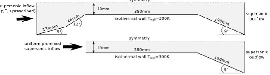
Problem formulation Figure 1 shows the geometry and boundary conditions used by Lorrain et al.6 for study of the finite-rate chemistry mechanisms governing the combustion process with CFD++.52 As it can be seen in the upper representation, the full geometry consists of an inlet (sharp leading edge) with two ramps leading to the constant area combustor which terminates in an exit nozzle. As a numerical demonstration, a premixed configuration (lower representation) was also studied. Lorrain aimed at investigating shock and expansion wave structures as well as boundary layer viscous heating effects. The test case has been simulated in three different conditions6
a. A full geometry (upper part of Figure 1) with only air as a working fluid.
[image:5.612.87.535.520.645.2]b. A frozen hydrogen fueled simulation with only the combustor and nozzle (lower part of Figure 1). c. A reacting hydrogen fueled simulation with only the combustor and nozzle (lower part of Figure 1).
Figure 1: The geometry considered for scramjet CFD simulations6 with top: for fuel-off case, bottom: for
The mesh grading used in the presented simulations ensured ay+value smaller than unity. In the fuel-off test case the number of cells in the first intake, second intake, combustor and nozzle were respectively equal to 110 ×456, 110×300, 110×1454 and 110 ×718 resulting in a total of 322,080 cells with a maximum aspect ratio of 340. For the frozen and combusting simulations the mesh size was reduced to 133,414 cells with a maximum aspect ratio of 501 to enable a quicker analysis. From the final report of Lorrain53 (Table
7.1 without symmetry assumption) the grid sizes selected in the current study are considered to be adequate. Table 1 summarizes the flow conditions of Lorrain’s experimental and numerical study for the fuel-off case with u, p, T and X being respectively the velocity, static pressure, static temperature and mole fractions. Turbulent inlet quantities were set with an intensity I of 2 % and a ratio of viscosities µt/µ equal to 5. A thermally perfect gas is assumed with heat capacities depending on the temperature. The symmetry of the geometry was exploited in the simulations and the walls are considered isothermal at a temperature of 300 K. This assumption is acceptable considering the very short experimental test time, on the order of milliseconds, which is not sufficient to cause significant temperature elevations. A turbulent Prandtl number of 0.89 was specified in both solvers for the presented results.
Table 1: Flow conditions at the inlet of the scramjet geometry for the different simulations.6
u (m/s) p (Pa) T (K) XO2(−) XN2(−) XH2(−) fuel-off 2830 4100 370 0.21 0.79 0.0 frozen / reacting u(y) p(y) T(y) 0.157 0.593 0.25
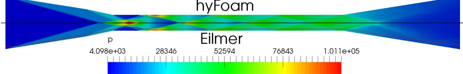
Results Firstly results have been obtained for test case “a”, a set-up with only the presence of air. The
[image:6.612.71.540.372.447.2]pressure contour plot in Figure 2 shows a very similar predictive capability between both solvers.
Figure 2: The contour plot of pressure shows a similar shock structure inside the geometry between hyFoam and Eilmer
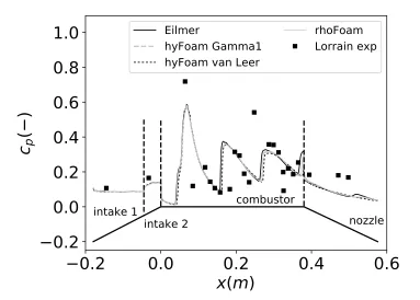
In order to better distinguish the results from both codes, the wall pressure coefficient is presented in Figure 3 with the experimental data of Lorrain et al.6 CFD solution from rhoFoam50 is displayed as well
diagram (NVD) schemes while van Leer is a total variation diminishing (TVD) scheme. The setting Gamma1 in hyFoam is the upper limit of this scheme characterized by more numerical diffusion and this is thought to be the explanation of a smoother pressure profile compared to van Leer. On the other hand, results did not differ much except near the end of the combustor with a much shorter and later pressure peak prediction.
0.2
0.0
0.2
0.4
0.6
x(m)
0.2
0.0
0.2
0.4
0.6
0.8
1.0
c
p
(
)
intake 1
intake 2
combustor
nozzle
Eilmer
hyFoam Gamma1
hyFoam van Leer
[image:7.612.117.500.124.398.2]rhoFoam
Lorrain exp
Figure 3: Wall pressure profiles for the fuel-off test case, comparison with experimental values At the end of the nozzle (Figure 3) a weak shock reflection is captured by Eilmer and hyFoam (more pronounced for the former solver) which is barely seen in rhoFoam. The reason could be the use of a different mesh in the latter solver. A closer look at the physics in the region near the combustor entrance explains the onset of the difference in positions between Eilmer and hyFoam discussed above. Figure 5 shows the presence of a shock induced boundary layer separation bubble which was also observed by Lorrain.53 The hyFoam results are obtained with the Gamma1 limiter which gave the most satisfactory wall pressure profile and non-oscillatory behavior. The location of the separation region slightly differs (≈3.5mm) as well as the size. This latter behavior in hyFoam is expected as the k−ω SST model tends to overpredict the size of SWBLI regions as pointed out by Georgiadis et al.38 In terms of turbulent kinetic energy, Eilmer does predict
higher values in this region. More detailed experimental data is required in the separation region to evaluate the prediction by Wilcox 2006 k-ω model but, in accordance with other observations of similar flows,38 a
accounted for in the present simulations, hence explaining partly the mismatch between experimental data and CFD. From the fuel-off analysis, no conclusion can be drawn on the better performance in accuracy of one solver over the other.
0.1
0.2
0.3
0.4
x(m)
0.0
0.1
0.2
0.3
0.4
0.5
0.6
0.7
c
p
(
)
intake 1
intake 2
combustor
nozzle
Eilmer
hyFoam Gamma1
hyFoam van Leer
rhoFoam
[image:8.612.119.499.111.380.2]Lorrain exp
Figure 4: Combustor wall pressure close-up view as predicted by hyFoam and Eilmer
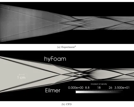
[image:8.612.78.533.446.621.2](a) Experiment6
[image:9.612.72.540.47.422.2](b) CFD
Figure 6: A comparison of the experimental Schlieren and CFD for the fuel-off conditions. Note that the scales do not perfectly match.
For the simulations in frozen conditions the profiles of the flow variables at the entrance of the combustor are extracted from the fuel-off results and prescribed as inlet boundary conditions. In order to account for the presence of hydrogen the pressure profile was altered aspf rozen=pf uel−of f/(1−XH2). Figure 7 shows the inlet profiles of temperature and velocity on the left and right side respectively. A symmetry plane is at the top and the wall at the bottom. The velocity is very similar between both solvers but the temperature shows a significant increase in peak value in the boundary layer for hyFoam. A similar behavior is observed for turbulent kinetic energy. The difference seems to be a consequence of the turbulence model. For the frozen condition CFD data of pressure is available from Lorrain et al.6 and Mogavero et al.50 along a
0 500 1000 1500 2000 2500
u (m/s)
1.0
0.5
0.0
y (cm)
velocity
Eilmer
hyFoam
400 600 800 1000 1200 1400
T (K)
[image:10.612.115.495.60.327.2]temperature
Figure 7: Temperature and velocity profiles at the entrance of the combustor for Eilmer and hyFoam.
0.0
0.2
0.4
0.6
x (m)
0
25
50
75
100
p (kPa)
combustor
nozzle
Lorrain CFD
rhoFoam
hyFoam van Leer
Eilmer
[image:10.612.116.498.370.643.2]Enterprise in the West of Scotland) High Performance Computer.55 The run used 48 Intel Xeon X5650 2.66 GHz cores (Santa Clara, CA, USA) with 48 GB RAM and 4xQDR Infiniband Interconnect computer-networking communications. The hyFoam reached 10,000 iterations after a wall-clock time of 1396 sec. In Eilmer it took 2700 sec to perform the same number of iterations. The advantage of working with a combination of explicit and implicit schemes in hyFoam is demonstrated. The new version of Eilmer will address this current limitation. It must be noted that conclusions on convergence speed and grid requirements cannot be drawn based on the studies in this work.
III..2. Hypervelocity Dual-Mode Scramjet
Another type of scramjet flow has been selected for the comparison of both codes. The scramjet design is a dual-mode scramjet and has been studied experimentally by Smayda et al.47 in NASA’s HyPulse facility. Their interest focused in the higher velocity regimes where pure scram-mode was expected also referred to as hypervelocity (above Mach 7 flight enthalpy conditions). Vogel56 performed the CFD simulations with
REACTMB, North Carolina State University’s in-house solver, to compare with the experiments. The fol-lowing numerical study considers pure scram-mode.
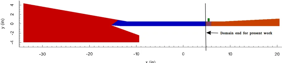
Problem formulation Figure 9 shows a side view of the dual-mode scramjet geometry. The geometry is inspired by the University of Virginia direct-connect Dual Mode Scramjet (DSMJ). The inlet section (red) consists of a forebody wedge and inlet cowl redirecting the flow to a constant area rectangular isolator section (blue + purple). Following this shock train section, the flow enters the combustor and is accelerated through the exit nozzle (orange) after fuel injection (green). As the present study focuses on two-dimensional simu-lations only the inlet (red) and isolator (blue) regions are considered. Near the entrance of the combustor chamber (purple) three-dimensionality becomes important. Vogel56 simulated the test case at equivalent
[image:11.612.79.532.385.487.2]flight conditions of Mach 7 and 10 with a dynamic pressure of 47.88 kPa (1000 psf).
Figure 9: The dual-mode scramjet geometry studied in NASA’s HyPulse facility.47, 56
The geometry and mesh configuration used in the present numerical study with Eilmer and hyFoam are given in Figure 10. The mesh contained 594,000 cells with a maximum aspect ratio of 722. Grading towards the walls ensured y+ values lower than unity. The Mach 7 equivalent flight test conditions are recreated in this work. A 0.93 degrees angle of attack was considered in the simulations56 yielding two velocity components as given in Table 2. Freestream turbulence levels were set to 5 % and 10 for I and
µt/µ, respectively. The walls are considered isothermal at 300 K. Just like in Lorrain’s test case, the limited
test time did not allow for significant heating of the geometry. Turbulent Prandtl number was set to 0.89 in both solvers.
Table 2: Flow conditions at the inlet of the dual-mode scramjet geometry for Mach 7 equivalent flight simulations.56
Figure 10: Geometry and boundary conditions for the numerical study of the dual-mode scramjet. Each 4th line is represented in every direction for clarity.
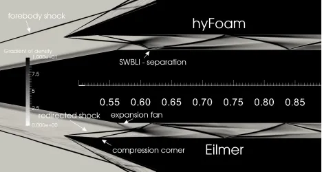
[image:12.612.73.541.356.606.2]Results Figure 11 presents the gradients of density as predicted by both solvers. More complex shock wave interactions are present at the entrance of the isolator in comparison with Lorrain’s test case. On this representation the different flow features of this test case are clearly visible with a forebody shock, an inlet shock redirected by the cowl, an expansion fan, a compression corner and the SWBLI responsible for a separation bubble. Some clear difference can be seen on how the latter is captured by both codes. A thicker separation is present in hyFoam which relies on the k-ωSST and this flow feature influences the downstream shock train.
Figure 11: Gradient of density inside the dual-mode scramjet’s isolator for hyFoam and Eilmer Experimental wall pressure data at the injector side is available to assess the accuracy of the CFD simulations. Figure 12 presents the resulting profiles of Eilmer and hyFoam. Following the observations in Lorrain’s study, simulations with Gamma1 have been performed for the latter solver. For comparison purposes wall pressure of Vogel56 with the k-ω SST model is displayed. Vogel reported as well simulation
forebody wall pressures are very similar between all solvers. Shock positions start to differ after the start of the expansion fan as seen in Figure 13 where a closer agreement with experimental value (x ≈0.61 m) is achieved by Vogel in comparison to Eilmer and hyFoam. In terms of physics this implies that the reflection point of the shock redirected from the inlet cowl interacting with the expansion fan induced at the entrance of the isolator is different. A wider expansion region is predicted by both solvers studied in this work and the reflection occurs slightly earlier in hyFoam. The origin of the discrepancy in wall pressure between Eilmer and hyFoam is justified by a different numerical prediction of a shock induced boundary layer separation bubble for an x-position close to 61 cm as was shown in Figure 11. The isolator entrance shocks of both solvers are very similar as seen in Figure 14 which is a profile of Mach number across the isolator taken at x=55 cm. This demonstrates that the SWBLI at x=0.61 m is the main cause for the shift in the downstream shock train. Temperature profiles in Figure 15 along the same vertical line show again higher peak values in the boundary layer regions and relates to the levels of turbulent kinetic energy.
0.0 0.2 0.4 0.6 0.8 1.0
x(m)
0
20
40
p (kPa)
Eilmer
[image:13.612.137.473.238.481.2]hyFoam Gamma1
Vogel exp
Vogel SST
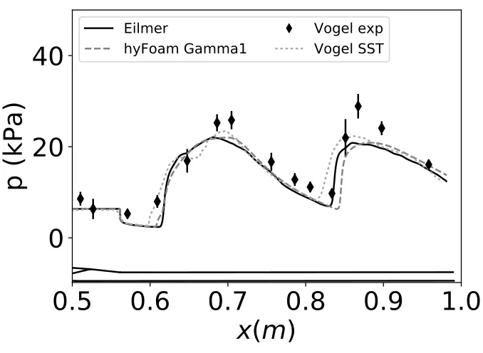
Figure 12: Complete geometry wall pressure comparison of CFD with experiment at injector side After the SWBLI, the wall pressure (Figure 13) profiles of Eilmer and hyFoam have a similar trend until the next reflection atx≈0.84m. At that position hyFoam predicts a reflection further downstream com-pared to Vogel SST and Eilmer. The latter solver agrees better with the experimental values. The gradient in pressure after the reflection is very similar in hyFoam and Eilmer. Consequently the shift in pressure profile originated in this reflected region persists until the end of the geometry. In comparison to Vogel SST both solvers underpredict the peak values. Moreover, between the first and second reflection the reference CFD seems to capture a local minimum which is not captured on the mesh used by the present authors. Following these wall pressure observation with Eilmer and hyFoam, the Wilcox k-ω model seems to be more appropriate than the Menter SST version.
0.5 0.6 0.7 0.8 0.9 1.0
x(m)
0
20
40
p (kPa)
Eilmer
[image:14.612.136.475.73.321.2]hyFoam Gamma1
Vogel exp
Vogel SST
Figure 13: Isolator wall pressure comparison of CFD with experiment at injector side
1
2
3
4
5
Mach
0.01
0.00
0.01
Eilmer
hyFoam Gamma1
Figure 14: Mach number profiles of Eilmer and hy-Foam at x=55 cm for the dual-mode scramjet test case.
400
600
800
T (K)
0.01
0.00
0.01
Eilmer
[image:14.612.74.297.374.527.2]hyFoam Gamma1
Figure 15: Temperature profiles of Eilmer and hy-Foam at x=55 cm for the dual-mode scramjet test case.
[image:14.612.323.536.377.528.2]on the final solution with only small differences observed between Eilmer and hyFoam. Consequently this study confirmed the capability of hyFoam in addressing steady state supersonic internal flows. Improvements could be obtained for the test cases considered in this work by implementing the Wilcox 2006 k-ωturbulence model. In terms of computational cost, hyFoam was observed to be less demanding than Eilmer. However, given the availability of Wilcox 2006 k-ωturbulence model, the previously validated combusting capability,29
and the developments on the way to improve the performance (unstructured and implicit) of the code for high speed internal and external flows, Eilmer will be selected by the authors for future studies.
IV.
Conclusion
Two open-source CFD codes Eilmer and hyFoam are considered to simulate the physics of supersonic flows for propulsion applications in a steady state. The assessment is performed with two scramjet type test cases on the same computational grids. Regarding the computational cost hyFoam did perform better than Eilmer which was expected given the fully explicit character of the latter code. In terms of accuracy both solvers have a similar prediction capability when no chemical reactions are considered. The spatial dis-cretization treatment resulted in only slight differences in inlet shock predictions. An important discrepancy is observed in the shock induced boundary layer separation bubble, typical of scramjet flows. The reason for this discrepancy is thought to be related the use of Wilcox 2006 (Eilmer) and Menter’s SST (hyFoam) k-ω
turbulence model. Observations on the impact of the separation region on the downstream shock train with experimental data suggest the use of the former turbulence model to be more adequate. It must be noted that this study needs to be pursued further to include also the effect of mesh resolution in order to eventually compare mesh independent results for both solvers. Nevertheless, both solvers demonstrate a capability to be used as design tools and in a next step the effect of combustion on the overall engine performance will be evaluated.
Acknowledgments
The authors would like to express their gratitude to Dr. Jack Edwards from North Carolina State Uni-versity for the dual-mode scramjet geometry details. A special thanks to Tom J. Scanlon from the UniUni-versity of Strathclyde and Peter Jacobs from the University of Queensland for their advice during the process of realizing this work. Results were obtained using the EPSRC funded ARCHIE-WeSt High Performance Com-puter (www.archie-west.ac.uk). EPSRC grant no. EP/K000586/1.
References
1Bruno, C. and Czysz, P. A.,Future spacecraft propulsion systems: enabling technologies for space exploration, Springer
Science & Business Media, 2009.
2Jazra, T. and Smart, M. K., “Design Methodology for the Airbreathing Second Stage of a Rocket-Scramjet-Rocket
Launch Vehicle,”17th AIAA International Space Planes and Hypersonic Systems and Technologies Conference, San Francisco,
California, 2011.
3Escher, W. and Flornes, B., “A Study of Composite Propulsion Systems for Advanced Launch Vehicle Applications,”
Tech. rep., Vol 7, The Marquardt Corporation, Van Nuysm CA, 1966.
4Mankins, J., “Highly reusable space transportation: Advanced concepts and the opening of the space frontier,”Acta
Astronautica, Vol. 51, No. 10, 2002, pp. 727–742.
5O’Byrne, S., Doolan, M., Olsen, S., and Houwing, A., “Measurement and imaging of supersonic combustion in a model
scramjet engine,”Shock Waves, Vol. 9, No. 4, 1999, pp. 221–226.
6Lorrain, P., Capra, B., Brieschecnk, S., and Boyce, R., “A Detailed Investigation of Nominally 2-D Radical Farming
Scramjet Combustion,”18th AIAA/3AF International Space Planes and Hypersonic Systems and Technologies Conference, 2012, p. 5812.
7Edwards, J. R., Boles, J. A., and Baurle, R. A., “Large-eddy/Reynolds-averaged Navier–Stokes simulation of a supersonic
reacting wall jet,”Combustion and Flame, Vol. 159, No. 3, 2012, pp. 1127–1138.
8Edwards, J. R. and Fulton, J. A., “Development of a RANS and LES/RANS Flow Solver for High-Speed Engine Flowpath
Simulations,”20th AIAA International Space Planes and Hypersonic Systems and Technologies Conference, 2015, p. 3570.
9Engblom, W., Frate, F., and C.C., N., “Progress in validation of WIND-US for ramjet/scramjet combustion,”43rd AIAA
Aerospace Sciences Meeting and Exhibit, Reno, Nevada, January 2005.
11Steelant, J., Mack, A., Hannemann, K., and Gardner, A., “Comparison of Supersonic Combustion Tests with Shock
Tunnels, FLight and CFD,”42nd AIAA/ASME/SAE/ASEE Joint Propulsion Conference and Exhibit, Sacramento, California, July 2006.
12Baurle, R. and Eklund, D., “Analysis of dual-mode hydrocarbon scramjet operation at Mach 4-6.5,”Journal of Propulsion
and Power, Vol. 18, No. 5, 2002, pp. 990–1002.
13Drummond, J. P., Danehy, P. M., Gaffney Jr, R. L., Tedder, S. A., Cutler, A. D., and Bivolaru, D., “Supersonic
combustion research at NASA,” 2007.
14Palacios, F., Colonno, M. R., Aranake, A. C., Campos, A., Copeland, S. R., Economon, T. D., Lonkar, A. K., Lukaczyk,
T. W., Taylor, T. W., and Alonso, J. J., “Stanford University Unstructured (SU2): An open-source integrated computational environment for multi-physics simulation and design,”AIAA Paper, Vol. 287, 2013, pp. 2013.
15Palacios, F., Economon, T. D., Aranake, A. C., Copeland, S. R., Lonkar, A. K., Lukaczyk, T. W., Manosalvas, D. E.,
Naik, K. R., Padr´on, A. S., Tracey, B., et al., “Stanford University Unstructured (SU2): Open-source analysis and design technology for turbulent flows,”AIAA paper, Vol. 243, 2014, pp. 13–17.
16Weller, H. G., Tabor, G., Jasak, H., and Fureby, C., “A tensorial approach to computational continuum mechanics using
object-oriented techniques,”Computers in physics, Vol. 12, No. 6, 1998, pp. 620–631.
17Chapuis, M., Fedina, E., Fureby, C., Hannemann, K., Karl, S., and Schramm, J. M., “A computational study of the
HyShot II combustor performance,”Proceedings of the Combustion Institute, Vol. 34, No. 2, 2013, pp. 2101–2109.
18Fureby, C., Nordin-Bates, K., Petterson, K., Bresson, A., and Sabelnikov, V., “A computational study of supersonic
combustion in strut injector and hypermixer flow fields,” Proceedings of the Combustion Institute, Vol. 35, No. 2, 2015, pp. 2127–2135.
19Droeske, N., Nizenkov, P., Vellaramkalayil, J. J., von Wolfersdorf, J., Makowka, K., and Sattelmayer, T., “Validation
of a Novel OpenFOAM Solver using a Supersonic, Non-reacting Channel Flow,”19th AIAA International Space Planes and
Hypersonic Systems and Technologies Conference, 2014, p. 3088.
20Makowka, K., Droeske, N., Vellaramkalayil, J. J., von Wolfersdorf, J., and Sattelmayer, T., “Unsteady RANS investigation
of a hydrogen-fueled staged supersonic combustor with lobed injectors,”19th AIAA International Space Planes and Hypersonic
Systems and Technologies Conference, 2014, p. 3215.
21Casseau, V., Palharini, R. C., Scanlon, T. J., and Brown, R. E., “A Two-Temperature Open-Source CFD Model for
Hypersonic Reacting Flows, Part One: Zero-Dimensional Analysis,”Aerospace, Vol. 3, No. 4, 2016, pp. 34.
22Casseau, V., Espinoza, D. E., Scanlon, T. J., and Brown, R. E., “A Two-Temperature Open-Source CFD Model for
Hypersonic Reacting Flows, Part Two: Multi-Dimensional Analysis,”Aerospace, Vol. 3, No. 4, 2016, pp. 45.
23Gollan, R. and Jacobs, P., “About the formulation, verification and validation of the hypersonic flow solver Eilmer,”
International Journal for Numerical Methods in Fluids, Vol. 73, No. 1, 2013, pp. 19–57.
24Chan, W., Jacobs, P., and Mee, D., “Suitability of the k–ωturbulence model for scramjet flowfield simulations,”
Inter-national Journal for Numerical Methods in Fluids, Vol. 70, No. 4, 2012, pp. 493–514.
25Sridhar, V., Gai, S., and Kleine, H., “A Numerical Investigation of Supersonic Cavity Flow At Mach 2,”18th Australasian
Fluid Mechanics Conference, Launceston, Australia, 2012.
26Sridhar, V., Gai, S., and Kleine, H., “Supersonic flow over a rectangular open cavity: effect of length-to-depth ratio,”
29th International Symposium on Shock Waves 1, Springer, 2015, pp. 429–434.
27Deepak, N., Gai, S., and Neely, A., “Aerothermodynamics of hypersonic shock wave boundary layer interactions,”Proc.
of 17th Australian Fluid Mechanics Conference, 2010.
28Chan, W. Y., Mee, D. J., Smart, M. K., and Turner, J. C., “Drag Reduction by Boundary-Layer Combustion: Effects of
Flow Disturbances from Rectangular-to-Elliptical-Shape-Transition Inlets,”Journal of Propulsion and Power, Vol. 31, No. 5, 2015, pp. 1256–1267.
29Kang, X., Gollan, R., Jacobs, P., and Veeraragavan, A., “Numerical Simulations of Premixed Combustion in Narrow
Channels,”19th Australasian Fluid Mechanics Conference, RMIT University, 2014.
30Baurle, R., “Modeling of high speed reacting flows: established practices and future challenges,”AIAA paper, Vol. 267,
2004, pp. 2004.
31Jacobs, P., Gollan, R., Denman, A., O’Flaherty, B., Potter, D., Petrie-Repar, P., and Johnston, I., “Eilmer’s theory book:
basic models for gas dynamics and thermochemistry,” Tech. rep., The University of Queensland, 2012.
32Gordon, S. and McBride, B. J., Computer program for calculation of complex chemical equilibrium compositions and
applications. I.Analysis, Citeseer, 1996.
33Alkandry, H., Boyd, I. D., and Martin, A., “Comparison of models for mixture transport properties for numerical
simulations of ablative heat-shields,”51st AIAA Aerospace Sciences Meeting including the New Horizons Forum and Aerospace
Exposition, number AIAA, Vol. 303, 2013.
34Wilcox, D. C., “Formulation of the k-ωturbulence model revisited,”AIAA journal, Vol. 46, No. 11, 2008, pp. 2823–2838. 35Menter, F. R., “Two-equation eddy-viscosity turbulence models for engineering applications,”AIAA journal, Vol. 32,
No. 8, 1994, pp. 1598–1605.
36Menter, F. and Esch, T., “Elements of industrial heat transfer predictions,” 16th Brazilian Congress of Mechanical
Engineering (COBEM), Vol. 109, 2001.
37Menter, F., Kuntz, M., and Langtry, R., “Ten years of industrial experience with the SST turbulence model,”Turbulence,
heat and mass transfer, Vol. 4, No. 1, 2003.
38Georgiadis, N. J., Yoder, D. A., Vyas, M. A., and Engblom, W. A., “Status of turbulence modeling for hypersonic
propulsion flowpaths,”Theoretical and Computational Fluid Dynamics, Vol. 28, No. 3, 2014, pp. 295–318.
39Macrossan, M., “The equilibrium flux method for the calculation of flows with non-equilibrium chemical reactions,”
Journal of Computational Physics, Vol. 80, No. 1, 1989, pp. 204–231.
40Wada, Y. and Liou, M., “A flux splitting scheme with high-resolution and robustness for discontinuities,”32nd Aerospace
41Liou, M., “Ten years in the making - AUSM-family.”AIAA Paper, 2001, pp. 2001–2521.
42Coratekin, T., Keuk, J. V., and Ballman, J., “Performance of upwind schemes and turbulence models in hypersonic
flows,”AIAA journal, Vol. 42, No. 5, 2004, pp. 945–957.
43Kurganov, A., Noelle, S., and Petrova, G., “Semidiscrete central-upwind schemes for hyperbolic conservation laws and
Hamilton–Jacobi equations,”SIAM Journal on Scientific Computing, Vol. 23, No. 3, 2001, pp. 707–740.
44Kurganov, A. and Tadmor, E., “New high-resolution central schemes for nonlinear conservation laws and convection–
diffusion equations,”Journal of Computational Physics, Vol. 160, No. 1, 2000, pp. 241–282.
45Greenshields, C. J., Weller, H. G., Gasparini, L., and Reese, J. M., “Implementation of semi-discrete, non-staggered
central schemes in a colocated, polyhedral, finite volume framework, for high-speed viscous flows,”International Journal for
Numerical Methods in Fluids, Vol. 63, No. 1, 2010, pp. 1–21.
46Jacobs, P. and Gollan, R., “Implementation of a compressible-flow simulation code in the D programming language,”
Applied Mechanics and Materials, Vol. 846, Trans Tech Publ, 2016, pp. 54–60.
47Smayda, M., Vogel, P., Schultz, I., Hanson, R., Foelsche, R., Tsai, C., Cresci, D., and Goyne, C., “Hypervelocity Testing of
a Dual-mode Scramjet,”50th AIAA Aerospace Sciences Meeting Including the New Horizons Forum and Aerospace Exposition, 2012, p. 481.
48Lorrain, P., Brieschenk, S., and Boyce, R., “Experimental investigation of inlet-injection radical-farming scramjet
com-bustion,”XXI International Symposium on Air Breathing Engines (ISABE 2013), Vol. 1, Curran Associates, 2013, pp. 1–9.
49Tirtey, S., Boyce, R., Brown, M., Capra, B., Creagh, M.and Dedman, A., Dimitrijevic, I., Pudsey, A., Sharp, B.,
Van Standen, P., et al., “SCRAMSPACE: Radical-Farming Scramjet for access to space,”STO-EN-AVT-234 Hypersonic Flight
Testing, 2014.
50Mogavero, A., Taylor, I., and Brown, R., “Hybrid Propulsion Parametric and Modular Model: a novel engine analysis
tool conceived for design optimization,” 19th AIAA International Space Planes and Hypersonic Systems and Technologies
Conference, Atlanta GA, 2014, pp. 16–20.
51Toro, E. F.,Riemann solvers and numerical methods for fluid dynamics: a practical introduction, Springer Science &
Business Media, 2013.
52Goldberg, U., Peroomian, O., Chakravarthy, S., and Sekar, B., “Validation of CFD++ code capability for supersonic
combustor flowfields,”AIAA paper, Vol. 3271, 1997.
53Lorrain, P., Flow structure/chemistry coupling in the ignition process in shock-induced-combustion scramjets, Ph.D.
thesis, University of Queensland, Australia, 2014.
54Jasak, H., Weller, H., and Gosman, A., “High resolution NVD differencing scheme for arbitrarily unstructured meshes,”
International journal for numerical methods in fluids, Vol. 31, No. 2, 1999, pp. 431–449.