Application of MPLS-TP for Transporting Power
System Protection Data
Steven M. Blair and Campbell D. Booth
University of StrathclydeGlasgow, UK [email protected]
Jurgen Michielsen
OTN Systems Antwerp, BelgiumNilesh Joshi
CommTel Network SolutionsMelbourne, Australia
Abstract—Power utilities are increasingly dependent on the use of communications networks. These networks are evolv-ing to be packet-based, rather than usevolv-ing conventional Time-Division Multiplexing (TDM) technologies. Transporting current differential protection traffic over a packet network is especially challenging, due to the safety-critical nature of protection, the strict requirements for low delay and low asymmetrical delay, and the extensive use of legacy TDM-based protocols.
This paper highlights the key technical characteristics of Multi-Protocol Label Switching-Transport Profile (MPLS-TP), and demonstrates its application for transporting current differ-ential protection traffic. A real-time hardware-in-the-loop testing approach has been used to thoroughly validate the technologies in various configurations. It is demonstrated that MPLS-TP technologies can meet the requirements of current differential protection and other, less critical applications. In particular, it is shown that delay and asymmetrical delay can be controlled through the inherent use of bi-directional paths—even when “hitless” link redundancy is configured. The importance of ap-propriate traffic engineering, clocking schemes, circuit emulation methods is also demonstrated.
Index Terms—MPLS-TP, power system protection, time syn-chronization, wide-area communications.
I. INTRODUCTION
Power utilities rely on communications networks for many operational activities [1], [2]. Applications such as teleprotec-tion and supervisory control and data acquisiteleprotec-tion (SCADA) cannot operate without an appropriate and reliable telecommu-nications infrastructure. New applications, such as IEC 61850-based protection schemes and Synchrophasors, are packet-based. Therefore, to transport these applications efficiently, many electrical utilities have migrated to, or are evolving towards, packet-based networking infrastructure.
There are challenges in adopting packet-based networking for typical utility applications—particularly for power sys-tem protection which commonly relies upon Time-Division Multiplexing (TDM) technologies. The knowledge of legacy telecoms technologies is declining; new telecoms engineers are skilled in Ethernet and IP technology but not in conventional TDM technologies. Similarly, vendors providing telecoms products are advancing packet-based networking technologies, rather than the further development of TDM equipment. Exist-ing TDM equipment—that is not yet obsolete—will become obsolete in the near future and will become increasingly costly to maintain.
Internet Protocol/Multi-Protocol Label Switching (IP/M-PLS) has become the de-facto standard for telecoms operator infrastructure in the core of the network, and utilities are adopting it for their next generation networks. The capa-bilities of IP/MPLS with utility-specific applications such as teleprotection have been demonstrated [3]–[5]. However, IP/MPLS was not designed with the inherent capability to transport power utility data. A Transport Profile within MPLS, known as MPLS-TP, has the potential to directly address the requirements and technical challenges of utility applications. MPLS-TP provides the ability to guarantee performance for legacy circuit-based applications, because paths are always bidirectional (in IP/MPLS paths are unidirectional by nature). The complex set of protocols to organise the network (the so called “control plane”) is replaced by a management platform to create real end-to-end service provisioning, which makes it simpler to provision and maintain the network. Failover switching mechanisms can ensure reliable and deterministic services on the network, even following failures.
This paper demonstrates the application of MPLS-TP for transporting current differential protection data. This is the most critical and demanding application of communications within power utility operations, and therefore proves that the technology is suitable for many other utility applications. The paper also highlights the key technologies involved, demon-strates a comprehensive validation of the application of MPLS-TP in multiple scenarios, and provides critical observations of the trade-offs in configuring an MPLS-TP network.
II. CHALLENGESTRANSPORTINGCURRENT DIFFERENTIALPROTECTIONTRAFFIC
issue a trip signal to circuit breakers to isolate the faulted line from the rest of the system.
Timing is critical in protection applications. The messages between protection relays must be transported as fast as possible to ensure that there are no undue delays involved in isolating power system faults. Therefore, the propagation delay must be kept within a few milliseconds, depending on the application and the utility’s protection policy. Furthermore, some implementations are sensitive to asymmetrical delay (or differential delay) [5], [6], where the delays in the “forward” and “reverse” directions are not equal.
There are several proprietary (i.e., vendor-specific) and standardised protocols for transporting teleprotection traffic. Two protocols—one TDM-based, and one packet-based—are analysed in this paper:
1) IEEE C37.94 [7] is a TDM-based protocol which pro-vides 64 kbps TDM timeslots over an optical physical layer. The number of timeslots can be selected: the use of more slots reduces the propagation delay, at the expense of greater bandwidth use. Relays use the protocol to transmit current phasor data and timing information.
2) IEC 61850-9-2 Sampled Values [8], using the so-called “LE” guideline format [9], maps raw voltage and current sensor values into multicast Ethernet frames. This re-quires relatively high bandwidth: approximately 5 Mbps per data stream. Sampled Values is typically comple-mented by GOOSE messaging for trip messages from the protection relays to circuit breakers.
III. MPLS-TP: KEYTECHNOLOGIES
A. Overview
MPLS is a feature-rich protocol suite standardized by the Internet Engineering Task Force (IETF) over the last 15 years. The basis of MPLS is IP technology and is therefore often called IP/MPLS. Over the years, IP/MPLS has become a large toolbox to solve many challenges in networking environments. Some vendors have extended the use of IP/MPLS from IT-oriented applications to critical utility applications such as power system protection. However, the technologies were not originally designed to transport such time-critical applications, and there is complexity associated with configuring an IP/M-PLS network to guarantee performance under all conditions. As the number of devices connected at the “edge” of the network increases (i.e. where, for a power a utility, devices such as protection IEDs connect), the complexity of the IP/M-PLS control plane can become unmanageable. In addition, at the edge of the network, full “meshing” is often not possible which limits the options for an efficient defence of the network against link or node failures with IP/MPLS. This is why the telecoms industry, together with the main standardisation bodies of the telecoms industry (the IETF and International Telecommunication Union), have standardised MPLS-TP. The key features of MPLS-TP include the following:
[image:2.612.337.540.48.252.2]• Network failover and activation of backup scenarios, which do not depend on dynamic protocols that control
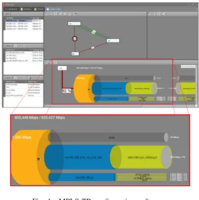
Fig. 1. MPLS-TP configuration software
the network. This makes the network predictable and dependable.
• Bidirectional paths and bidirectional failover switching, which guarantees symmetrical connections with very low asymmetrical delay under all circumstances.
• “In-band” Operations, Administration, and Management (OAM)—i.e. the OAM packets follow the same path as the user data—allows verification of the performance of services during operation.
• Static provisioning through a network management sys-tem including traffic engineering to create paths based on service requirements and not based on network internals, so that the operator has full control over the paths.
• Isolation of service data and control plane packets. The following sub-sections describe the key technologies in detail.
B. Traffic Engineering
To be able to build a network that is capable of transporting critical and non-critical traffic, the network has to be “traffic engineered”. This means that traffic flows have to be identified on the network and treated according their service level agree-ments. The main tools are admission control, policing, and shaping. These ensure that a network has suitable resources to transport a service, and can measure the traffic and remove any excess traffic when needed.
Another tool that a packet network can offer is prioriti-sation of traffic. This means that traffic is identified to be critical (high priority) or non-critical (low priority). In a well-engineered network, critical traffic flows through the network as if there was no other traffic on the network, and therefore experiences minimal delays and jitter.
service is created on the network by the management system. The management system then uses these parameters to define the “shapers” and “policers” of the service at a network-wide level. Fig. 1 illustrates the use of an MPLS-TP management system to define and visualize configuration parameters such as bandwidth and the links that are used for the service under test.
C. Clocking Types
Differential protection relays typically require some form of time synchronization, often over long distances. As per the IEEE C37.94 specification, protection relays should be configured to “slave” their clocking from the communications network (i.e. extract the clock from the local MPLS-TP router). To achieve synchronization between the two (or more) IEEE C37.94 interface ports across an MPLS-TP network, different options are possible:
1) Synchronize the network via Synchronous Ethernet and use a so-called “internal clocking” scheme. Synchronous Ethernet (SyncE) allows the distribution of a common frequency via the physical link between the nodes. As a result, all synchronized nodes have the same frequency. This frequency can then be used to directly synchronize the C37.94 interface ports across multiple distributed relays. This scenario is useful if a single clocking domain for all protection relays is the goal, and if there is physical-layer support for SyncE.
2) “Differential clocking” is similar to internal clocking, but it allows a different clocking domain per service (e.g. per pair of protection relays) which gives the advantage that different TDM oriented data (e.g. voice and telepro-tection) do not have to be in the same clocking domain. This offers greater flexibility when implementing differ-ent types of services over the network. This technology also requires that the network is synchronized via SyncE because it requires to have the same reference frequency. 3) When no synchronization is possible between the two nodes, a third option, called “adaptive clocking”, can be used. With adaptive clocking, the reconstruction of the clock on the specific service is based on the average arrival time of packets. This has the advantage that no direct synchronization, such as SyncE, is required, but very strict traffic engineering of the network is essential to avoid large packet delay variation which would influence the relative accuracy of the relay clocks.
D. Service Types
The IEEE C37.94 standard expects a circuit-based commu-nications link between relays, and there is a choice of ap-proaches for emulating this over a packet network. Structure-Agnostic Time Division Multiplexing over Packet (SAToP) is a technology where the entire C37.94 frame is packetized and transported over the network (where the C37.94 frame is a 2 Mbps signal). This technology is fast but requires more band-width than CESoPSN (see below). Bandband-width requirements can vary between 3.6 Mbps for a packetization of four C37.94
frames per Ethernet packet and 8.2 Mbps for a packetization of one C37.94 frame per Ethernet packet.
Circuit Emulation Service over Packet Switched Network (CESoPSN) transmits only a subset of the C37.94 frame. As per the standard, the useful data of a C37.94 frame is between 1 and 12 timeslots (this is the so-called N value). A single timeslot is 64 kbps. With CESoPSN, the “useful” timeslots are extracted and only this data is transported over the service. As a result, bandwidth can be saved. Bandwidth can be as low as 2.3 Mbps for N=12 (i.e. 12 timeslots) and a packetization of four C37.94 frames per Ethernet packet. When the same useful data is transported but only one C37.94 frame is transported, the bandwidth requirement is 7 Mbps. The drawback of this technology is the fact that the C37.94 frames have to be interpreted which can cause an additional delay of 700 µs within the end-to-end delay.
For transporting Ethernet-based services over a wide area network, E-Line can be used to connect two end-points. This means that only the two points that are configured in this service can communicate as if they would have their own private Ethernet connection. Alternatively, E-LAN can be used for multipoint connections; in a multipoint service, more than two ports can be added and these ports can communicate with each other as if they reside on a private LAN. Other ports on the network have no access to the service.
IV. VALIDATION OFMPLS-TPFORCURRENT DIFFERENTIALPROTECTION
A. Overview
It is important to systematically validate the MPLS-TP technologies to ensure that they are suitable for the demands of power system protection applications. Network performance, including delay and asymmetrical delay, has been tested with legacy teleprotection under different kinds of circuit emulation methods, background traffic, network failover (the use of alternate communications paths following link or node failure), migration scenarios, and communications fault scenarios. The performance of the network with IEC 61850 traffic (Sampled Values and GOOSE) traffic has also been tested.
An MPLS-TP network has been implemented using commercially-available off-the-shelf equipment (based on the XTran platform), as illustrated in Fig. IV. In order to im-plement various network migration scenarios, a link between two MPLS-TP nodes has been established via an SDH net-work; thus, Ethernet over SDH/SONET has been implemented. Protection equipment has been connected via IEEE C37.94 (legacy teleprotection) and Ethernet (IEC 61850) interfaces.
B. Legacy Protection Validation
Fig. 2. Validation overview
(a) Real-time simulation laboratory
(b) MPLS-TP equipment
Fig. 3. Hardware-in-the-loop testing environment
represent a real power system—are supplied to the relays. With the RTDS monitoring software, it is also possible to precisely measure trip performance and the presence of potential false trips caused by misconfiguration of the communications net-work.
The protection relays have been configured to measure the end-to-end propagation delay from the relay’s perspective. To provide a more detailed measurement of the network perfor-mance between the two end-points of the IEEE C37.94 service, a custom measurement card has been used. This measurement card, installed in one of the MPLS-TP nodes, temporarily replaces the protection relays. It is able to measure the delay in both directions and calculate the actual asymmetrical delay between two devices by introducing a recognizable pattern in the IEEE C37.94 data. The card then displays the delay and asymmetrical delay over time in a user-friendly way (Fig. 4).
[image:4.612.350.527.50.169.2]To verify protection performance under various adverse load scenarios, the network has been loaded with parallel excessive
Fig. 4. Asymmetrical (or differential) delay monitoring
Fig. 5. Ethernet load injection
Ethernet traffic, with various the packet sizes, including the use of jumbo frames. An external, off-the-shelve Ethernet tester has been used, as illustrated in Fig. 5, to introduce extra traffic on the network. The tester created data flows with a fixed or random packet size with a configurable network load.
1) Delay and asymmetrical delay results: With legacy protection, the network delay varies based on the configuration of the circuit emulation stream (which is a trade-off between bandwidth and delay). The end-to-end delay of the service is driven by the packetization delay and by the size of the jitter buffer used on the service. This jitter buffer is located at the egress router of the service where the TDM data is restored (i.e. played-back to the receiving relay) and where continuous playout of data must be guaranteed. Buffer sizes of 3-6 ms have been tested for different configurations and the performance has been verified.
[image:4.612.73.275.177.483.2] [image:4.612.337.538.206.341.2]Fig. 6. Reproducible fiber cut hardware
bandwidth). Asymmetrical delay was always less than 500 µs with CESoPSN and less than 180 µs with SAToP. Note that network delay and asymmetrical delay are stable (and within the expected ranges) under all tested configurations.
A unique feature of the MPLS-TP provisioning tools, which are used to configure the communications network, is the ability to predict the delay when provisioning services. As shown in Table I, this prediction was in line with the measured values of the actual services. The additional background traffic had no measurable influence on the stability of the circuit emulation services.
To verify the actual trip times on the protection relays, electrical faults have been simulated within the RTDS, with the corresponding measurements being supplied to the relays, with the direct trip and inter-trip delays being recorded. Trip times can be as fast as 24.9 ms with a corresponding backup inter-trip time of 39.2 ms. The influence of the network was minimal compared to the back-to-back configuration (i.e. with the relays directly connected). There was no significant dif-ference between the trip performance of the different clocking schemes.
2) Network failover switching results: One of the chal-lenges in a packet-based network is to maintain symmetrical delay when the network has to reconfigure in a link failure situation. In MPLS-TP, this issue is managed by a standardized bidirectional failover switching feature.
An optical-to-electronic conversion board has been used to electronically create a convenient and repeatable “cut” in a single optical fiber, to facilitate the testing of link failures, as illustrated in Fig. 6. This provides a reproducible link failure, compared with manually disconnecting the fiber. After each link failure scenario, it was confirmed that asymmetrical delay remained constant following the failover switching.
The benchmark in telecoms networks is to provide backup activation after a failure in the network within 50 ms, similar to SDH/SONET technology. MPLS-TP can guarantee this protection switching via the standardised automatic protection switching. However, the tested MPLS-TP equipment can also protect services in a “hitless” manner. This allows 100% path protection (sometimes described as “1+1”) for all circuit emulation services, including IEEE C37.94. Hitless switching results in a small additional delay associated with the combi-nation of the latency of the delay difference between the two paths and additional buffering. I.e. to eliminate the impact of
the switch-over, the longest delay from the two paths must be used—regardless of the “active” path delay.
All features and functions described above have been fully tested. Based on the gathered test results it can be concluded that, before and after the switch-over, the delay and asymmet-rical delay remain within expected values. A small change in asymmetrical delay can occur because the data stream into the jitter buffer is interrupted at failover and can cause a lock on a slightly higher or lower level (i.e. the jitter buffer is reset, and may restart playing-out with a slightly different average delay). However, all test results showed the expected values and are in range with the industry norms for protection functionality.
C. IEC 61850-Based Protection Validation
Although protection implemented via IEEE C37.94 inter-faces remains very common, vendors of protection relays are providing next-generation protection applications using IEC 61850 messaging (using the Sampled Values and GOOSE protocols). To verify the capabilities of MPLS-TP with IEC 61850 traffic, a configuration implementing streams of Sam-pled Values and GOOSE messaging has been validated. Using the RTDS simulation model, Samples Value data streams, generated from an emulated Merging Unit, have been sent to protection relays at both ends of the transmission line. The remote messages were then compared with the local Sampled Values data stream to perform differential protection. In the case of fault detection, the protection relay transmitted a GOOSE message to activate a local and a remote circuit breaker. The protection functionality was implemented via an external IEC 61850-enabled microcontroller as described in [2].
1) GOOSE traffic: MPLS-TP routers are capable of trans-porting GOOSE traffic in a point-to-point or multipoint ser-vice (i.e. an E-Line or E-LAN). GOOSE transport has been tested with a service providing bandwidth of 500 kbps. The additional delay due to the network was approximately 20-40 µs (with a measurement resolution of 20 µs). When the network is loaded with parallel traffic, there was no noticeable influence when GOOSE traffic was configured as high priority. In addition, if GOOSE traffic gets competition from other traffic in the same class of service, the GOOSE traffic was still effectively transported due to the strict admission control and traffic engineering of the MPLS-TP platform.
The Ethernet services can be protected via MPLS-TP in a sub-50 ms failover scheme. Due to specific nature of GOOSE traffic (i.e. its periodic retransmission requirement), the impact of the failover switching varies between no impact (when the network convergence happens in between two GOOSE transmissions) and approximately 64 ms (when the network convergences cause a missing GOOSE message and the IED has to wait for the next GOOSE retransmission). Of course, this behaviour may not be suitable for GOOSE trip messages which are event-driven, and therefore hitless backup paths should be provisioned.
TABLE I
SUMMARY OF TYPICAL RESULTS
Test Service type
Clocking scheme
Time slots (1-12)
TDM frames per packet
Jitter buffer size (ms)
Calculated bandwidth (Mbps)
Calculated Delay (ms)
Measured Delay (ms)
Measured Asymmetrical
Delay (ms)
1 CESoPSN Internal 12 1 3 6.98 3.78 3.68 0.38
2 CESoPSN Differential 12 1 3 7.74 3.79 3.63 0.30
3 CESoPSN Adaptive 12 1 3 6.98 3.78 3.57 0.48
4 CESoPSN Internal 12 4 3 2.32 4.67 4.11 0.06
5 CESoPSN Internal 12 1 6 6.98 5.28 5.38 0.18
6 SAToP Internal 12 1 3 8.26 3.00 2.79 0.03
major differences between a packet-based network and a TDM network. In a packet network, speed is based on the QoS configuration, whereas in TDM networks speed is increased by increasing the bandwidth.
2) Sampled Values: Sampled Values has been tested with different VLAN configurations and service schemes, with a provisioned service bandwidth of 6 Mbps. An MPLS-TP net-work delay of <20 µs has been measured. When the netnet-work is loaded with additional traffic, there is no noticeable influence when traffic engineering is correctly configured and Sampled Values traffic is configured as high priority. Note that it is also possible to transport Sampled Values traffic in a logical ring. This is effectively a multipoint service but with a much higher efficiency then a standard multipoint service using MPLS.
Failover switching on the service after a network failure transporting the Sampled Values, caused an interruption of the data with the duration of the reconfiguration (26-40 ms). This is due to the nature of the Sampled Values protocol, which is a continuous data stream. Therefore, as for GOOSE trip messages, hitless backup paths should be provisioned for critical protection traffic.
V. CONCLUSIONS
Due to the rich transport capabilities of MPLS-TP, this sub-set of the MPLS standard is well-suited for replacing the aging SDH/SONET infrastructure presently used by many power utilities. MPLS-TP combines the efficiency of packet-based networks with the ease-of-use and deterministic behaviour of a conventional transport network.
MPLS-TP networks can be implemented with reliable pro-tection schemes such as hitless switching. Such a network al-lows the successful transport of legacy and IEC 61850 schemes under numerous configurations. When transporting legacy protection, it is important to implement traffic engineering correctly. Therefore, a user-friendly configuration and man-agement platform—to allow utilities to configure the system correctly, with minimal training requirements—is very impor-tant. Predictive performance of the system, such as estimated delay values, adds further convenience for users. Furthermore, for the transport of IEEE C37.94-based protection services, network designers have to pay special attention to implement an appropriate clocking scheme. The highest level of reliability
can be realised with differential clocking in combination with hitless switching. When a reliable and redundant clocking scheme is not possible, an adaptive clocking scheme is a useful alternative when combined with strict admission control and traffic engineering to minimise asymmetrical delay.
This validation work described in this paper shows that the traffic engineering capabilities and strict guidance of the management platform, can provide a multiservice backbone for present and future critical protection applications.
REFERENCES
[1] W. Luan, D. Sharp, and S. Lancashire, “Smart grid communication network capacity planning for power utilities,” inIEEE PES T&D 2010. IEEE, 2010, pp. 1–4.
[2] S. M. Blair, F. Coffele, C. D. Booth, and G. M. Burt, “An Open Platform for Rapid-Prototyping Protection and Control Schemes with IEC 61850,” IEEE Trans. Power Deliv., vol. 28, no. 2, pp. 1103–1110, 2013. [3] P. Beaumont, F. Kawano, A. Kawarada, T. Kase, H. Sugiura, F. Lam,
J. Hurd, P. Worthington, D. Richards, and P. Merriman, “Performance evaluation of current differential relays over a wide area network,” in 11th IET Int. Conf. Dev. Power Syst. Prot. (DPSP 2012). IET, 2012, pp. 152–152.
[4] S. M. Blair, F. Coffele, C. Booth, B. De Valck, and D. Verhulst, “Demonstration and analysis of IP/MPLS communications for delivering power system protection solutions using IEEE C37.94, IEC 61850 Sampled Values, and IEC 61850 GOOSE protocols,” inCIGRE Paris Sess. B5, aug 2014.
[5] S. M. Blair, C. D. Booth, B. D. Valck, D. Verhulst, C. Kirasack, K. Y. Wong, and S. Lakshminarayanan, “Validating Secure and Reliable IP/MPLS Communications for Current Differential Protection,” inDev. Power Syst. Prot., 2016.
[6] J. Jesus, C. Diago, R. Lobo, S. M. Blair, and B. D. Valck, “MPLS networks for inter substation communication for current differential protection applications in digital substations,” in PAC World Conf., Zagreb, 2014. [Online]. Available: http://strathprints.strath.ac.uk/48807/ 1/PP021.pdf
[7] IEEE, “C37.94-2002 - IEEE Standard for N Times 64 Kilobit Per Second Optical Fiber Interfaces Between Teleprotection and Multiplexer Equipment,” 2003.
[8] IEC TC 57, “Communication networks and systems in substations Part 9-2: Specific Communication Service Mapping (SCSM) - Sampled values over ISO/IEC 8802-3 (IEC 61850-9-2:2011),” 2011.
[9] UCA International Users Group, “Implementation Guide-line for Digital Interface to Instrument Transform-ers Using IEC 61850-9-2,” Tech. Rep., 2004. [On-line]. Available: http://iec61850.ucaiug.org/ImplementationGuidelines/ DigIF{_}spec{_}9-2LE{_}R2-1{_}040707-CB.pdf