UNIVERSITI TEKNIKAL MALAYSIA MELAKA FAKULTI KEJURUTERAAN ELEKTRIK
FINAL YEAR PROJECT REPORT
PSO-TUNED PID CONTROLLER FOR COUPLED-TANK SYSTEM (CTS)
VIA PRIORITY-BASED FITNESS SCHEME
SHARIFAH YUSLINDA BINTI SYED HUSSIEN B011110227
i
“I hereby declare that I have read through this report entitle “PSO-Tuned PID Controller for Coupled-Tank System (CTS) via Priority-based Fitness Scheme” and found out that it has comply the partial fulfillment for awarding the degree of Bachelor of Electrical Engineering (Control, Instrumentation and Automation)”
Signature :………
Supervisor’s Name :………
ii
PSO-TUNED PID CONTROLLER FOR COUPLED-TANK SYSTEM (CTS) VIA PRIORITY-BASED FITNESS SCHEME
SHARIFAH YUSLINDA BINTI SYED HUSSIEN
A report submitted in partial fulfillment of the requirements for the degree of Bachelor of Electrical Engineering (Control, Instrumentation and Automation)
Faculty of Electrical Engineering
UNIVERSITI TEKNIKAL MALAYSIA MELAKA
iii
I declare that this report entitle “PSO-Tuned PID Controller for Coupled-Tank System(CTS) via Priority-based Fitness Scheme” is the result of my own research except as cited in the
references. The report has not been accepted for any degree and is not concurrently submitted in candidature of any other degree.
Signature :………
Name :………
iv
v
ACKNOWLEDGEMENT
A major research project like this is never the work of anyone alone. The contributions of many different people, in their different ways, have made this possible. I would like to extend my appreciation especially to the following.
I would like to express my sincere gratitude to my supervisor, Mr. Hazriq Izzuan Jaafar for the continuous support on my final year project research, for his patience, motivation, enthusiasm, and immense knowledge. His guidance helped me in all the time of research and completing this project. I could not have imagined having a better supervisor, mentor and guidance in completion of my final year project in Universiti Teknikal Malaysia Melaka.
Besides my supervisor, I would like to thank to all the lecturers that helped me throughout the completion of the project and always willing to help and gives their best suggestions. Without their support and guidance, this project will not complete as what I wanted.
Moreover, I would like to express my gratitude to all my fellow friends who always there cheering me up and stood by me through the good and bad times. Completing this project would not have been possible without their helps and support.
vi
ABSTRACT
vii
ABSTRAK
viii
TABLE OF CONTENT
CHAPTER TITLE PAGE
ACKNOWLEDGEMENT ABSTRACT
v vi
TABLE OF CONTENT viii
LIST OF TABLES xi
LIST OF FIGURES xiii
LIST OF APPENDICES xvi
1 INTRODUCTION 1
1.1 Coupled-Tank System (CTS) 1
1.2 Problem Statement 2
1.3 Objectives 3
1.4 Scopes 3
2 LITERATUE REVIEW 4
2.1 Theory And Bacic Principle 4
2.1.1 PID Controller 4
2.1.2 Conventional Tuning Method Of Pid Controller 6
2.1.2.1 Manual Tuning 6
2.1.2.2 Ziegler-Nichols (Z-N) 6
2.1.2.3 Cohen-Coon (C-C)
2.1.2.4 Particle Swarm Optimization (PSO)
8 9
ix
2.3 Summary Of Review 13
3 METHODOLOGY 17
3.1 Overview 17
3.2 Project Flowchart 18
3.3 Mathematical Modeling 20
3.3.1 A Simple Nonlinear Model 20
3.3.2 A Linerised Perturbation Model 22
3.3.3 First-Order Single-Input Single- Output Plant 24 3.3.4 A Second-Order Single Input
Single-Output Plant
25
3.4 Matlab Simulink 27
3.5 Conventional Tuning Method 28
3.5.1 Sshaped Response Curve 28
3.5.2 Zigler-Nichols (Z-N) Method 30
3.5.3 Cohen-Coon (C-C) Method 30
3.6 Cupled-Tank System (CTS) 31
3.7 DAQ Card
3.8 System Identification
3.9 Particle Swarm Optimization (PSO) 3.10 Priority Fitness based on PSO (PFPSO)
34 35 40 41
4 RESULT AND DISCUSSION 44
4.1 Coupled-Tank System (CTS) based on CTS Manual 4.1.1 Open-Loop System (Without Controller)
4.1.2 Stability of Open-Loop System
44 44 44
4.1.3 Manual Tuning (Trial And Error) 47
4.1.4 Auto-tuning Method 49
4.1.5 Ziegler-Nichols (Z-N) Method 50
4.1.6 Cohen-Coon (C-C) Method
4.1.7 Particle Swarm Optimization (PSO) Method
x
4.1.8 Priority Fitness based on PSO (PFPSO) Method 55 4.1.9 Summary Graphs
4.2 Coupled-Tank System based on Experimental 4.2.1 Open-Loop System (Without Controller) 4.2.2 Stability of Open-Loop System
4.2.3 Closed-Loop System (Without Controller) 4.2.4 Particle Swarm Optimization (PSO) Method 4.2.5 Priority Fitness based on PSO (PFPSO) Method 4.2.6 Summary Graphs
57 60 60 61 63 64 66 68
5 CONCLUSION AND RECOMMENDATION 70
5.1 Conclusion 70
5.2 Recommendation/Future Work 70
REFERENCES 71
xi
LIST OF TABLES
TABLE TITLE PAGE
2.1 PID controller properties 5
2.2 Closed-loop Ziegler-Nichols method in PID Controller 7
2.3 Open-loop Ziegler-Nichols method in PID Controller 7
2.4 Cohen-Coon method in PID Controller 8
2.5 Summary of Review 13
3.1 3.2 3.3 3.4
Parameter of CTS referred from manual CTS-001
Calibration readings for tank 1 level sensor with pump voltage of 1.6V Calibration readings for tank 2 level sensor with pump voltage of 1.8V Calibration of the controlled inflow (pump)
27 31 32 32 4.1 4.2 4.3 4.4 4.5 4.6 4.7 4.8 4.9
Performance of open-loop system without controller based on CTS manual [1]
Routh-Hurwitz table
Routh-Hurwitz table for CTS based on CTS manual [1] Stability of the CTS based on CTS manual [1]
Performance of closed-loop system with PID controller by using tuning method of trial and error method based on CTS manual [1]
Performance of closed-loop system with PID controller by using tuning method of auto-tuning method based on CTS manual [1]
Performance of closed-loop system with PID controller by using tuning method of Z-N method based on CTS manual [1]
Performance of closed-loop system with PID controller by using tuning method of C-C method based on CTS manual [1]
The characteristics of PSO based on CTS manual [1]
xii 4.10 4.11 4.12 4.13 4.14 4.15 4.16 4.17 4.18 4.19 4.20 4.21 4.22 4.23 4.24 4.25 4.26
The parameters of PID controller by PSO-tuned based on CTS manual [1]
Performance of CTS by using method of PSO based on CTS manual [1] The parameters of PID controller by PFPSO-tuned based on CTS manual [1]
Performance of CTS by using method of PFPSO based on CTS manual [1]
Summary of the parameters of PID controller by using classical and optimizations tuning method based on CTS manual [1]
Summary of transient response specification of PID controller by using classical and optimizations tuning method based on CTS manual [1] Performance of open-loop system without controller based on experimental
Routh-Hurwitz table for CTS based on experimental Stability of the CTS based on experimental
Performance of closed-loop system based on experimental
The parameters of PID controller by PSO-tuned based on experimental Performance of CTS by using method of PSO based on experimental The parameters of PID controller by PFPSO-tuned based on experimental Performance of CTS by using method of PFPSO based on experimental Summary of the parameters of PID controller by using optimizations tuning based on experimental
Summary of transient response specification of PID controller by using optimizations tuning method
Comparison between PSO and PFPSO
xiii
LIST OF FIGURES
FIGURE TITLE PAGE
1.1 3.1 3.2
Coupled-tank apparatus CTS-001 Flowchart of project phase 1 Flowchart of project phase 2
1 18 19
3.3 Schematic diagram of CTS 20
3.4 Block diagram of second-order system 26
3.5 Block diagram of the open loop of CTS using simulink 28 3.6 3.7 3.8 3.9 3.10 3.11 3.12 3.13 3.14 3.15 3.16 3.17 3.18 3.19
S-shaped response curve
Step response of open-loop for CTS
Coupled-tank control apparatus model CT-100
Communication path between computer and coupled-tank System identification tool
Data of model in system identification
Data selection in working data and validation data in system identification
Model selection in the system identification
Characteristics selection in the system identification Model output of CTS in the system identification Model information in the system identification General process of PSO
General process of PFPSO
Process of PFPSO according to the priority
29 29 31 35 36 36 37 37 38 39 39 40 42 43 4.1 Block diagram of open-loop system without controller based on
CTS manual [1]
xiv
4.2 Response of open-loop system without controller based on CTS manual [1]
45
4.3 Block diagram of CTS with PID controller by using tuning method of trial and error method based on CTS manual [1]
47
4.4
4.5
Response of closed-loop system with PID controller by using tuning method of trial and error method based on CTS manual [1] Block diagram of CTS with PID controller by using tuning method of auto-tuning method based on CTS manual [1]
48
49
4.6 Setting of PID parameter by using auto-tuning method based on CTS manual [1]
49
4.7 Response of closed-loop system with PID controller by using tuning method of auto-tuning method based on CTS manual [1]
50
4.8 Response of closed-loop system with PID controller by using tuning method of Z-N method based on CTS manual [1]
51
4.9 Response of closed-loop system with PID controller by using tuning method of C-C method based on CTS manual [1]
52
4.10 Block diagram of CTS with PID controller by using tuning method of PSO based on CTS manual [1]
53 4.11 4.12 4.13 4.14 4.15 4.16
Sum Squared Error (SSE) vs iteration of PSO based on CTS manual [1]
Response of CTS by using tuning method of PSO based on CTS manual [1]
Response of CTS by using tuning method of PFPSO based on CTS manual [1]
Response of closed –loop system with PID controller by using conventional tuning methods based on CTS manual [1]
Response of closed–loop system with PID controller by using conventional and optimizations tuning methods based on CTS manual [1]
xv
4.17
4.18
4.19
4.20
4.21
4.22
4.23
Response of open-loop system without controller based on experimental
Response of closed-loop system without controller based on experimental
Block diagram of CTS with PID controller by using tuning method of PSO based on experimental
Sum Squared Error (SSE) vs iteration of PSO based on CTS experimental
Response of CTS by using tuning method of PSO based on experimental
Response of CTS by using tuning method of PFPSO based on experimental
Response of CTS with PID controller by using optimization tuning methods based on experimental
61
63
64
65
66
67
xvi
LIST OF APPENDICES
APPENDIX TITLE PAGE
A B C D E
Gannt Chart Data Collection
Data of Sum Squared Error (SSE) in CTS Publications
Turnitin Report
1
CHAPTER 1
INTRODUCTION
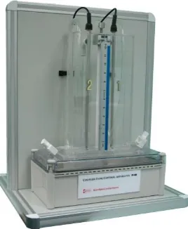
[image:18.612.248.382.382.545.2]1.1 Coupled-Tank System (CTS)
Figure 1.1: Coupled-tank apparatus CTS-001
2
as the tool of communications between the hardware and software. Through the software analysis, it enables to carry out the function of oscillation and display the input and output response. From the system, it also can verify the parameter of the model which can be derived from the mathematical modeling. This output response from the modeling function can be taken as the bench mark to achieve good response after implemented it in the CTS. The performance can easily be monitored in MATLAB simulation.
1.2 Problem Statement
3
1.3 Objectives
The objectives of this project are:
i. To model and simulate PID controller tuned by conventional method which are trial and error, auto-tuning, Ziegler-Nichols (Z-N) and Cohen-Coon (C-C) for CTS.
ii. To obtain optimal parameters of the PID controller for CTS using Priority-Fitness based Particle Swarm Optimization (PFPSO) as the tuning method.
iii. To compare the performance of CTS in terms of transient response specifications (settling time, overshoot, rise time and steady-state error) and validate it with PSO.
1.4 Scopes
The scopes of this project are:
i. Implemented PID controller in order to control the performance in terms of settling time of CTS.
ii. Apply PFPSO as the tuning method in finding the optimal parameters of PID controller of CTS.
4
CHAPTER 2
LITERATURE REVIEW
2.1 Theory and Basic Principle
The industrial CTS are widely used in consumer liquid proceeding and chemical processing industry. In order to control the level of the liquid, a conventional PID controller had been implemented. There are several methods to find the parameters for PID controllers such as trial and error method, Z-N method and C-C method.
2.1.1 PID Controller
5
) ( ) ( 1 ) ( ) ( ) ( ) ( ) ( ) ( t dt de T dt t e T t e K t u t dt de K dt t e K t e K t u d i p d i p (2.1) Where i p i T KK ; Kd KpTd
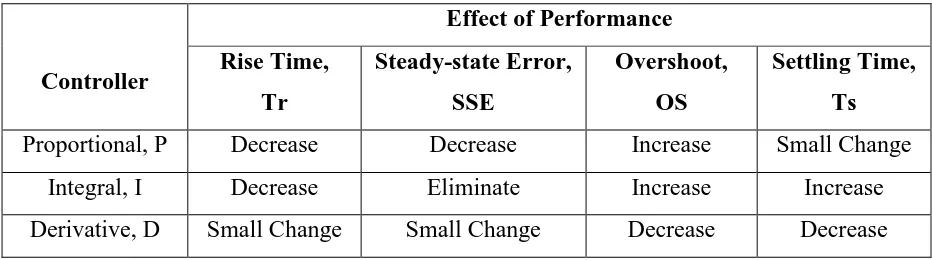
[image:22.612.80.546.520.650.2]In the PID controller, there are three parameters which needed to be tuned. One of the parameter was proportional gain, Kp in the proportional controller. This controller has the effect of reducing the rise time and steady-state error but the percentage of the overshoot in the system is high. In the integral controller, Ki as the integral gain, also decrease the rise time but it will eliminate the steady-state error of the system. Even though it eliminates the error but the percentage of the overshoot is increase and it will affect the settling time as well. In order to improve the performance of the system, derivative gain, Kd in the derivative controller is introduced. This controller will take action to improve the transient specification and stability of the system. The effects of the each of the controller on a closed-loop system are summarized in Table 2.1 shown below.
Table 2.1: PID controller properties
Controller
Effect of Performance Rise Time, Tr Steady-state Error, SSE Overshoot, OS Settling Time, Ts
Proportional, P Decrease Decrease Increase Small Change
Integral, I Decrease Eliminate Increase Increase
6
In order to gain the high stability and short transient response of the system, the correct gain value must be obtained from the PID tuning. Even though it is only three control parameters, but to adjust the parameter referred to the Table 2.1 are difficult. Therefore, an optimization tuning method of PID controller is used to determine the value of the gains.
2.1.2 Conventional Tuning Method of PID Controller
Tuning method is very important in control system. The values of the parameters in the controller can affect the performance of the system. The performance of the system can be generally improved by careful tuning but it also can be worst performance with poor tuning. In PID, there is several tuning method that can be used to find the desired control response.
2.1.2.1 Manual Tuning
Manual tuning is the easiest way to get the value of the parameter because no mathematical is required. However, the value of the parameter is not guaranteed as the best value because it is obtained by trial and error method. For a PID controller, the Ki and Kd values must be set first to zero before increasing the Kp. This will takes a lot of time to obtain the good result. The time can only be shortened with the experienced personnel.
2.1.2.2 Ziegler Nichols (Z-N)
7
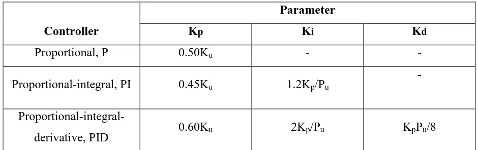
[image:24.612.78.548.223.371.2]the output of the loop starts to oscillate in the oscillation period, Pu in PID controller. The set gain is shown in Table 2.2 and Table 2.3. The advantage of this tuning rule is that it gives the PID loops best disturbance rejection but it yields an aggressive gain and overshoot in the system.
Table 2.2: Closed-loop Ziegler-Nichols method in PID Controller
Controller
Parameter
Kp Ki Kd
Proportional, P 0.50Ku - -
Proportional-integral, PI 0.45Ku 1.2Kp/Pu -
Proportional-integral-derivative, PID 0.60Ku 2Kp/Pu KpPu/8
Table 2.3: Open-loop Ziegler-Nichols method in PID Controller
Controller
Parameter
Kc Ti Td
Proportional, P Ko - -
Proportional-integral, PI 0.9Ko
3.3 τdead
-
Proportional-integral-derivative, PID 1.2Ko
2 τdead 0.5 τdead
[image:24.612.80.547.434.580.2]