4410
|
wileyonlinelibrary.com/journal/jace J Am Ceram Soc. 2019;102:4410–4414.1
|
INTRODUCTION
Glass is a ubiquitous material, used extensively in the ar-chitectural, automotive, aerospace, electronics, and chemis-try industries as a result of its transparency, esthetic appeal, chemical inertness, and interesting thermal and electrical properties. Flat glass is traditionally produced in sheet form via the float process whilst curved or customized shapes are cast in molds or are subtractively manufactured. The fab-rication of bespoke molds, however, increases production costs while subtractive manufacturing can be time consum-ing and in both cases the geometries achievable cannot be easily customized. Additive manufacturing (AM) is useful in this regard as it facilitates the production of complex shapes
without any prerequisite for molds and is cost effective when customization is important.1,2
Nevertheless, limited research has been conducted on AM of glass to date due to the challenges in glass processing. The high melting temperature of glass requires energy‐intensive manufac-turing procedures that create large temperature gradients within the built parts, generating residual stresses that can trigger ther-mal cracking. Additionally, the high transmittance in the visible and near‐infrared range of the electromagnetic spectrum impedes the processing of glass with lasers operating in this range while any microcracks or porosity introduced within the built struc-tures diminish their optical quality and lead to opaque surfaces.
The most promising AM methods for glass to‐date employ a composite mix of silica particles to create a “green” part, which
R A P I D C O M M U N I C A T I O N
Additive manufacturing of glass with laser powder bed fusion
Kyriaki Corinna Datsiou
1|
Ehab Saleh
1|
Fiona Spirrett
1|
Ruth Goodridge
1|
Ian Ashcroft
1|
Dave Eustice
21Centre for Additive Manufacturing, Faculty of Engineering, University of Nottingham, Nottingham, UK 2Glass Technology Services Ltd, Chapeltown, Sheffield, UK
Correspondence
Kyriaki Corinna Datsiou, Centre for Additive Manufacturing, Faculty of Engineering, University of Nottingham, Nottingham, UK.
Email: Kyriaki.Datsiou@nottingham.ac.uk
Funding information
Innovate UK, Grant/Award Number: 103447; Engineering and Physical Sciences Research Council, Grant/Award Number: EP/P027261/1
Abstract
Its transparency, esthetic appeal, chemical inertness, and electrical resistivity make glass an excellent candidate for small‐ and large‐scale applications in the chemical, electronics, automotive, aerospace, and architectural industries. Additive manufac-turing of glass has the potential to open new possibilities in design and reduce costs associated with manufacturing complex customized glass structures that are difficult to shape with traditional casting or subtractive methods. However, despite the sig-nificant progress in the additive manufacturing of metals, polymers, and ceramics, limited research has been undertaken on additive manufacturing of glass. In this study, a laser powder bed fusion method was developed for soda lime silica glass powder feedstock. Optimization of laser processing parameters was undertaken to define the processing window for creating three‐dimensional multilayer structures. These findings enable the formation of complex glass structures with micro‐ or mac-roscale resolution. Our study supports laser powder bed fusion as a promising method for the additive manufacturing of glass and may guide the formation of a new genera-tion of glass structures for a wide range of applicagenera-tions.
K E Y W O R D S
additive manufacturing, glass, lasers, powders, printing, soda‐lime‐silica
This is an open access article under the terms of the Creative Commons Attribution License, which permits use, distribution and reproduction in any medium, provided the original work is properly cited.
is thermally postprocessed to remove nonglass content. This ap-proach has been successfully applied in stereolithography3 and
direct ink writing,4 forming transparent and amorphous glass
parts. However, postprocessing results in volumetric shrinkage, which leads to deviations between design and actual dimensions.
Processing of pure glass feedstock has also been investi-gated, utilizing a number of AM methods with varying levels of success. Deposition of molten glass through a motor‐con-trolled nozzle resulted in transparent and esthetically pleasing parts intended for decorative applications.5 However, the
in-creased layer thickness poses limitations in resolution for its use in other applications. Soda lime silica, borosilicate glass, and fused quartz walls have been produced with filament fed approaches6‒9; however, manual feeding of the filament under
the laser beam restricted the process to elementary shapes with limited design freedom. Powder bed fusion methods have also been investigated for quartz,10,11 soda lime silica,12,13 and
borosilicate14 glass, but these mostly concentrated on the
for-mation of single layer scan tracks or basic multilayer forms. This paper focuses on the development of a laser pow-der bed fusion approach (LPBF, also known as selective laser melting) for soda lime silica glass within a commer-cially available system. The main aim is to demonstrate the potential of the laser powder bed fusion of glass powder in forming complex multilayer glass structures. Section 2 below describes the feedstock material and the manufacturing and postprocessing methods while salient results and conclusions are presented in Section 3 and 4 respectively.
2
|
EXPERIMENTAL DESCRIPTION
A soda lime silica (72SiO2‐14Na2O‐10CaO‐3MgO‐1Al2O3)
glass powder was used as feedstock material in this study. The powder is described by a Gaussian particle distribution with an average particle size of Dv,50 = 44 μm and bounds of
Dv,10 = 29 μm to Dv,90 = 66 μm as determined by laser
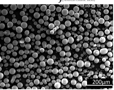
dif-fraction (Malvern, Mastersizer 3000, UK). This wide distri-bution denotes a good packing density; large amounts of fine particles reduce interparticle voids and provide a large surface area for laser processing. Additionally, the spherical particles of the powder (Figure 1) ensure adequate powder flowabil-ity. This was confirmed with a powder rheometer (Freeman technology, FT4 Powder Rheometer, USA), indicating a basic flowability energy (BFE) of 168 mJ and a marginally cohesive behavior, as indicated by a flowability rate index of (FRI) of 1.22, which can be attributed to the large amount of fine particles. UV‐VIS and FT‐IR tests identified an absorb-ance peak (A = 10.2 cm‐1) at 300 nm while an absorbance of
A = 0.4 cm‐1 was found at the standard wavelength used in
powder bed fusion (1064 nm) for bulk specimens of the same composition. Raw data for powder properties are available in the supplementary data file (Data S1).
The glass powder was processed in a commercial laser powder bed fusion system (ReaLizer GmbH SLM‐50, Germany). The system uses a fiber laser operating at a wavelength of 1064nm to selectively melt powder particles in layers of controlled thickness (glass transition tempera-ture of 575°C and melting temperatempera-ture of 1280°C were de-termined for the glass of this study by differential scanning calorimetry, Q600‐TA Instruments, USA). A thickness of 70 μm was selected in this study to accommodate the largest particle size. The laser trajectories are defined by the slices of a stl model, made at 70 μm intervals through its thick-ness. At the end of each increment, the platform displaces vertically to allow an additional layer of powder to be de-posited and the process is repeated to completion of the part. High purity (99.8%) alumina disks, of a thickness of 2.5 mm, were selected as substrates because of their good adhesion with glass and their high‐temperature resistance to thermal cracking. The temperature of the substrate was main-tained at 250°C during manufacturing to reduce the
tempera-ture gradients within the built parts while argon flow ensures inert conditions in the ReaLizer chamber.
Optimization of laser processing parameters (laser power, scan speed, and hatch spacing) was initially undertaken to determine the processing window for the formation of mul-tilayer structures. The 2d and 3d energy density ED ap-proaches (Equation 1a,b respectively) were used to populate process maps for thin walls (7 × 3 × w mm3 where w: the
width of a single laser scan track) and cubes (5 × 5 × 5 mm3) respectively.
where P: laser power (W), v: scan speed (mm/s), h: hatch spacing that is, the distance between adjacent laser scans (mm) and t: layer thickness (mm).
(1a,b)
ED= P
v⋅t and ED=
P
[image:2.595.309.548.40.229.2]v⋅h⋅t.
3
|
RESULTS AND DISCUSSION
The process maps for the thin walls and cubes (Figure 2A,B respectively) apply to the soda lime silica glass of this study and are divided in regions depending on the quality of the produced parts.For thin walls (Figure 2A), three regions are detected: (a) well‐defined walls of uniform thickness and height; (b) partly consolidated walls that lack uniform height and; (c) combi-nations of processing parameters that could not consolidate the glass powder. Uniformity of wall height and thickness were respectively assessed qualitatively and quantitatively with optical microscopy; two specimens were analyzed per combination of parameters to ensure repeatability taking 10 equidistant readings per specimen for wall thickness. The thickness reported below is the average of the two specimens and is considered uniform when the coefficient of variation is below 10% for each specimen.
High‐quality thin walls were found to be formed for en-ergy densities exceeding ED ≥ 27 J/mm2. The thin walls of
this study were produced by repetition of a single laser scan
in each layer; their thickness is, therefore, directly related to melt pool width, w, and this can provide insight on the resolution achievable for more complex structures produced through laser powder bed fusion. It was found that wall thick-ness was linearly proportional to the selected energy density and empirically follows Equation 2, while the minimum wall thickness that could be successfully achieved was 385 μm.
Cubic structures were at first assessed qualitatively to de-fine the energy density limits for successful material consoli-dation and distinguish well‐defined parts: the lower limit was determined by parts that failed/cracked during the manufac-turing process or their retrieval from the substrate while the upper limit was determined by parts that showed excessive track height/spheroidization in their center due to surface ten-sion in the molten glass. Subsequently, quantitative analysis of the geometric accuracy followed up for the well‐defined parts with Micro‐CT imaging (ZEISS, XRADIA Versa XRM – 500, Germany) in slices of 4 μm thickness throughout the 5‐mm height and image processing using the open source software ImageJ.15
It is found that cubic structures could be successfully pro-duced for energy densities ranging between 80 ≥ ED ≥ 110 J/ mm3 (Figure 2B). Energy densities below this range resulted
in brittle and poorly consolidated parts while energy densities above the maximum limit of this range led to excessive track height as previously described which impeded deposition of subsequent powder layers and thus, the completion of the AM process. The geometric accuracy of the average surface area of the Micro‐CT slices (i.e., the difference between the design area and the actual area) was below 6% for all well‐de-fined samples. The slight increase in surface area is attributed to unfused powder particles that adhere to the specimen.
Figure 2A,B provide useful information for manufacturing thin‐walled or large surface area structures respectively, that have designs similar to the ones described above. Significant deviations from those for example, combinations of thin‐ walled and large surface area features within the same struc-ture or strucstruc-tures with significantly large surface areas might require further fine‐tuning of laser processing for example, multiple combinations of processing parameters within the same structure or optimization of laser scan strategies.
It should be noted here that the above process maps are developed for the soda lime silica glass powder of this study. Changes in particle size of the feedstock material will not change the required energy densities for material consoli-dation even when different combinations of parameters will have to be selected to accommodate the new layer thickness. However, different feedstock compositions and, therefore, material properties will lead to changes in the required en-ergy density.
(2)
[image:3.595.48.289.349.690.2]w=0.00082⋅ED+0.1597(mm)
The next section demonstrates how the optimized pro-cessing parameters can be used to form complex structures that would not be achievable with standard glass process-ing methods. Lattice structures, designed from the previous trials using the in‐house software Flatt_Pack,16 were
suc-cessfully produced in different configurations. Examples of 10 × 10 × 10 mm3 BCC, gyroid matrix, gyroid network,
and diamond network lattices are shown in Figure 3B. These structures can be also scaled up to suit different applications for example, the 20 × 20 × 20 mm3 gyroid network lattice
shown in Figure 3C. Such structures are finding increasing ac-ademic interest and industrial application due to their unique properties for example, lightweight nature, high surface to volume ratio and energy‐absorbing properties. Additionally, AM of lattice structures enables the control of cell geometry, grading, and conformance to external geometries not achiev-able with any other manufacturing method.16‒18 However, to
date these structures have been made from metal, polymer, or ceramic processing methods. This is the first demonstration that such structures can be generated from the selective laser melting of glass powder. The distinct properties of glass can open up new fields of application for these structures.
Complex AM structures have been previously demon-strated for ceramics.19,20 However, the main advantage of the
LPBF method presented in this paper over AM methods com-monly used for ceramics is the processing of pure feedstock material. Most AM methods for ceramics are indirect, involv-ing binders to form a composite “green” part, followed by postmanufacturing heat treatment to remove binder content and sintering to densify the part. Pure ceramic feedstock has also been used in LPBF. However, parts of high complex-ity similar to the ones described in this paper have not been demonstrated.21,22
Scanning electron microscopy (SEM) inspection demon-strated material consolidation in the built parts (Figure 3A) while partially fused powder particles could be observed on the lattice walls. X‐ray diffraction (Bruker, D8 ADVANCE, USA) confirmed that the glass remained amorphous after laser processing (graph available in supplementary Data S1). The micro‐CT slices were additionally analyzed in ImageJ15
to assess the internal porosity which marginally decreased with increased energy density; average porosities of 12.1% and 11.3% were respectively reported for energy densities of 78.5 and 107.1 J/mm3 which correspond to the energy
den-sity limits of the “well defined” region in Figure 2B. The opaque appearance of the built parts can be jointly at-tributed to porosity and partially fused powder particles on the outer surface of the parts. Postprocessing of the built parts by heat treatment at 650°C for 5 hours can improve translucency
[image:4.595.219.547.47.280.2]whilst retaining part shape. However, this is accompanied by fur-ther material consolidation and, fur-therefore, volumetric shrinkage. The above findings can form the basis for tailoring laser powder bed fusion and postprocessing methods to suit partic-ular applications for example, partially fused powder particles could act as baffles in micro‐fluidic channels; an example of a fully enclosed channel produced with laser powder bed fusion are shown in Figure 3D with minimum permissible internal diameters of 1.1 mm. Additionally, highly porous glass struc-tures with large surface to volume ratios could prove useful as structured catalysts in chemistry or scaffolds in tissue engi-neering, even in opaque forms, while smooth and translucent/ transparent glass structures could be preferable in decorative applications. Tailoring of powder bed fusion method can be achieved by performing further investigations, similar to those described in this study on various glass compositions that would suit particular applications based on their properties.
FIGURE 3 Glass structures produced with powder bed fusion: (A) Grid structure and SEM micrograph showing powder consolidation and partially fused powder particles on lattice walls; (B) various 10 × 10 × 10 mm3 lattice structures (2 cells/axis); (C) 20 × 20 × 20 mm3 Gyroid network lattice structure (4 cells/axis) and; (D) flow reactor channel with a length of 10mm and an internal diameter of 2 mm [Colour figure can be viewed at wileyonlinelibrary.com]
(A) (B)
4
|
CONCLUSIONS
This paper successfully demonstrated the potential of a laser powder bed fusion approach to form glass structures with high levels of complexity in design that cannot be achieved with standard glass‐forming methods. Process maps were populated for the formation of thin walls and solid cubes, which can be used as a guide for the formation of any small‐ scale glass structure. This study may open possibilities for a wide range of applications from chemistry and biomedical to decorative glass industries.
ACKNOWLEDGMENTS
Financial support from Innovate UK (project number 103447) and the Engineering and Physical Sciences Research Council (grant number EP/P027261/1) is gratefully acknowl-edged. The authors would also like to thank the Nanoscale and Microscale Research Centre (NMRC) for providing ac-cess to SEM instrumentation.
ORCID
Kyriaki Corinna Datsiou https://orcid. org/0000-0002-6672-535X
REFERENCES
1. Atzeni E, Iuliano L, Minetola P, Salmi A. Redesign and cost es-timation of rapid manufactured plastic parts. Rapid Prototyp J. 2010;16(5):308–17.
2. Atzeni E, Salmi A. Economics of additive manufacturing for end‐us-able metal parts. Int J Adv Manuf Technol. 2012;62(9–12):1147–55. 3. Kotz F, Arnold K, Bauer W, Schild D, Keller N, Sachsenheimer K,
et al. Three‐dimensional printing of transparent fused silica glass. Nature. 2017;544(7650):337–9.
4. Nguyen DT, Meyers C, Yee TD, Dudukovic NA, Destino JF, Zhu C, et al. 3D‐printed transparent glass. Adv Mater. 2017;29(26):1–5. 5. Klein J. Additive manufacturing of optically transparent glass.
Master’s thesis, Massachusetts Institute of Technology (MIT); 2015. 6. Luo J, Pan H, Kinzel EC. Additive manufacturing of glass. J Manuf
Sci Eng. 2014;136(6):061024.
7. Luo J, Gilbert LJ, Peters DC, Bristow DA, Landers RG, Goldstein JT, et al. Bubble formation in additive manufacturing of borosili-cate glassIn: Proceedings of the 27th International Solid Freeform Fabrication Symposium. 2016:998–1003.
8. Luo J, Gilbert LJ, Qu C, Landers RG, Bristow DA, Kinzel EC. Additive manufacturing of transparent soda‐lime glass using a fila-ment‐fed process. J Manuf Sci Eng. 2017;139(6):061006. 9. Luo J, Gilbert LJ, Bristow DA, Landers RG, Goldstein JT, Urbas
AM, et al. Additive manufacturing of glass for optical applications. In: Laser 3D Manufacturing III. 2016:1–9.
10. Khmyrov RS, Grigoriev SN, Okunkova AA, Gusarov AV. On the possibility of selective laser melting of quartz glass. Phys Procedia. 2014;56:345–56.
11. Khmyrov RS, Protasov CE, Grigoriev SN, Gusarov AV. Crack‐free selective laser melting of silica glass: single beads and monolayers on the substrate of the same material. Int J Adv Manuf Technol. 2016;85:1461–9.
12. Fateri M, Gebhardt A. Jewelry fabrication via selective laser melt-ing of glass. In: Proceedmelt-ings of the ASME 2014 12th Biennial Conference on Engineering Systems Design and Analysis (ESDA2014). 2014.
13. Fateri M, Gebhardt A. Selective laser melting of soda‐lime glass powder. Int J Appl Ceram Technol. 2015;12(1):53–61.
14. Klocke F, McClung A, Ader C.Direct laser sintering of borosil-icate glass. In: Proceddings of the International Solid Freeform Fabrication Symposium. 2004:214–9.
15. Rasband W. ImageJ [Internet]. Bethesda, MD: National Institutes of Health. Available from: https://imagej.nih.gov/ij/
16. Maskery I, Aremu AO, Parry L, Wildman RD, Tuck CJ, Ashcroft IA. Effective design and simulation of surface‐based lattice struc-tures featuring volume fraction and cell type grading. Mater Des. 2018;155:220–32.
17. Aremu Ao, Brennan‐Craddock J, Panesar A, Ashcroft Ia, Hague R, Wildman Rd, et al. A voxel‐based method of constructing and skin-ning conformal and functionally graded lattice structures suitable for additive manufacturing. Addit Manuf. 2017;13:1–13.
18. Panesar A, Abdi M, Hickman D, Ashcroft I. Strategies for func-tionally graded lattice structures derived using topology optimisa-tion for Additive Manufacturing. Addit Manuf. 2018;19:81–94. 19. Schwentenwein M, Homa J. Additive manufacturing of dense
alu-mina ceramics. Int J ofApplied Ceram Technol. 2015;12(1):1–7. 20. Duan B, Wang M, You W, Lam W, Yang Z, Lu WW. Three‐
dimensional nanocomposite scaffolds fabricated via se-lective laser sintering for bone tissue engineering. Acta Biomaterialia. 2010;6(12):4495–505. https://doi.org/10.1016/j. actbio.2010.06.024.
21. Bertrand P, Bayle F, Combe C, Goeuriot P, Smurov I. Ceramic components manufacturing by selective laser sintering. Appl Surf Sci. 2007;254:989–92.
22. Wilkes J, Hagedorn YC, Meiners W, Wissenbach K, Wilkes J, Hagedorn Y, et al. Additive manufacturing of ZrO2 ‐Al2O3 ce-ramic components by selective laser melting. Rapid Prototyp J. 2013;19(1):51–7.
SUPPORTING INFORMATION
Additional supporting information may be found online in the Supporting Information section at the end of the article.
![FIGURE 2 Process maps for the formation of: (A) thin walls (7 × 3 × w mm3) and; (B) cubes (5 × 5 × 5 mm3) [Colour figure can be viewed at wileyonlinelibrary.com]](https://thumb-us.123doks.com/thumbv2/123dok_us/1817934.137349/3.595.48.289.349.690/figure-process-formation-walls-colour-figure-viewed-wileyonlinelibrary.webp)
![FIGURE 3 Glass structures produced with powder bed fusion: (A) Grid structure and SEM micrograph showing powder consolidation and partially fused powder particles on lattice walls; (B) various 10 × 10 × 10 mmnetwork lattice structure (4 cells/axis) and; (D) flow reactor channel with a length of 10mm and an internal diameter of 2 mm [Colour figure can be viewed at 3 lattice structures (2 cells/axis); (C) 20 × 20 × 20 mm3 Gyroid wileyonlinelibrary.com]](https://thumb-us.123doks.com/thumbv2/123dok_us/1817934.137349/4.595.219.547.47.280/structures-micrograph-consolidation-partially-particles-structure-structures-wileyonlinelibrary.webp)
