Int. J. Electrochem. Sci., 14 (2019) 7516 – 7528, doi: 10.20964/2019.08.36
International Journal of
ELECTROCHEMICAL
SCIENCE
www.electrochemsci.org
Electrochemical Oxidation of Aniline in Sodium Chloride
Solution Using a Ti/RuO
2Anode
Xu Zhu1, Weiwu Hu2,1,*, Chuanping Feng1, Hongyan Chen3,Nan Chen1, and Rui Li1
1 School of Water Resources and Environment, China University of Geosciences (Beijing), No.29 Xueyuan Road. Haidian District, Beijing 100083, China
2 The Center of Journal, China University of Geosciences (Beijing), No.29 Xueyuan Road. Haidian District, Beijing 100083, China
3 College of Science, Beijing Forestry University, No.35 Tsinghua East Road. Haidian District, Beijing 100083, China
*E-mail: [email protected]
Received: 5 April 2019 / Accepted: 26 May 2019 / Published: 30 June 2019
The degradation of aniline by electrochemical oxidation process using Ti/RuO2 anode has been studied under different operating conditions. Compared with the result conducted without Cl-, aniline removal rate increased sharply when using NaCl as the electrolyte for the electro generation of active chlorine. Researches showed that the removal rate of aniline and COD increased with the increase of NaCl concentration, current density, initial pH and plate distance. Aniline was removed completely and quickly in less than 25 min while the mineralization efficiency achieved 75.11%. The result of the research showed that Cl- was an excellent agent in electrochemical oxidation degradation of aniline when using Ti/RuO2 as the anode.
Keywords: Aniline, Electrochemical oxidation, Ti/RuO2 anode, active chlorine
1. INTRODUCTION
aniline into the environment reached 30,000 tons per year [2]. Therefore, wastewater containing aniline must be disposed strictly and efficiently.
Many techniques such as biodegradation [9, 11], physicochemical adsorption methods [2, 12], supercritical water oxidation [13], ozonation [14], chemical method [15-17] and electrochemical oxidation [18, 19] have been used to remove aniline from some domestic and industrial wastewaters. All these treatments present different problems with efficiency, cost or feasibility [3]. Biological processes are cost-effective and have been well studied for waste-water treatment. However, they are limited by the microbial activity especially in the degradation of toxic and refractory organic pollutants and always suffer from long reaction time. Physical adsorption methods can transfer pollutants from waste-water to another medium easily, which may lead to secondary pollution, and the adsorption material is hard to regenerate. Chemical methods can treat aniline efficiently, but always consume more energy or chemicals such as H2O2 and Fe2+, and supercritical water oxidation method has higher demand on the quality of reactors [20, 21]. Furthermore, they always need to post-treatment and cause secondary pollution [22].
Scientists have focused on using electrochemical process to treat organic waste-water [23]. Electrochemical oxidation belongs to advanced oxidation processes (AOPs), in which hydroxyl radical is generated [24, 25]. Hydroxyl radical has the second highest redox potential (2.8 eV) after fluorine (2.87 eV). Generally, it is a nonselective oxidant, and it can react more easily with compounds that have unsaturated bonds like aromatic hydrocarbons [26]. Electrochemical oxidation process is regarded as a more efficient method to treat organic pollutants and have the advantage of simple setup, easy control, and no chemicals are needed before and after treatment [27]. Besides, they are environmentally friendly and economically [28]. Varies anodes have been investigated to degrade aniline, such as BDD [29], Ti/SnO2-Sb2O3-PtO [30], Ti/SnO2 [31] and so forth. During electrolysis process, adsorbed hydroxyl radicals is generated at anode surface from water discharge by Eq 1.
MO𝑥+ H2O → MO𝑥(∙ OH) + H++ 𝑒− (1)
In these study, aniline was degraded fast through ·OH generated on the surface of anode material. However, some anions such as chlorine ion and carbonate exist commonly in nature wastewater would act as hydroxyl radical scavenger via Eq 2-3 to impact the removal of organic pollutants in electrolysis process [32-34].
∙ OH + Cl−→ HClO (2)
∙ OH + CO32− ↔ CO3∙−+ OH− (3)
However, active chlorine, which includes Cl2, HClO and OCl-, generated from direct and indirect oxidation of Cl- would also have the oxidation ability to degrade organic pollutants [2, 35-37]. Researchers have focused on the performance of chlorine ion in electrochemical oxidation process [37, 38].
RuO2 is an excellent electro-catalysis transitional metal oxide possessing rutile structure, has considerable electrocatalytic activity in chlorine evolution reaction [39] and has been used frequently as anode for industrial to produce chlorine [40]. So it has potential applications in all branches of electrochemistry, especially in dimensionally stable anode [41].
several operating parameters such as NaCl concentration, current density, initial pH and plate distance on removal efficiency of aniline, chemical oxygen demand (COD) and instantaneous current efficiency (ICE) were studied to get the optimized operation conditions.
2. EXPERIMENTAL
2.1 Materials and reagents
Ti/RuO2 anode was purchased from Baoji Yichen anode co. ltd. Aniline was purchased from Fuchen chemical reagent co. LTD. Initial pH was adjusted with 0.1 M H2SO4 and 0.1 M NaOH. All the other chemicals used in the study were of analytical grade and diluted with ultrapure water.
2.2 Apparatus and analytical procedures
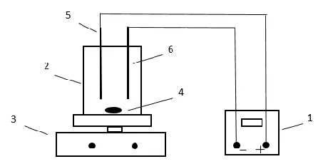
[image:3.596.184.414.435.550.2]Experiments were carried out in batch mode in a cylindrical, undivided acrylic electrolysis cell with a volume of 700 ml (diameter: 10 cm; height: 10 cm) under vigorous stirring by a magnetic stir bar. Ti/RuO2 anode and Cu/Zn alloy plate cathode were installed in the reactor parallelly, the effective working area was 42.75 cm2. The current was provided by a PS-305 DC power supply. The schematic diagram of the electrolysis apparatus was shown in Fig. 1.
Figure 1. Schematic diagram of the reactors. 1 – power supply, 2 – electrolysis cell, 3 – the magnetic stirrer, 4 – magnetic stir bar, 5 – Ti/RuO2 anode, 6 – Cu/Zn alloy cathode.
Linear sweep voltammetry (LSV) measurements were conducted in a conventional three-electrode system with a scan rate of 10 mV/s and a step potential of 1 mV at room temperature in NaCl solution. The concentration of hydroxyl radicals generated was monitored with RF-5301PC spectrofluorophotometer. Active chlorine was measured by potentiometer titration with potassium iodide. Samples were extracted periodically from the reaction cell to analyze the variation of aniline and COD concentration [42]. The instantaneous current efficiency (ICE) was calculated using Eq 4.
ICE =(COD𝑡−COD𝑡+∆𝑡)
Where CODt and CODΔt are the chemical oxygen demand (g/L) at time t and t + ∆t (s), I is the current (A), F is the Faraday constant (996,487 C mol-1), V is the electrolyte volume (L), 8 is the oxygen equivalent mass (8 eq-1).
The degradation rate of aniline and COD were described in pseudo first-order kinetics mechanism as shown in Eq 5.
ln (𝐶0
𝐶𝑡) = 𝑘𝑡 (5)
Where C0 and Ct is the initial concentration of aniline and COD (mg/L) and at time t (min), k is the pseudo-first-order rate constant.
3. RESULTS AND DISCUSSION
[image:4.596.199.400.458.613.2]3.1 Linear sweep voltammetry experiment
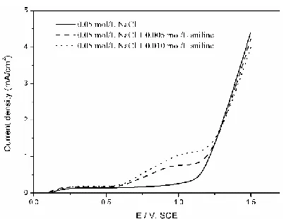
Fig. 2 shows the linear sweep voltammograms recorded with the Ti/RuO2 anode in the presence and absence of aniline. The chlorine evolution potential was 1.158 V. The current density increased with the increase of aniline concentration before chlorine evolution potential, suggesting the direct oxidation of aniline occurred on Ti/RuO2 surface. In the apparent chlorine evolution phase, current density decreased with the increase of aniline concentration, it might be due to the generation of some intermediate products such as malic acid and polyaniline [30] which would be absorbed on anode surface and inhibit the transfer of electrons.
Figure 2. LSV curves for Ti/RuO2 anode in 0.05 mol/L NaCl solution and after the addition of 0.005 and 0.010 mol/L aniline. Scan rate: 0.01V/s.
3.2 The generation of hydroxyl radical
section, the generation of hydroxyl radical in 1 g/L Na2SO4 and 1 g/L NaCl solution at different pH was studied.
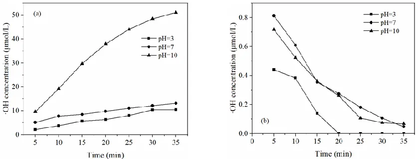
Fig. 3(a) shows that ·OH generated when electrolysis conducted in Na2SO4 solution and the generation rate was higher in alkaline than that in acid and neutral condition. Meanwhile, it means that at least a part of ·OH was adsorbed at the anode surface physically, which was different from Gaudet [43]. Fig. 3(b) shows that the concentration of ·OH detected was very low when electrolysis conducted in NaCl solution than that in Na2SO4 solution. It may be because ·OH generated can react with Cl- via reaction (2) and the direct oxidation of Cl- at anode competed with water discharge reaction.
Figure 3. Change of ·OH in (a) 1 g/L Na2SO4 and (b) 1 g/L NaCl with electrolysis time at pH value 3, 7 and 10. Current density 20 mA/cm2, plate distance 1 cm.
According to Comninellis, hydroxyl radicals absorbed on anode surface physically or chemically, expressed as MOx(·OH) and MOx+1 [44]. When electrolysis process conducted in NaCl solution, organics would be oxidized through Eq 6-8 simultaneously [45].
MOx(∙ OH) + R → CO2+ H2O (6)
MOx+1+ R → MOx+ RO (7)
ClO−+ R → Cl−+ RO (8)
3.3 Effect of NaCl concentration
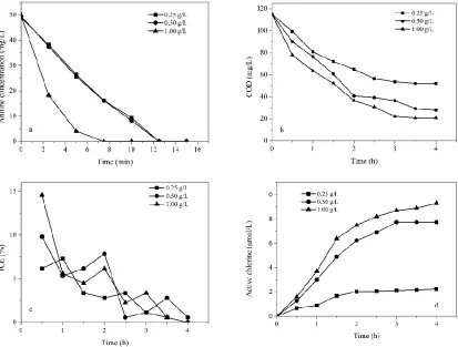
Active chlorine generated in electrochemical oxidation process has a strong oxidation ability on organic. Therefore, the influence of NaCl concentration on the degradation of organic pollutants has been studied during the last decades [46, 47]. In this study, NaCl concentration was set at 0.25, 0.50 and 1.00 g/L to evaluate the influence of NaCl concentration on the degradation of aniline.
[image:5.596.90.510.238.398.2][image:6.596.94.507.171.484.2]
shown in Table 1. The removal rate was concentration-dependent which was in accordance with the previous studies [48]. COD got the biggest removal efficiency of 82.6 % when NaCl concentration was 1.00 g/L at 3 h and COD concentration was no more decrease with time, it was due to some carboxylic acid and other micromolecular organics generated.
Figure 4. Influence of NaCl concentration on (a) aniline, (b) COD, (c) instantaneous current efficiency and (d) active chlorine. Current density 20 mA/cm2, initial pH value 3.0, plate distance 1 cm.
Compare with the study using Na2SO4 as electrolyte, the incineration rate of aniline was promoted.Brillas and Mur studied the electrochemical oxidation of aniline using a Ti/Pt/PbO2 anode and a Pt anode, respectively, in 7.1 g Na2SO4 electrolyte with the current density of 20 mA/cm2, they found that less than 25% TOC was removed after 6 h electrolysis [49]. RuO2/IrO2 was applied to degrade aniline in the electro-Fenton process, more than 95% aniline was removed in less than 30 min while only 45% COD was removed [50]. These results indicated that the presence of Cl- in electrolyte would promote the degradation of aniline and COD gravely. This was consistent with the results observed in this study that ·OH was no longer the main oxidant in NaCl solution.
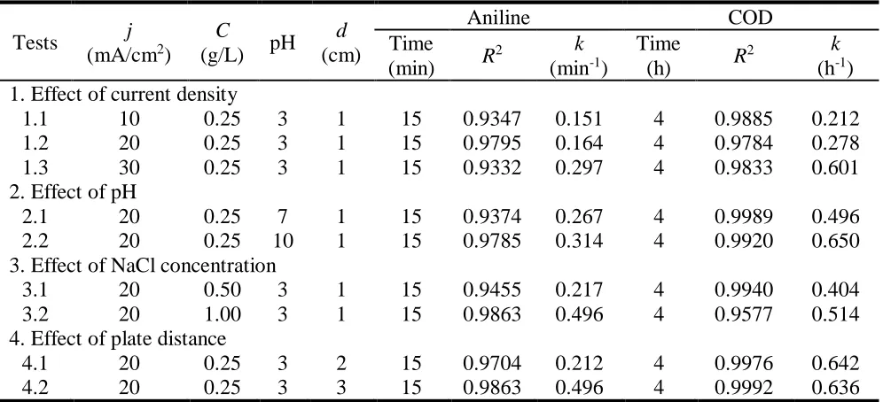
Table 1. Electrochemical oxidation of aniline using Ti/RuO2 anode under various conditions
Tests j
(mA/cm2) C
(g/L) pH d (cm)
Aniline COD
Time (min) R
2 k (min-1)
Time
(h) R
2 k (h-1) 1. Effect of current density
1.1 10 0.25 3 1 15 0.9347 0.151 4 0.9885 0.212
1.2 20 0.25 3 1 15 0.9795 0.164 4 0.9784 0.278
1.3 30 0.25 3 1 15 0.9332 0.297 4 0.9833 0.601
2. Effect of pH
2.1 20 0.25 7 1 15 0.9374 0.267 4 0.9989 0.496
2.2 20 0.25 10 1 15 0.9785 0.314 4 0.9920 0.650
3. Effect of NaCl concentration
3.1 20 0.50 3 1 15 0.9455 0.217 4 0.9940 0.404
3.2 20 1.00 3 1 15 0.9863 0.496 4 0.9577 0.514
4. Effect of plate distance
4.1 20 0.25 3 2 15 0.9704 0.212 4 0.9976 0.642
4.2 20 0.25 3 3 15 0.9863 0.496 4 0.9992 0.636
All the tests were operated at room temperature and the initial aniline concentration was 50 mg/L.
j: Current density.
C: Initial concentration of NaCl. k: Degradation rate constant. R2: The regression coefficients.
The cell voltage and the chlorine evolution potential would decrease with the increase of NaCl concentration [52]. It means that the oxygen evolution reaction was restrained and more current was consumed in the generation of chlorine. Additionally, active chlorine is easier to disperse into the electrolyte solution to react with organic pollutants. So it can be seen from Fig. 4(c), the increase of aniline and COD removal rate were observed when NaCl concentration was increased and so as to ICE.
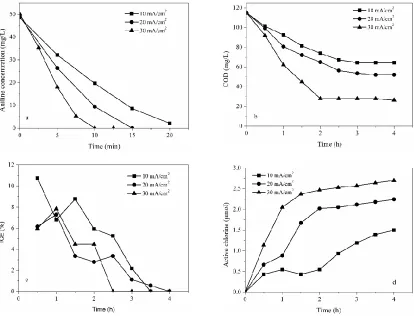
3.4 Effect of current density
higher than 0.93. It showed that the k value increased from 0.151 to 0.297 min-1 for aniline and from 0.212 to 0.601 h-1 for COD removal rate with the increase of current density from 10 to 30 mA/cm2.
DSA anodes give rise to higher current efficiency for the formation of active chlorine [54]. The increase of current density would increase the migration rate of Cl- and cell voltage that promote the generation of active chlorine and the concentration of active chlorine at a fixed amount of circulated charge was dramatically high [51, 55]. As shown in Fig. 5(d), active chlorine concentration increased apparently with the increase of current density. In the absence of Cl-, electrochemical oxidation process of RuO2 anode was studied and a positive effect of higher current density was also discovered [56]. It means that the increase of current density would promote the removal rate of aniline and COD by ·OH and anodic direct oxidation.
Figure 5. Influence of different current density on (a) aniline, (b) COD, (c) the instantaneous current efficiency and (d) the generation of active chlorine. NaCl concentration 0.25 g/L, initial pH value 3.0, plate distance 1 cm.
[image:8.596.93.507.272.588.2]
at anode accelerated and consequently promoted the generation of active chlorine. However, influence by mass transfer efficiency, organic and Cl- concentration would be much lower near anode surface than other places [57], and oxygen evolution deputy reaction aggravated, as shown in Eq 9-10.
2MOx(∙ OH) → 2MOx+ O2+ 2H++ 2𝑒− (9)
2MOx+1 → 2MOx+ O2 (10)
This result was the same as other researchers in degrading different organics [23, 53, 58]. Based on Joule’s law, the increase of current density would increase the heat production exponentially, which means that the ICE would be greatly reduced. Meanwhile, the oxygen evolution side reaction would be promoted and consume more energy at higher current density, so the ICE value was lower than at low current density [23]. Interestingly, a higher current density, due to the violent gas generation reaction, it was not easy for intermediates to adsorb on the electrode, so the reduction of electrode passivation seemed to be able to improve ICE as well as compensation of the ICE loss at high current density. As a result, the ICE value didn’t show apparent decrease followed by an increase when current densities were 20 and 30 mA/cm2.
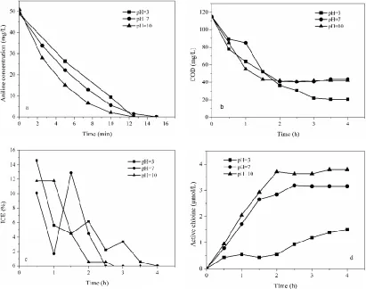
3.5 Effect of initial pH
The pH plays an important part in the electrochemical oxidation of organic pollutants. Initial pH was adjusted to 3, 7 and 10 to study aniline degradation as shown in Table 1 and Fig. 6. From Fig 6a and Fig. 6(b), the removal rate of both aniline and COD were improved with the increase of pH value from 3 to 10 and the k value increased from 0.164 to 0.314 (min-1) for aniline and from 0.278 to 0.650 (h-1) for COD removal rate. Aniline was completely removed in less than 15 min at pH = 3 for which the removal rate was the minimum. 64.7% COD was removed after 2.5 h electrolysis at pH = 7 and 10, which were lower than that conducted at pH = 3.
Hydroxyl radicals are easier produced in alkaline solution [59], therefore promote the generation of active chlorine from Eq 2 [37, 60], the concentration of active chlorine in different pH is shown in Fig. 6(d). Therefore, the removal rate of aniline and TOC was higher in alkaline solution than that in neutral and acidic solutions.
According to some studies on the kinetics of gaseous chlorine in water treatment, component contents of active chlorine was variable when the pH was changed. Gaseous Cl2 hydrolysis is nearly completely at pH < 2 and HOCl is the main component at 2 < pH < 6, when the pH range from 6 - 9, HClO and ClO- are the main active chlorine species, when pH > 9, the main species is ClO- [61, 62]. Meanwhile, in alkaline solutions, ClO3- would be accumulated (Eq 11 and Eq 12) [63]. Cl2 and HClO are more effective oxidation medium than its ionized counterpart ClO- [38, 64]. So the removal ratio of COD was higher in acidic solution. This result also attributed to the electrochemical production of H2O2 at the cathode in alkaline solution (Eq 13) [65]. Therefore, aniline and COD got the biggest removal rate at initial pH = 10.
6OCl−+ 3H2O → 2ClO3−+ 4Cl−+ 6H− (11)
OCl−+ 2HClO → ClO 3
−+ 2HCl (12)
O2+ 2H++ 2e− → H
Figure 6. Influence of initial pH on (a) aniline, (b) COD, (c) instantaneous current efficiency and (d) the generation of active chlorine. NaCl concentration 1.0 g/L, current density 20 mA/cm2, plate distance 1 cm.
Fig. 6(c) shows the ICE during the electrolysis process. Compared with alkaline and neutral solution, ICE was higher in acidic solution in the initial stage. It was because the oxygen evolution potential was higher in acidic solution in acidic solution than that in neutral and alkaline solution. Therefore, more energy was consumed in the oxidation of organic and the current efficiency increased. In the group pH = 7, H2 evolution reaction at cathode, solution pH increased and promoted the generation of active chlorine and then ICE increased at 1.5 h.
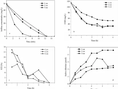
3.6 Effect of plates distance
The influence of different plate distance on electrochemical oxidation degradation of aniline was studied. As shown in Fig. 7(a), 7(b) and Table 1, aniline was completely removed in 15 min and the k values were 0.212 and 0.496 min-1 when the plate distance were 2 and 3 cm, respectively, much higher than that conducted at 1 cm (k = 0.164 min-1). The COD removal efficiency were 69.26% and 70.35%, respectively, after 3 h electrolysis when the plate distance were 2 cm (k = 0.636 h-1) and 3 cm (k = 0.642 h-1), which were much higher than that conducted when the plate distance was 1 cm.
[image:11.596.90.503.190.500.2]
fiercely. When plates distance increased from 1 cm to 2 cm, cell voltage increased from 21.6 V to 23.0 V, which promoted the direct oxidation reaction and active chlorine generation as shown in Fig. 7(d). However, when plates distance was 3 cm, cell voltage increased from 23.0 V to 45.7 V, more energy was consumed in the oxygen evolution side reaction and heat generation. Hence, when plate distance was 2 cm, the degradation process got the best removal rate and removal efficiency as shown in Fig. 7(c).
Figure 7. Influence of initial pH on (a) aniline, (b) COD, (c) instantaneous current efficiency and (d) the generation of active chlorine. NaCl concentration 0.25 g/L, current density 20 mA/cm2, pH value 3.0.
4. CONCLUSION
The results of the present study have clearly demonstrated that Ti/RuO2 anode was an efficient electrode in electrochemical oxidation of aniline in the presence of chloride ion for the generation of active chlorine. The conclusion can be drawn as follows:
(1) In NaCl solution, aniline and COD were removed through anodic direct oxidation and indirect oxidation by active chlorine. And the removal rate of aniline was much higher than that absence of Cl-.
(2) Higher Cl- concentration and current density, appropriate plate distance (2 cm) and in acidic solution had a positive effect on the removal of aniline and COD.
concentration of chloride ion.
For the first time, this study systematically assessed the effect of typical electrochemicall operating parameters on the electrochemical oxidation process using Ti/RuO2 anode in chloride-containing solution for the actual application of electrochemical technology in the rapid and efficient treatment of aniline wastewater.
References
1. E.M. Bomhard. Arch. Toxicol, 77(2003) 291.
2. W. Xiao, P. Zhou, X. Mao, D. Wang, J. Mater. Chem. A., 3 (2015) 8676.
3. A. Benito, A. Penadés, J.L. Lliberia. R. Gonzalez-Olmos, Chemosphere, 166(2017) 230. 4. G. Emtiazi, S. Mohamad, M. Fatemeh, Water Res., 35 (2001) 1219.
5. X. Zhang, J. Song, W. Ji, N. Xu, N. Gao, X. Zhang, H. Yu, J. Mater. Chema. A., 37(2015) 18953. 6. N. Tao, G. Liu, L. Bai, L. Tang, C. Guo, Chemosphere, 169(2017) 467.
7. Y. Wu, X. Xiao, C. Xu, D. Cao, D. Du, Appl. Microbiol. Biotechnol., 97(2013) 7439-7446. 8. R. Hu, X. Wang, S. Dai, D. Shao, T. Hayat, A. Alsaedi, Chem. Eng. J., 260(2015) 469. 9. R.C. Wyndham, Appl. Environ. Microb., 51(1986) 781.
10.Z. Liu, H. Yang, Z. Huang, P. Zhou, S.J. Liu, Appl. Microbiol. Biotechnol., 58 (2002) 679. 11.J. Qiong, Z. Hu, Z. Jin, L. Qiu, W. Zhong, Z. Pan, Bioresour. Technol., 117(2012) 148. 12.A.J. Jadhav, V.C. Srivastava, Chem. Eng. J., 229(2013) 450.
13.H. Ma, S. Wang, L. Zhou, Y. Gong, D. Xu, Y. Wang, Y. Guo, Y. Ind. Eng. Chem. Res., 51(2012) 9475.
14.J. Sarasa, S. Cortés, P. Ormad, R. Gracia, J.L. Ovelleiro, Water Res., 36(2002) 3035.
15.H.T. Gomes, P. Selvam, S.E. Dapurkar, J.L. Figueiredo, J.L. Faria, Microporous. Mesoporous. Mater., 86 (2005) 287.
16.G. Ersöz, S. Atalay, J. Environ. Manage., 113(2012) 244.
17.C. Su, E.D. Pagaling, G.L. Peralta, M, C. Lu, Environ. Prog. Sustainable Energy, 33 (2014) 410. 18.F. Cases, F. Huerta, P. Garcés, E. Morallón, J.L. Vázquez, J. Electroanal. Chem., 501(2001) 186. 19.M. Mitadera, N. Spataru, A. Fujishima, J. Appl. Electrochem., 34(2004) 249.
20.J. Garcia, H.T. Gomes, P. Serp, P. Kalck, J.L. Figueiredo, J.L. Faria, Carbon, 44 (2006) 2384. 21.H.T. Gomes, B.F. Machado, A. Ribeiro, I. Moreira, M. Rosário, A.M.T. Silva, J.L. Figueiredo, J.L.
Faria, J. Hazard. Mater., 159(2008) 420.
22.E. Alventosa-delara, S. Barredo-Damas, M.I. Alcaina-Miranda, M.I. Iborra-Clar, J. Hazard. Mater., 209-210(2012) 492.
23.X. Florenza, A.M.S.S. Solano, F. Centellas, C.A. MartÍnez-Huitle, E. Brillas, S. Garcia-Segura, Electrochim. Acta, 142(2014) 276.
24.J. Zhang, Y. Wu, C. Qin, L. Liu, Y. Lan, Chemosphere, 141(2015) 258.
25.X. Florenza, A.M.S. Solano, F. Centellas, C.A. Martinez-Huitle, E. Brillas, S. Garcia-Segura, Electrochim. Acta, 142(2014) 276.
26.O. Ganzenko, D. Huguenot, E.D.V. Hullebusch, G. Esposito, M.A. Oturan, Environ. Sci. Pollut. R., 21(2014) 8493.
27.M. Panizza, M.A. Oturan, Electrochim. Acta, 56(2011) 7084.
28.C. Zhang, Y. Jiang, Y. Li, Z. Hu, L. Zhou, M. Zhou, Chem. Eng. J., 228(2013) 455. 29.A.M. Polcaro, M. Mascia, S. Palmas, A. Vacca, Electrochim. Acta, 49(2004) 649. 30.Y. Li, F. Wang, G. Zhou, Y. Ni, Chemosphere, 53(2003) 1229.
31.Y.L. Wang, N.C. Cai, Y.D. Hao, H. Chen, Acta Phys-Chim. Sin., 17(2001) 607. 32.C. Liao, S. Kang, F. Wu, Chemosphere, 44(2001) 1193.
Minero, Water Res., 43(2009) 4718.
34.L.R. Bennedsen, J. Muff, E.G. Søgaard, Chemosphere, 86(2012) 1092.
35.F. Bonfatti, S. Ferro, F. Lavezzo, M. Malacarne, G. Lodi, A.D. Battisti, J. Electrochem. Soc., 147 (2000) 592.
36.M. Panizza, G. Cerisola, Environ. Sci. Technol., 38 (2004) 5470.
37.M. Murugananthan, S.S. Latha, G.B. Raju, S. Yoshihara, Sep. Purif. Technol., 79(2011)56. 38.E.Z. Ei-Ashtoukhy, N.K. Amin, M.M.A. EI-Latif, D.G. Bassyouni, H.A. Hamad, J. Clean. Prod.,
167(2017) 432.
39.S.M.A. Shibli, S. George, Appl. Surf. Sci., 253 (2007) 7510. 40.S. Trasatti, Electrochim. Acta, 18 (1987) 369.
41.D. Rosestolato, J. Fregoni, S. Ferro, A. De Battisti, Electrochim. Acta, 139(2014) 180.
42.Q.S. Pu, Z.H. Zhang, S. Shi, S. He, S.S. Li, Y.Q. Deng, Z.F. Zhao, H. Yu, S.M. Wang, Eco. Environ. Monitor. Three Gorges, 2(2017)58.
43.J. Gaudet, A.C. Tavares, S. Trasatti, D. Guay, Chem. Mater., 17(2005) 1570. 44.C. Comninellis, Electrochim. Acta, 39(1994) 1857.
45.O. Scialdone, Electrochim. Acta, 54(2009) 6140.
46.O. Scialdone, S. Randazzo, A. Galia, G. Silvestri, Water Res., 43 (2009) 2260.
47.R.C. Burgos-Castillo, I. Sirés, M. Sillanpää, E. Brillas, Chemosphere, 194(2018) 812. 48.M. Panizza, Environ. Sci. Pollut. R., 21 (2014) 8451.
49.E. Brillas, E. Mur and J. Casado. J. Electrochem. Soc., 143(1996)L49. 50.J. Anotai, C. Su, Y. Tsai, M. Lu. J. Hazard. Mater., 183(2010)888.
51.E. Petrucci, L.D. Palma, R. Lavecchia, A. Zuorro, J. Ind. Eng. Chem., 26(2015) 116. 52.M.E.H. Bergmann, A.S. Koparal, J. Appl. Electrochem., 35(2005) 1321.
53.X.L. Li, H. Xu, W. Yan, Chinese J. Catal., 37(2016) 1860. 54.T. Wen, L.C. Chiang, J.E. Chang, Water Res., 29 (1995) 671. 55.J. Anotai, M. Lu, C. Parichat, Water Res., 40 (2006) 1841.
56.M.E.H. Bergmann, A.S. Koparal, J. Appl. Electrochem., 36 (2006) 845.
57.K. Cheballah, A. Sahmoune, K. Messaoudi, N. Drouiche, H. Lounici, Chem. Eng. Process., 96(2015) 94.
58.G.F. Pereira, R.C. Rocha-Filho, N. Bocchi, S.R. Biaggio, Chem. Eng. J., 198-199(2012) 282. 59.S. Cristina, M.A. Rodrigo, C. Pablo, Aiche. J., 54 (2008) 1600.
60.P. Xiao, J. Li, Eco. Environ.Monitor. Three Gorges, 3(2018)13.
61.N. Adhoum, L. Monser, N. Belakhal, J.E. Belgaied, J. Hazard. Mater., 112(2004) 207. 62.M. Deborde, U.V. Gunten, Water Res., 42(2008) 13.
63.C.J. Israilides, A.G. Vlyssides, V.N. Mourafeti, G. Karvouni, Bioresour. Technol., 61 (1997) 163. 64.L.M. Devkota, S. Damon, J.H. Williams, O.E. Matta, D.G. Albertson, F. Peter, Water Environ. Res.,
72 (2000) 610.
65.G. Wang, C. Feng, C. Kang, B. Zhang, N. Chen, X. Zhang, J. Environ. Eng., 142(2016), DOI: 10.1061/(ASCE)EE.1943-7870.0001035.