arXiv:quant-ph/0304036 v1 4 Apr 2003
Yasuyoshi Mitsumori1,2, John A. Vaccaro3, Stephen M. Barnett4, Erika Andersson4, Atsushi Hasegawa1,2, Masahiro Takeoka1,2, and Masahide Sasaki1,2
1
Communications Research Laboratory,Koganei, 4-2-1 Nukuikita, Koganei, Tokyo 184-8795, Japan 2
CREST, Japan Science and Technology Corporation, 3-13-3 Shibuya, Tokyo 150-0002, Japan 3
Department of Physical Science, University of Hertfordshire, College Lane Hatfield AL109AB, U.K. 4
Department of Physics and Applied Physics, University of Strathclyde, Glasgow G4 0NG, Scotland∗
(Dated: June 25, 2006)
We report an experimental demonstration of Schumacher’s quantum noiseless coding theorem. Our experiment employs a sequence of single photons each of which represents three qubits. We initially prepare each photon in one of a set of 8 non-orthogonal codeword states corresponding to the value of a block of three binary letters. We use quantum coding to compress this quantum data into a two-qubit quantum channel and then uncompress the two-qubit channel to restore the original data with a fidelity approaching the theoretical limit.
PACS numbers: 03.67.Hk, 03.65.Ta, 42.50.–p Keywords:
Introduction
The coding of messages is a fundamental issue in informa-tion theory. There are two basic coding problems, namely
how to represent messages as efficiently as possible and
how to transmit messages as precisely as possible. The former is calledsource coding, and is related practically to data compression, while the latter is called channel coding and is concerned with error correction. All infor-mation processing techniques are connected with these two kinds of coding problem. We focus on source coding in this report.
Essentially, source coding entails the coding of com-mon alphabet in a message as short sequences of code letters, such as the binary digits {0,1}, and uncom-mon alphabet as longer sequences, to make the average length of the coded message as short as possible. The unequal frequencies of the letters imply a redundancy that enables the compression of the message. Shannon’s source coding theorem gives the bounds on the degree a classical message can be compressed. For a source of alphabet{A, B, . . . , Z} with given prior probabilities
{P(A), P(B), . . . , P(Z)}, the minimum average length of the coded message is given by the Shannon entropy
H =−X
n=A,B,...
P(n) log2P(n). (1)
H takes its maximum value when all alphabet appear with equal probability, that is, when we know nothing better than a random guess for each element. Then any compression is impossible.
In quantum domain, there is another kind of re-dundancy when the letters are conveyed by the non-orthogonal quantum states, |ψAi, |ψBi, |ψCi, · · · with
∗Electronic address: [email protected]; Electronic address: [email protected]; Electronic address: [email protected]
corresponding probabilities PA, PB, PC, · · ·. Signifi-cantly, compression is possible here even ifPA =PB =
PC = · · ·, in contrast to the classical case. Recently Schumacher and Jozsa derived the quantum version of the source coding theorem. Thequantum noiseless cod-ing theorem [1, 2] implies that by coding the quantum message in blocks ofK letters,KS(ˆρ) qubits are neces-sary to encode each block in the limit K → ∞, where
S(ˆρ) is the von Neumann entropy of the density operator ˆ
ρ=P
Pn|ψni hψn|representing the average state of the letter states.
In addition to its central role in quantum information theory, the compression of non-orthogonal data sets has significant practical advantages. For example, in long-haul optical communication channels one must deal with sequences of attenuated weak coherent pulses, that is, non-orthogonal states. Expensive quantum channel re-sources can be saved by compressing the sequences before storing or relaying to another channel.
Given its fundamental as well as practical importance, it is perhaps surprising that quantum source coding has not been demonstrated experimentally to date. We report an experimental demonstration of the reli-able communication of 3-qubit codewords over a 2-qubit quantum channel. The minimum resources needed for an analogous classical channel would be 3 bits per codeword.
Quantum coding protocols
Our demonstration is based on the example given by Jozsa and Schumacher [2]. Imagine Alice needs to send Bob a message composed of an alphabet of 2 letters, “+” and “−”, represented by the letter states|ψ+iand|ψ−i,
|ψ±i=α|0i+β±|1i . (2)
Here |0i, |1iare an orthonormal (computational) basis,
β± = ±β, α2 +β2 = 1, and for clarity we assume α
The corresponding von Neumann entropy is S(ˆρ) =
−α2log
2α2−β2log2β2.
If the letter states are orthogonal,α2=β2= 1
2, then 1 qubit (or classically 1 bit) is needed to encode each letter faithfully. In this case a sequence of letter states cannot be compressed to a smaller code. However, the von Neu-mann entropy of ˆρis 0.4690 bits for the caseα2= 0.9 [2]. According to the quantum noiseless coding theorem, in the limit of large block sizes Alice needs approximately 1/2 qubit per letter state to faithfully transmit the mes-sage to Bob.
Following [2] we use blocks of 3 letter states:
|BLi = |ψL1i ⊗ |ψL2i ⊗ |ψL3i
= α3|000i+α2(βL1|100i+βL2|010i+βL3|001i)
+α(βL1βL2|110i+βL2βL3|011i+βL1βL3|101i)
+βL1βL2βL3|111i (3)
where L = (L1, L2, L3) and L1, L2 and L3 ∈ {+,−}. The index L selects one of 8 possible letter state con-figurations. In our quantum coding scheme [3], Alice first applies the unitary transformation ˆU which leaves all computational bases states unchanged except for the following mapping ˆU|100i=|011i and ˆU|011i=|100i. The state of a block after the application of ˆU is
ˆ
U|BLi=α2
p
1 + 2β2|0i ⊗ |µ
Li+β2
p
1 + 2α2|1i ⊗ |ν
Li
(4) where
|µLi =
1
p
1 + 2β2(α|00i+βL1|11i+βL2|10i+βL3|01i)
(5)
|νLi = 1
β2√1 + 2α2[α(βL1βL2|10i+βL1βL3|01i
+βL2βL3|00i) +βL1βL2βL3|11i] . (6)
Alice then makes a projection measurement of the first (leftmost) qubit in the computational basis. The last two qubits represent the coded block state sent to Bob. We consider two different protocols corresponding to two different actions Alice takes when the projective mea-surement results in the state|1i. Essentially, the coding protocols amount to a perfect transmission of the most likely parts of letter state configurations, and a less faith-ful transmission of, or even discarding of, the remaining less likely part.
The first protocol, which we shall label P1, is to treat the projection measurement result|1ias a failure. Under this protocol the state of the 2-qubit quantum channel is
ˆ
ρ(1)L =|µLi hµL| (7)
with probability p = α4(1 + 2β2) and a state of zero overlap with any block state with probability 1−p. Bob decodes the state ˆρ(1)L at his end of the quantum channel by preparing an extra qubit in the state|0iand applying
0.80 0.85 0.90 0.95 1.00 0.75
0.80 0.85 0.90 0.95 1.00
P1 (Exp) P2 (Exp)
P1 P2 P3
Fi
de
lit
y
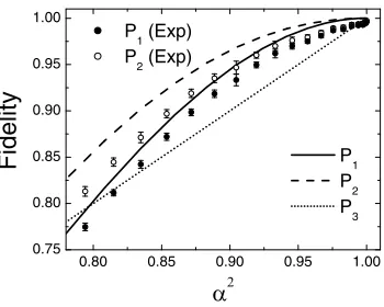
FIG. 1: Comparison of the fidelities of various protocols as a function of the parameterα2
.
the inverse of ˆU; this results in the decoded state ˆΦ(1)L = ˆ
U†|0i h0| ⊗ρˆ(1) L
ˆ
U . The fidelity of the whole quantum coding-decoding operation for P1 is given by
F1=
X
L
1 8hBL|Φˆ
(1)
L |BLi=α8(1 + 2β2)2 . (8)
F1 is plotted as the solid curve in Fig. 1 and has a value of 0.9448 atα2= 0.9.
The second protocol, P2, yields a higher fidelity than that of P1. In this case Alice prepares the quantum chan-nel in the state|00iin the event that her projection mea-surement results in the state|1i. This operation results in the average state of the quantum channel as
ˆ
ρ(2)L =α4(1 + 2β2)|µ
Li hµL|+β4(1 + 2α2)|00i h00| . (9)
Bob again adds an extra qubit in the state|0iand ap-plies the inverse operation ˆU† to produce state ˆΦ(2)
L =
ˆ
U†|0i h0| ⊗ρˆ(2) L
ˆ
U which has a corresponding fidelity of
F2=α8(1 + 2β2)2+α6β4(1 + 2α2). (10)
The value ofF2is plotted as the dashed curve in Fig. 1.
F2 has a value of 0.9652 atα2= 0.9.
Finally, Jozsa and Schumacher also considered the sim-ple protocol, P3, where Alice discards the state of every third letter and encodes the remaining letters in a block of 2 qubits, and Bob generates the state|0ifor the miss-ing letter state. This protocol yields an average fidelity of
F3=α2 , (11)
which is plotted as the dotted curve in Fig. 1.
[image:2.612.354.529.59.199.2]Optical scheme
0 A E D2 A D A B C D B A C D
1 2 3 4
D1 D3 D4 D5 D6 HWP PBS B A 0 A E D2 A D A B C D B A C D
1 2 3 4
[image:3.612.328.554.51.197.2]D1 D3 D4 D5 D6 HWP PBS HWP PBS B A
FIG. 2: Linear optics implementation of three-qubit block coding and decoding.
photodetectors. One photon is used to represent the 3 qubits in terms of two location qubits (the first 2 qubits) and a polarization qubit [4] (the third qubit). The paths labeled A, B, C and D represent the states |00i, |01i,
|10iand|11iof the first two qubits, respectively, and the polarization directions in the plane and perpendicular to the plane of the optical circuit represent the states |0i
and |1i of the last qubit, respectively. We parameter-ize the nth letter state by the angleθn= 12arcsin(βLn). The orientation of the fast axis of each wave plate to the vertical direction is given beside the wave plate in the figure.
First we discuss the preparation of the 3-qubit block state |BLi. A horizontally-polarized photon enters the quantum circuit at position E. The first location qubit is prepared by the λ/2 wave plate and the polarization beam splitter between vertical lines labeled 0 and 1 in terms of angle θ1. Similarly, the second location qubit and the polarization qubit are prepared between the ver-tical lines labeled 1 and 2, and 2 and 3, respectively. (Note that the photodetectors D3, D4, D5 and D6 are not used in state preparation.) The fully state-prepared block appears as a photon in a superposition of 4 path and two linear polarization modes along the vertical line labeled 3. This is the 3-qubit message Alice wants to compress and communicate to Bob.
Next we discuss the quantum coding which takes place between vertical lines 3 and 4. The unitary transforma-tion ˆU is performed by the polarization beam splitter and the twoλ/2 wave plates in this section. The projec-tion measurement of the first qubit is performed by the photodetectors D1 and D2 where the detection or non detection of a photon projects the state onto |1ior |0i, respectively. The circuit in Fig. 2 implements protocol P1 explicitly: if the photodetectors D1 and D2 detect a photon no quanta will be present in the quantum channel and so the coding results in failure. The projective mea-surement is destructive in this case. Protocol P2 can be implemented by switching a horizontally-polarized sin-gle photon source into the optical path A to encode the state |000i each time one of the photodetectors D1 or D2 detects a photon. The encoded (compressed) 2-qubit message appears along vertical line 4. This is transmitted
PZT1 D0 PZT2 lens attenuator He-Ne Laser CR2 CR1 APD1 APD2 APD3 D6 APD6 APD5 APD4 D1 D2 D3
D4, D5
pin hole HWP PBS PZT1 D0 PZT2 lens attenuator He-Ne Laser CR2 CR1 APD1 APD2 APD3 D6 APD6 APD5 APD4 D1 D2 D3
D4, D5
pin hole
HWP PBS
[image:3.612.64.292.51.175.2]HWP PBS
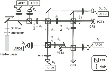
FIG. 3: Experimental setup.
to Bob.
The decoding of the quantum channel AB at Bob’s site requires a mirror image of the quantum circuit in Fig. 2 between lines 3 and 4 but without the photodetectors D1and D2. Moreover, the mirror image of the circuit to the left of the line 3 can be used to determine the fidelity of the decoded block message. The fidelity test results in a ‘yes’-‘no’ answer for each coded-decoded block state as follows. The ‘yes’ answer (i.e. perfectly reconstructed letter block) is indicated by the horizontally-polarized photon emerging from the mirror image of point E. A ‘no’ answer is indicated by the photon being detected by one of the photodetectors D3, D4, D5 or D6 in the mirror image circuit [5].
Experimental Implementation
Our actual experimental circuit is shown in Fig. 3. Again, the orientation angleθn of each λ/2 wave plate is given in the figure. For practical convenience, we did not con-struct an additional mirror-image circuit for the decoding and fidelity check. Instead we use corner reflectors (CR1 and CR2) to reflect the light in the quantum channel back through the circuit (shown as dotted lines in the figure) so that the coding and state-preparation circuits operate as decoding and state-measurement circuits for the reflected light. We use strongly attenuated light from a He-Ne laser (wavelength 632.8 nm) as our single photon source. The CW laser output of 1 mW power is attenu-ated to≈50 fW which corresponds to an average photon flux of 105 photons/sec. The average time between pho-tons through our experiment far exceeds the time taken for light to pass through the circuit (≈10−8s).
1 2
3 4
5 6 0
1x10
5
2x10
5
3x10
5
4x10
5
5x10
[image:4.612.76.294.79.248.2]5
|111> |110> |101> |100> |011> |010> |001> |000>
P
h
o
to
n
C
o
u
n
ts
[
c
o
u
n
t/
s
e
c
]
Cod e P
atte rns
L
Port
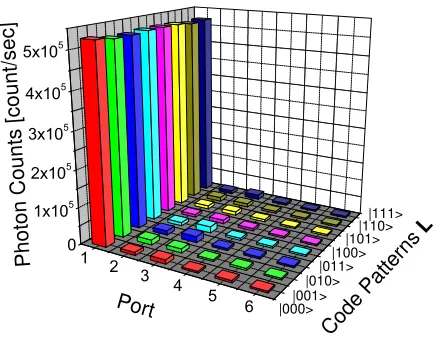
FIG. 4: Histogram of photon counts for each block stateL. The number in the vertical axis labels six APDs from APD1 to APD6. The parameter of the letter states and the fidelity are α2 = 0.9046 and F = 0.933±0.006, respectively. The
gating time of APDs is 5 sec.
In essence, the optical circuit consists of a Michael-son and a Mach-Zehnder interferometers controlled by Piezo transducers PZT1 and PZT2, respectively. We use a bright reference light and adjust the voltages of PZT1 and PZT2 to produce visibilities of more than 98% for these interferometers. The reference light is then switched off and the signal photons are guided into the circuit. The single photon events are counted by six APDs for each block state|BLi. The gating time of the APDs is 5 sec with the combined count over 1 sec being of the order of 105. Since the whole apparatus is shielded by a black box, the number of background photons is much smaller than the dark count of the APDs. Also we estimate the number of events where two photons are present simultaneously in the circuit to be less than half the dark count.
Our use of a photon source with random arrival times means that the quantum coding-decoding operations oc-cur in the context of post-selection measurements; that is, we know that a quantum coding-decoding operation has taken place after it has occurred, and, due to the limited efficiency of the photodetectors, in a subset of possible cases.
The experimental fidelity for protocol P1 is given by
Fex 1 =
X
L
1 8
NL
0
P6
j=0NjL
(12)
whereNL
j is the number of photons detected by the de-tector Djfor the block state|BLi. As an example, Fig. 4
shows the photon counting data for the letter state with
α2= 0.9046 for which the fidelityF = 0.933±0.006. By
varying the angleθ the fidelity of our quantum coding-decoding experiment can be compared by the theoretical predictions given of the previous section over a range of
αvalues. The results are shown in Fig. 1 as solid circles. For protocol P2, rather than switching a horizontally-polarized light source into channel A each time one of the photodetectors D1 or D2 records a photon, we perform a 2 step procedure as follows. The first step is the same as for protocol P1 and, in fact, we use the same photon counting data NL
j as described. The second step cor-responds to the transmission of a horizontally-polarized photon in channel A for each of the photons detected by D1and D2in the first step. For this purpose, the corner reflector CR1 is removed and horizontally-polarized and attenuated light from a He-Ne laser is directed into the circuit. The number of photons used (i.e. the total num-ber of photons detected by all APDs) in this second step is adjusted to beNL
1 +N2Lfor each corresponding block state|BLi. We can do this adjustment with an accuracy
of ±3% by carefully controlling the gating time of the APDs. The total fidelity for this protocol is calculated as follows:
F2ex=
X
L
1 8
NL
0 +NL (2) 0
P6
j=0NjL
. (13)
where N0L(2) is the total number of photons detected by D0 in the second step. We obtain the fidelities corresponding to severalαvalues and plot them as open circles in Fig. 1. The experimental fidelities for both protocols exceed that of the simple protocol.
Discussion
A message of equal-likely letters is not compressible clas-sically. In contrast, quantum source coding allows a quantum message of equally likely (but non orthogonal) letter states to be compressed [1, 2]. Our compression of 3-qubit codewords gives a clear demonstration of this fundamental principle.
The practical application of quantum source coding faces several challenges. An immediate task is to demon-strate quantum source coding using a single-photon-on-demand source. Another is to replace spatial mode qubits with frequency mode qubits as this leads to compression of bandwidth of quantum carrier. Of direct practical im-portance is to demonstrate the coding and decoding of a source of weak coherent states. Quantum circuits based on measurement induced non-linearities and non-classical light sources have potential in this regard. Our experi-ment is the first step towards realizing these practical goals.
Acknowledgments
Marie Curie Fellowship program.
[1] B. Schumacher, Phys. Rev. A51, 2738 (1995).
[2] R. Jozsa and B. Schumacher, J. Mod. Opts. 41, 2343 (1994).
[3] We perform the unitary transformation before the projec-tion operaprojec-tion, otherwise our scheme is identical to that of [2].
[4] N. J. Cerf, C. Adami, and P. G. Kwiat, Phys. Rev. A57, R1477 (1998); R. J. C. Spreeuw, Found. Phys. 28, 361
(1998); S. Takeuchi, Proc. p.299, PhysComp96 (Boston, 1996).