Int. J. Electrochem. Sci., 13 (2018) 12155 – 12162, doi: 10.20964/2018.12.09
International Journal of
ELECTROCHEMICAL
SCIENCE
www.electrochemsci.orgCore-shell MnO
2/S Composite as High-Performance Cathode
Materials for Li-S Batteries
Yinxia Chen, Xianbing Ji*
Hebei University of Environmental Engineering, Qinhuangdao, Hebei, 066102, China *
E-mail: [email protected]
Received: 25 July 2018 / Accepted: 6 September 2018 / Published: 5 November 2018
A novel structure of core-shell MnO2/S composite was designed as cathode materials for Li-S batteries. This structure could efficiently inhibit the polysulfide dissolution and improve the conductivity at the same time. As a result, the cycle performance of Li-S battery was greatly improved due to the presence of core-shell MnO2/S composite. The results show that the specific capacity of core-shell MnO2/S composite is 1200 mAh g-1 at 0.1 C. After 100 cycles, the specific capacity remains 715 mAh g-1 at 0.5 C, showing perfect cycle performance.
Keywords: Core-shell structure, MnO2/S composites, Li-S battery, Electrochemical performance
1. INTRODUCTION
Energy storage is a hot topic for the researchers all over the world with the large energy consumption [1, 2, 3]. To satisfy the demand of energy need, many kinds of energy storage systems have been developed, such as Li-ion battery, Li-S battery and Li-Air battery [4-8]. Among these systems, lithium-sulfur battery is the most promising candidate due to its high specific capacity (1267 mAh g-1) and high energy density (2600 Wh kg-1) [9-12]. Therefore, much attention has been paid on the research of Li-S battery by the researchers. However, many problems still exist during the process for the commercialization of Li-S battery [13, 14]. The most severe issues are the poor conductivity and polysulfide dissolution during the electrochemical process [15, 16, 17]. As a result, to achieve the excellent performance of Li-S battery, the main challenge is enhance the conductivity and restrain the dissolution of polysulfide [18, 19].
applied in Li-S battery, such as carbon nanofiber [22], carbon sphere [23] and carbon nanotube [24]. With the development of cathode materials, Cui developed yolk-shell TiO2/S composite as cathode material for Li-S battery [25]. Lou had prepared MnO2 nanosheets hollow carbon composite host material for sulfur. The as-prepared MnO2@HCF/S composite exhibited long cycle stability [26]. After that, the metal oxides become the new host materials for sulfur.
In this paper, a novel structure of core-shell MnO2/S composite was designed as cathode materials for Li-S battery. This structure could efficiently inhibit the polysulfide dissolution and improve the conductivity at the same time. As a result, the cycle performance of Li-S battery was greatly improved due to the employment of core-shell MnO2/S composite.
2. EXPERIMENTAL
2.1. Preparation of MnO2/S composite
Firstly, the sulfur was prepared via solution method. Typically, 0.8 ml HCl and 60 ml Na2S2O3 were mixed together. After 2 h for adequate reaction, 10 ml PVP solution was added and the solution was named sulfur solution. For MnO2 coating, the sulfur solution was mixed with 15 ml MnSO4 aqueous solution and 30 ml KMnO4 aqueous solution. After reaction for 5 h, the solution of MnO2/S core-shell particles were washed by water for 5 times. Finally, the as-prepared core-shell MnO2/S composites were dried in vacuum for 24 h.
2.2. Materials characterization
The morphology of core-shell MnO2/S composite was obtained from Transmission electron microscopy (TEM, Ultra55). X-ray diffraction (XRD) measurements were carried out on a D8 Advance (Bruker, Ltd). Thermal gravimetric analysis (TGA, TA SDT-Q600) was conducted under nitrogen flow with a heating rate of 5℃ min-1.
2.3. Electrochemical measurements
The electrochemical performances of sulfur and core-shell MnO2/S composite electrodes were evaluated by using CR2016 coin batteries. The galvanostatic charged/discharged tests were performed in the voltage range of 1.5-3.0 V on LAND battery tester. Electrochemical impedance spectra (EIS) measurement was carried out on an electrochemistry workstation (CHI660E).
3. RESULTS AND DISCUSSION
dissolution. As shown in Figure 1, comparing with sulfur cathode, the as-prepared core-shell MO/S composites could trap the polysulfide effectively, while the pure sulfur cathode suffers from shuttle effect due to the polysulfide dissolution.
Figure 1. Schematic of discharge process for (a) sulfur and (b) core-shell structure MO/S composites.
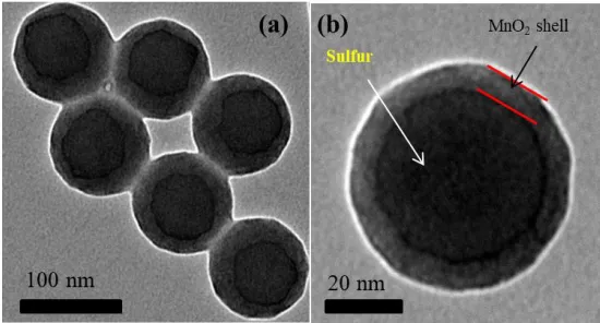
Figure 2 (a) and (b) display the TEM images of the core-shell MO/S composite at different magnification. Figure 2 (a) and (b) show the same morphology of core-shell MO/S composite. From the figure, it can be seen that the MO/S composites show a spherical structure with uniform size and shape, and its edge part is bright and the middle part is dark. This is because the sulfur particles are surrounded by MnO2 layers.
Figure 2. The TEM images of yolk-shell MO/S composites at different magnification.
[image:3.596.119.477.139.259.2] [image:3.596.159.434.429.577.2]
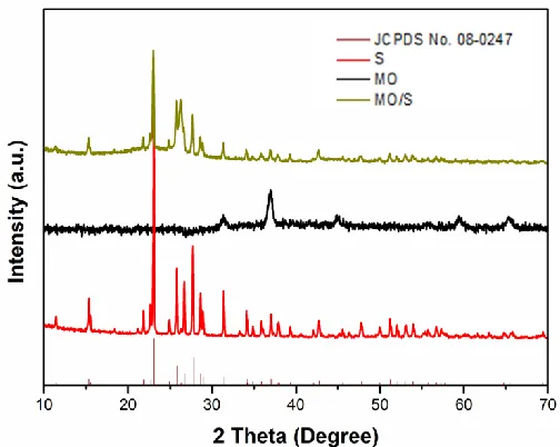
Figure 3. The XRD patterns of sulfur, MnO2 and MO/S composites at 2 theta from 10° to 80°.
Figure 4 shows the TG curve of the core-shell MO/S composites under N2 atmosphere. As shown in Figure 4, the temperature range of the mass loss of the core-shell MO/S composite is mainly located at 200~300℃. By calculation, the content of sulfur in the core-shell MO/S composite is about 74.35%.
Figure 4. The TG curve of MO/S composites from room temperature to 700℃.
[image:4.596.173.425.71.272.2] [image:4.596.182.413.424.594.2]
Figure 5. The first DC curves of pure sulfur electrode and MO/S composite electrode at the current density of 0.1 C.
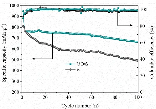
The cycle performance of pure sulfur electrode and MO/S composite electrode was tested at the current density of 0.5 C for 100 cycles. As shown in figure 6, it can be seen that the capacity of pure sulfur electrode is only 492 mAh g-1 after 100 cycles at the current density of 0.5 C. For the MO/S composite electrode, the capacity still remain at 712 mAh g-1 after 100 cycles with a capacity retention of 85%. Besides, the columbic efficiency for MO/S composite electrode is as high as 98%, which is higher than the 92% of sulfur electrode [28].
Figure 6. The cycling performances of pure sulfur electrode and MO/S composites electrode at the current density of 0.5 C.
[image:5.596.172.425.71.248.2] [image:5.596.174.423.449.623.2]
1 C, the specific capacity still is 795 mAh g-1. Moreover, when the current density comes back 0.1 C, the capacity could recover its pristine capacity value. However, the pure sulfur electrode fails to endure various current densities, suffering from severe capacity fade [29]. This result proves to be that the MO/S composite electrode has excellent rate performance.
Figure 7. The rate performances of pure sulfur electrode and MO/S composite electrode at various current densities.
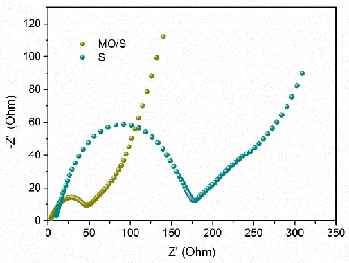
Figure 8 shows electrochemical impedance spectrum of the core-shell MO/S composite and pure sulfur cathode before the cycle performance test. From figure 8, it can be seen that the test curves are made up of the semicircle in the high frequency zone and slant line in the low frequency region [30]. The semicircle in the high frequency region is related to the charge transfer resistance (Rct); the slant in the low frequency region represents the Warburg impedance (W), which indicates the solid diffusion of Li+ in the electrode materials [31]. The charge transfer resistance of the core-shell MO/S composite electrode is obviously lower than that of the pure sulfur electrode. Besides, the presence of MO has a certain adsorption on the polysulfide.
[image:6.596.178.417.158.337.2] [image:6.596.173.425.550.740.2][image:7.596.98.496.187.259.2]
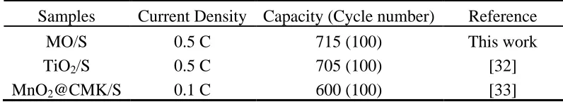
Furthermore, to demonstrate the excellent electrochemical performance of the MO/S composite cathode material, the comparison of electrochemical performance for similar cathode materials is listed in Table 1. It can be seen that the MO/S composites exhibit stable cycle performance among these reported cathode materials for lithium-sulfur batteries.
Table 1 The comparison of various cathode materials for Li-S batteries.
Samples Current Density Capacity (Cycle number) Reference
MO/S 0.5 C 715 (100) This work
TiO2/S 0.5 C 705 (100) [32]
MnO2@CMK/S 0.1 C 600 (100) [33]
4. CONCLUSIONS
In conclusion, core-shell MO/S composites were successfully prepared via solution method. The as-prepared MO/S composites show core-shell structure, which is advantageous to the inhibition of polysulfide. As a result, the Li-S battery with core-shell MO/S composites exhibits superior electrochemical performance. Its specific capacity is 1200 mAh g-1 at the current density of 0.1 C. After 100 cycles, the specific capacity remains 715 mAh g-1 at the current density of 0.5 C. Moreover, the MO/S composites display a high specific capacity of 706 mAh g-1 at high current density of 1 C, indicating excellent rate performance. In all, the core-shell MO/S composites could be promising cathode materials for the commercialization of Li-S batteries.
ACKNOWLEDGEMENT
This work was funded by Qinhuangdao Key Laboratory of Environment Funcational Materials, the scientific research Project item of Hebei province education office (QN2016032), and the Prominent Talent Project, Hebei University of Environmental Engineering (BJRC201701).
References
1. R. Xu, Y. Z. Sun, Y. F. Wang, J. Q. Huang and Q. Zhang, Chinese Chem. Lett., 28 (2017) 2235. 2. X. Zhang, H. Xie, C. S. Kim, K. Zaghib, A. Mauger and C. M. Julien, Mater. Sci. Eng. R., 121
(2017) 1.
3. Z. Li, N. Zhang, Y. B. Sun, H. Z. Ke and H. S. Cheng, J. Energy Chem., 26 (2017) 1267. 4. Z. Li, B. Y. Guan, J. T. Zhang and X. W. Lou, Joule, 1 (2017) 576.
5. J. Q. Guo, J. Li, Y. J. Huang, M. Zeng and R. F. Peng, Mater. Lett., 181 (2016) 289. 6. H. Zhang, P. K. Zuo, J. F. Hua, Y. L. Ma, C. Y. Du, X. Q. Chen, Y. Z. Gao and G. P. Ying,
Electrochim. Acta, 238 (2017) 257.
7. R. P. Fang, G. X. Li, S. Y. Zhao, L. C. Yin, K. Du, P. X. Hou, S. G. Wang, H. M. Cheng, C. Liu and F. Li, Nano Energ., 42 (2017) 205.
8. J. Li, J. Q. Guo, L. Zeng, Y. J. Huang and R. F. Peng, Rsc Adv., 6 (2016) 26630.
175.
11.Y. L. Deng, J. Y. Li, T. H. Li, X. F. Gao and C. Yuan, J. Power Sources, 343 (2017) 284.
12.H. W. Wu, Y. Huang, W. C. Zhang, X. Sun, Y. W. Yang, L. Wang and M. Zong, J. Alloy Compud., 708 (2017) 743.
13.X. J. Liu, N. Xu, T. Qian, J. Liu, X. W. Shen and C. L. Yan, Nano Energ., 41 (2017) 758.
14.Z. Li, S. F. Deng, H. J. Li, H. Z. Ke, D. L. Zeng, Y. F. Zhang, Y. B. Sun and H. S. Cheng, J. Power Sources, 347 (2017) 238.
15.S. B. Zeng, L. G. Li, L. H. Xie, D. K. Zhao, N. Zhou, N. Wang and S. W. Chen, Carbon, 122 (2017) 106.
16.X. Song, T. Gao, S. Q. Wang, Y. Bao, G. P. Chen, L. X. Ding and H. H. Wang, J. Power Sources, 356 (2017) 172.
17.Y. S. Ye, L. L. Wang, L. L. Guan, F. Wu, J. Qian, T. Zhao, X. X. Zhang, Y. Xing, J. Q. Shi, L. Li and R. J. Chen, Energ. Storage Mater., 9 (2017) 126.
18.N. P. Deng, Y. Wang, J. Yan, J. G. Ju, Z. J. Li, L. L. Fan, H. J. Zhao, W. M. Kang and B. W. Chen, J. Power Sources, 362 (2017) 243.
19.S. Q. Li, G. F. Ren, Z. H. Dong and Z. Y. Fan, Appl. Surf. Sci., 396 (2017) 637.
20.H. L. Wu, Y. L. Deng, J. R. Mou, Q. J. Zheng, F. Y. Xie, E. Y. Long, C. G. Xu and D. M. Lin, Electrochim. Acta, 242 (2017) 146.
21.Ji, X., K.T. Lee, and L.F. Nazar, Nat. Mater., 8 (2009) 500.
22.H. Gao, Q. Lu, Y. J. Yao, X. H. Wang and F. S. Wang, Electrochim. Acta, 232 (2017) 414. 23.J. Liu, C. W. Wang, B. Liu, X. Ke, L. Y. Liu, Z. C. Shi, H. Y. Zhang and Z. P. Guo, Mater. Lett.,
195 (2017) 236.
24.D. Yang, W. Ni, J. L. Cheng, Z. P. Wang, T. Wang, Q. Guan, Y. Zhang, H. Wu, X. D. Li and B. Wang, Appl. Surf. Sci., 413 (2017) 209.
25.Z.W. Seh, W.Y. Li, J.J. Cha1, G.Y. Zheng, Y. Yang, M.T. McDowell, P.C. Hsu and Y. Cui, Nat. Commun., 4 (2013) 1331-1337.
26.Z. Li, J. T. Zhang, X. W. Lou, Angew. Chem. Int. Edit., 54 (2015) 12886.
27.X. Y. Li, N. Q. Fu, J. Z. Zou, X. R. Zeng, Y. M. Chen, L. M. Zhou and H. T. Huang, Mater. Lett., 209 (2017) 505.
28.M. H. Chen, M. L. Qi, J. H. Yin and Q. G. Chen, Mater. Res. Bull., 96 (2017) 335.
29.X. Q. Yuan, L. S. Wu, X. L. He, L. Huang, X. L. Zhu, H. J. Hou, B. C. Liu, J. P. Hu and J. K. Yang, Chem. Eng. J., 320 (2017) 178.
30.L. Shi, Y. G. Liu, W. K. Wang, A. B. Wang, Z. Q. Jin, F. Wu and Y. S. Yang, J. Alloy Compud., 723 (2017) 974.
31.S. Q. Li, S. Wang, G. F. Ren, and Z. Y. Fan, Carbon, 124 (2017) 212. 32. J. Li, J. Q. Guo, J. N. Deng, Y. J. Huang, Mater. Lett., 189 (2017) 188.
33. J. Liu, C. W. Wang, B. Liu, X. Ke, L. Y. Liu, Z. C. Shi, H. Y. Zhang and Z. P. Guo, Mater. Lett., 195 (2017) 236.