Int. J. Electrochem. Sci., 13 (2018) 11839 – 11852, doi: 10.20964/2018.12.57
International Journal of
ELECTROCHEMICAL
SCIENCE
www.electrochemsci.org
Study on Corrosion of Iron-Zinc Oxide Particulate Composites
Produced by a Spark Plasma Sintering in Hanks' Solution
Miriam Kupková1,*, Martin Kupka2, Monika Hrubovčáková1, Renáta Oriňaková3, Andrea Morovská Turoňová3
, Viktor Puchý1 1
Institute of Materials Research, Slovak Academy of Sciences, Watsonova 47, SK-040 01 Košice, Slovak Republic
2
Institute of Experimental Physics, Slovak Academy of Sciences, Watsonova 47, SK-040 01 Košice, Slovak Republic
3
Department of Physical Chemistry, Institute of Chemistry, Faculty of Science, P.J. Šafárik University, Moyzesova 11, SK-041 54 Košice, Slovak Republic
*
E-mail: [email protected]
Received: 19 August 2018 / Accepted: 1 October 2018 / Published: 5 November 2018
In an attempt to find an based biomaterial which corrodes more rapidly than a pure iron, an iron-zinc oxide particulate composite was produced by spark plasma sintering a mixture of carbonyl iron micropowder and zinc oxide nanopowder. Composite materials with a ZnO content of 0.5, 1.0 and 5.0 wt.% were manufactured in this way and subsequently tested for corrosion in Hanks' solution. The composites were expected to undergo a galvanic corrosion, with Fe acting as the anode and semiconducting ZnO acting as the cathode. Due to a galvanic stimulation, a composite with the lowest content of ZnO actually corroded twice as fast as did a pure iron produced by a spark plasma sintering. However, in the case of galvanic corrosion and for compositions under investigation, the corrosion potential and corrosion rate of a composite could increase with increasing cathode-to-anode area ratio, that is, with increasing content of ZnO. As the content of ZnO was increased, the corrosion potential indeed increased, but the corrosion current per unit area of composite surface decreased. This decrease in corrosion rate was regarded as being a consequence of a poor electric conductance of ZnO regions, which has led to relevant ohmic potential drops (IR drops) along the galvanic current paths through these regions. Some of possibilities to minimize IR drops and thus to maximize the corrosion rate are mentioned.
1. INTRODUCTION
For some clinical applications, the replacement of bioinert implants by bioabsorbable or biodegradable ones is under consideration. Such a transition to implants possessing new performance qualities will be made possible either by the innovative use of current materials or by the development of new materials. Prospective materials for use in biodegradable implants have to satisfy complex engineering as well as medical requirements. For instance, the course of implant's degradation should be adjusted to match the physiological needs of the healing part of the body [1].
The iron and materials based on iron belong to promising candidates. However, the pure iron corrodes too slowly in the hostile body environment. Various approaches have been proposed with the purpose of modifying the degradation rate in order to match the application needs. They basically involve alloying, surface modification, new fabrication methods (see, e.g. [1,2] and references therein). A galvanic stimulation is one of the effective ways of modifying the corrosion rate. Hence, the idea is to manufacture metal-matrix composites consisting of an iron matrix and a dispersed second phase intended to act as the cathode in a galvanic couple with the iron [3].
When a single piece of iron is immersed in an aqueous electrolyte, electrochemical reactions will occur at the interface between the metal and an electrolyte. Due to these reactions, the iron acquires electric potential, called the corrosion potential. The value of corrosion potential is determined by the dynamic equilibrium between opposing electrochemical reactions - oxidation and reduction. Under usual conditions, the oxidation reaction is the metal dissolution, when iron atoms pass from the piece of iron into aqueous electrolyte as iron cations. The predominant reduction reaction is usually one of the hydrogen evolution or oxygen reduction reactions. When the metal is fairly homogeneous and the electrolyte composition does not vary significantly along the metal surface, oxidation and reduction reactions are usually assumed to take place at the same surface sites, that is, there are no preferential cathodic and anodic sites [4].
When two solid pieces, one of iron and the other of some less reactive material, are immersed in the same aqueous electrolyte and are touching each other, electrochemical reactions taking place at the interfaces and the electric contact between materials will force each of materials to a common electric potential somewhere between the potentials that each material would acquire separately in the same electrolyte [5]. The potential of iron is thus shifted toward more positive values. This anodic polarization of iron slows down the reduction reactions and speeds up the oxidation reactions occurring at the iron surface. Iron surface thus becomes a preferential site for oxidation reaction and so the iron corrodes faster than if it was isolated in the same electrolyte. The iron becomes the anode. The less reactive material becomes the cathode, its surface serves as an inert electrode for hydrogen ion or oxygen reduction.
In the literature, the investigation of iron-matrix composites with a tungsten or carbon nanotubes as the second dispersed phase has been reported on [3]. In the present study, zinc oxide was chosen as an additive to the iron matrix. This choice was partly inspired by the use of ZnO (nano)particles as an active antibacterial additive in the antibacterial polymer-matrix composite biomaterials [9]. In that rapidly growing field, ZnO is considered a promising additive - it shows a strong antibacterial activity in pH neutral environments, and represents a source of zinc, a necessary element for the human body. Another reason for such a choice was that ZnO has already shown a catalytic activity in various situations (e.g. [10]).
As to ability to conduct electricity, zinc oxide is a semiconductor. However, though ZnO is even a wide-bandgap semiconductor, it is naturally doped as n-type due to the presence of native donor defects-zinc interstitials and oxygen vacancies [11]. So, a galvanic corrosion of Fe-ZnO metal-matrix composite is in principle possible.
One of the most important factors which affect the behaviour of electrode made up of two different materials is the size of the area of cathodic material relative to that of anodic material at the electrode's surface exposed to the electrolyte. A simple model based on quite common premises says that the overall measured potential of such an electrode should increase with increasing cathode-to-anode area ratio, and that the corrosion current per unit area of electrode's surface should increase, reach a maximum, and then decrease when the cathode-to-anode area ratio is increased. The maximum corrosion current usually occurs when the area of cathode equals that of anode [12].
In accordance with expectations, corrosion potentials of investigated Fe-ZnO metal-matrix composite samples increased with increasing weight fraction and hence area fraction of ZnO particulates. But the corrosion current density decreased with increasing weight fraction of ZnO, though the area ratios of cathode to anode were well below unity. This decreasing trend could be due to increasing ohmic potential drops through ZnO regions, the resistance of which is evidently not negligible and is increasing with ZnO content.
The passage of an electric current through a medium of finite resistivity results in a potential drop that will occur along the current path according to the Ohm's law [13]. The ohmic potential drops due to the flow of a galvanic current through the components of the system considered can affect the distribution of electric potential throughout the specimen's surface and thus also the course of galvanic corrosion.
When the materials of which the electrode is made are good electric conductors and the electrolyte adjacent to the electrode possesses low resistivity, these ohmic potential drops are negligible relative to the values of relevant redox and corrosion potentials and can be ignored.
The situation is different if some of materials conduct an electric current very poorly. The arisen ohmic potential drop (IR drop) prevents the cathodic and anodic materials from reaching exactly the same potential, that is, cathode and anode are at different potentials [5]. This is associated with the slowing down of the corrosion of anodic material in comparison with the situation if there were no potential drops. The higher the IR drop, the larger the reduction in the rate of galvanic corrosion [13].
pass [13]. As the ohmic potential drop is increased, the corrosion rate decreases. So, the decrease in corrosion current density with increasing content of ZnO can be observed.
2. EXPERIMENTAL 2.1. Materials
The carbonyl iron powder fy BASF, type CC, d50 value 3.8–5.3 μm, and the zinc oxide nanopowder fy Alfa Aesar, 40-100nm APS were used as a starting material. Pure carbonyl iron powder was a raw material for reference samples. To obtain a raw material for composite samples, three powder mixtures were prepared by blending individual powders. These mixtures consisted of 99.5 wt.%Fe and 0.5 wt.%ZnO, 99 wt% Fe and 1 wt% ZnO, and 95 wt.% Fe and 5 wt.% ZnO, respectively. To make powder mixtures homogeneous, the resonant acoustic homogenization technique utilizing the LabRAM mixer was used.
The 18 gram doses of a powder were weighed out and then consolidated by a spark plasma sintering in the FAST/SPS sintering equipment, model HP D10-SD (FCT - Systeme GmbH, Germany). A cylindrical graphite die with the inner diameter of 30 mm was used, and a 0.5 mm thick graphite sheet was inserted at the interface between die and powders to stabilize electric contacts and to reduce reactions of powders with the material of die. Punches, die and a powder content of die were heated up at a rate of 100oC/min in a vacuum, and then, to ensure the conversion of a powder into a coherent body, the substance in a die was held at the temperature of 950oC under the uniaxial pressure of 35MPa for 15 minutes.
After the sintering process was completed, all manufactured discs were ground and polished to remove surface layers contaminated with a carbon. Prismatic specimens were then cut from prepared iron and composite discs using a low-speed saw and a diamond blade.
2.2. Methods
2.1 Metallographic examination
To prepare samples for metallographic examinations, they were mounted, ground, polished with 0.1 mm diamond paste and etched with 2% nital solution. The microstructure of specimens was investigated using a light microscope (Olympus GX71, Japan) and a scanning electron microscope coupled with an energy dispersive spectrometer (JEOL JSM-7000F, Japan with EDX INCA).
2.2 Volume and area fraction evaluation
After the mass m and volume V of the sample were measured, the volume fraction v of an individual constituent was calculated according to the formula
. (1)
Here wi is the weight fraction and ρi is the mass density of the constituent i.
For a composite with more or less randomly distributed second phase, the volume fraction of the constituent is numerically equal to the area fraction of the composite's surface occupied by this constituent [14], that is
. (2)
The porosity of the sample, that is, the volume fraction of void vvoid, was simply calculated
from the relation
. (3)
2.3 Immersion experiment
Samples selected for the long-term immersion corrosion test were ultrasonically cleaned in acetone and ethanol for 10 minutes each. Samples were then immersed in 50 ml of Hanks' solution simulating the extracellular body fluids.
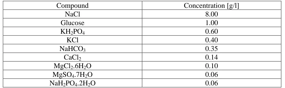
[image:5.596.63.535.547.693.2]For each experiment, Hanks' solution was freshly prepared using laboratory grade chemicals and double distilled water. Composition of Hanks' solution is presented in Tab.1. The solution's pH value was 7.4.
Table 1. Hanks' solution constituents and their concentrations
Compound Concentration [g/l]
NaCl 8.00
Glucose 1.00
KH2PO4 0.60
KCl 0.40
NaHCO3 0.35
CaCl2 0.14
MgCl2.6H2O 0.10
MgSO4.7H2O 0.06
NaH2PO4.2H2O 0.06
Samples have been weighed before and after exposure. If the mass determined by measuring the sample after exposure can be accepted as an accurate assessment of the mass of remaining unaffected material, the average corrosion rate can be calculated according to the formula [15]
(4) Here mi is the initial mass of the sample (before exposure), mf is the final mass of the sample
(after exposure), A is the exposed surface area and T is exposure time. 2.4 Polarization experiment
To determine an instantaneous rate at which the specimen corrodes in Hanks' solution, the potentiodynamic polarization technique was used.
Electrochemical measurements were carried out using an Autolab PGSTAT 302N potentiostat, interfaced to a computer. A typical polarization cell arrangement was utilized, with the Ag/AgCl/KCl (3 mol/l) reference electrode, a platinum counter electrode and Fe or Fe-ZnO composite sample as the working electrode. Hanks' solution was used as an electrolyte. Its preparation and properties were described above. A constant electrolyte temperature of 37±2°C was maintained using a heating mantle. All potentiodynamic polarization studies were performed after one hour stabilization of the free corrosion potential. During the tests, the potential of working electrode has been varied from -800 mV to -200 mV (vs. Ag/AgCl/KCl (3 mol/l)) at a scanning rate of 0.1 mV/s, and polarization curves were recorded. Tafel plots were constructed. The corrosion current density icorr was determined using the
Tafel extrapolation method.
If the anodic current is almost exclusively due to Fe2+ ions, the instantaneous dissolution rate of iron can be calculated according to the formula [15]
(5)
where icorr is corrosion current density. M is the molar mass of dissolved element (in this case
iron), n is a number of electrons released in the dissolution reaction (in this case two), and F is Farraday's constant.
Actually, the relation (5) represents the instantaneous rate of Fen+ ions leaving from the sample surface. Assuming that the weight fraction of iron in the released material is nearly the same as in the parent specimen, the instantaneous corrosion rate of the specimen, understood as the specimen's mass loss per unit area per unit time, can be then calculated according to the formula [15]
(6)
Here wFe represents the iron weight fraction in corroding specimen.
2.5 Modul elasticity
The modulus of elasticity was determined by the dynamic resonant method. The natural frequency of the fundamental bending mode was measured by means of an equipment BUZZOSONIC 5.9.6, USA, and the corresponding bending stiffness was evaluated for each of prismatic specimens. The modulus of elasticity was then calculated as the ratio of bending stiffness to the appropriate area moment of inertia of the prism cross section. If the specimen is macroscopically homogeneous, this ratio represents the true Young’s modulus of a material the specimen is made of [16]. If the specimen is macroscopically heterogeneous, the bending stiffness is connected with material properties and geometric characteristics in a more complex way [17], and the above ratio is treated as an effective modulus of elasticity reflecting the elastic response of the sample as a whole.
3. RESULTS AND DISCUSSION
To consolidate powders, the spark plasma sintering method utilizes uniaxial pressure along with a pulsed electric current in one step. The graphite punches, die and, if conductive, also powder are heated up by Joule heating from a current flowing through them. The appearance of a high-temperature plasma generated by spark discharges in voids between particles during DC pulsing is often mentioned, but this is still a controversial and not commonly accepted issue [18]. Simultaneous action of Joule heating and mechanical pressure leads to the formation of large contact areas between particles and thus to a higher density.
In the case considered here, the displacement of iron during deformation of particles and formation of interparticle bonds has pushed ZnO nanoparticles along the moving surface of iron particles.
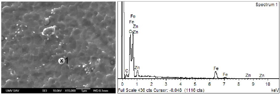
[image:7.596.71.526.505.658.2]
Figure 2. A SEM image of the Fe-matrix ZnO-particulate composite with the ZnO content of 1.0wt.%.
This has led to an increase in ZnO concentration in certain regions. Since the magnitude of current flowing through a given path is inversely proportional to the path's resistance, it was expected that a large amount of the applied current flowed through iron powder mass around ZnO particulates, and only the very small amount of current flowed through ZnO regions. The ZnO regions were therefore heated up predominantly, but not exclusively, indirectly by a heat transport from surroundings. This most likely resulted in the formation of weakly bound agglomerates rather than strongly bound aggregates of ZnO nanoparticles.
Figures 1 through 4 show Fe-ZnO metal-matrix composites prepared by a spark plasma sintering. The presented images were captured using both light microscope (LM) and scanning electron microscope (SEM).
[image:8.596.110.493.488.632.2]
Figure 4. LM images of the Fe-matrix ZnO-particulate composite with the ZnO content of 5.0wt.%. Figure shows composite's section perpendicular (a) and parallel (b) to the direction of pressure during spark plasma sintering. Section (b) was etched with nital.
Fig. 1 illustrates that ZnO particulates survived the procedure of spark plasma sintering. An example of formation of large contact areas between original Fe particles is presented in Fig. 2. The ZnO-lined contacts between original iron particles are visible.
Figs. 3 and 4 show microstructures of some of investigated composites, with quite non-equiaxed agglomerates of ZnO nanoparticles.
It was already demonstrated [3] that a pure iron prepared by a spark plasma sintering corroded faster than a pure cast iron in Hanks' solution. This was attributed to a galvanic interaction between iron grain faces and grain boundaries. Grain boundary zones were active (anodic sites) and grain faces were passive (cathodic sites) [4].
It was expected that in a material prepared by spark plasma sintering and having ZnO nanoparticles along iron grain boundaries, the galvanic interaction between ZnO and iron will take on the leading role. But now with the iron grain faces acting as the anode and ZnO-lined grain boundaries acting as the cathode.
In the case of an ordinary dissimilar metal corrosion, the corrosion potential increases as the cathode - to - anode area ratio is increased. The corrosion current per unit area of sample surface shows a maximum at a cathode - to - anode area ratio of unity, diminishes both at ratios greater or lesser than unity, and tends to zero if the cathode-to-anode area ratio approaches to either zero or infinity [12].
In the case of corrosion of Fe-ZnO metal-matrix composites investigated here, the corrosion potential increased as the ZnO content was increased, that is, as the cathode-to-anode area ratio was increased, in accordance with expectations.
[image:9.596.108.492.70.213.2]
Table 2. Corrosion characteristics of typical specimens from Fe-matrix ZnO-particulate composites in Hanks' solution. For information purposes, a pure cast iron corrodes at a rate of 0.016 mg/cm2.day in Hanks' solution [3].
specimen corrosion potential
[mV]
corrosion current density
[µA.cm-2]
Tafel slope [mV/dec]
iron dissolution rate [mg/cm2.day]
specimen corrosion rate [mg/cm2.day] anodic cathodic
Fe -510.8 14.14 55 250 0.354 0.354
Fe+0.5ZnO -515.4 32.19 70 95 0.805 0.809
Fe+1.0ZnO -507.5 10.01 60 107 0.250 0.253
Fe+5.0ZnO -501.9 7.75 60 85 0.194 0.204
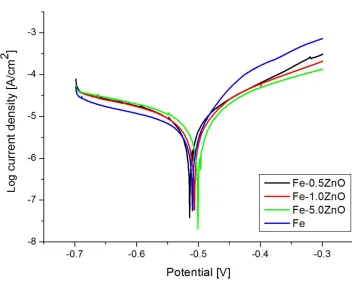
Tab. 2 lists corrosion characteristics of typical specimens, as determined by polarization experiments. Table 3 shows volume fractions of constituents relevant for these specimens. Typical Tafel plots are depicted in Fig. 5.
Note that the corrosion rate of a composite with ZnO content of 0.5wt.% was higher than that of a pure iron prepared by a spark plasma sintering, that is, the ZnO is in principle able to accelerate the corrosion of Fe-based materials.
Table 3. Volume fractions of relevant constituents in typical specimens from Fe-matrix ZnO-particulate composites. The zinc oxide- to-iron volume ratio is numerically equal to the cathode-to- anode area ratio when the composites are exposed to Hanks' solution.
Specimen mass density [g.cm-3]
iron volume fraction [%] zinc oxide volume fraction [%] void volume fraction [%]
zinc oxide to iron volume
ratio
Fe 7.51 95.42 0 4.58
Fe+0.5ZnO 7.72 97.65 0.69 1.66 0.0071
Fe+1.0ZnO 7.47 93.94 1.33 4.73 0.0142
Fe+5.0ZnO 7.36 88.86 6.56 4.58 0.0738
[image:10.596.51.546.525.695.2]
ignored. The potential drop shifts the potential of an iron matrix to more cathodic values and thus slows down iron corrosion in comparison with a situation if there was no IR drop. Metal-matrix composites with higher ohmic potential drops within the material tend to have lower corrosion rates [13].
Figure 5. Tafel plots for typical specimens from Fe-matrix ZnO-particulate composites in Hanks' solution.
In the case of composites under investigation, when ZnO was used in a form of nanoparticles and spark plasma sintering was performed at a quite low temperature, the increase in ZnO content has led to the increase in size of ZnO regions formed by agglomerates of weakly bound ZnO nanoparticles, that is, by agglomerates with a lot of highly resistive interparticle contacts. With increasing size of ZnO regions, their resistance became higher and the ohmic potential drop through such regions became more significant. So, the corrosion rate could decrease with increasing ZnO content.
The effect of reinforcement resistivity on the corrosion behaviour of composites was demonstrated, e.g., for SiC/Al MMCs [19]. For the samples with the same volume fraction of SiC, but in one case it was a green SiC with a high purity and hence with a high resistivity, in the other case it was a black SiC with a low resistivity, the corrosion rates were lower for samples reinforced with a green SiC than for those reinforced with a black SiC [19].
[image:11.596.110.462.178.459.2]
Table 4. Mass and dimensions of typical specimens from Fe-matrix ZnO-particulate composites before (initial values) and after (final values) their eight-week immersion in Hanks' solution.
specimen mass [mg] height [mm] width [mm] lenght [mm]
initial Final initial final initial Final initial Final
Fe 1447.5 1447.0 1.76 1.77 5.00 5.00 21.89 21.94
Fe+0.5ZnO 1634.0 1633.0 1.94 1.95 4.96 4.97 22.04 22.07 Fe+1.0ZnO 1587.9 1585.4 1.94 1.94 4.99 5.00 21.98 21.98 Fe+5.0ZnO 1373.9 1373.6 1.71 1.72 5.00 5.01 21.87 21.86
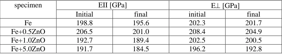
Table 5. The effective elastic moduli of typical specimens from Fe-matrix ZnO-particulate composites. The presented values were determined from natural frequencies of flexural vibrations parallel and perpendicular to the directions of pressure during spark plasma sintering. Initial (final) values correspond to specimens before (after) eight-week immersion in Hanks' solution.
specimen EII [GPa] E [GPa]
Initial final initial final
Fe 198.8 195.6 202.3 201.7
Fe+0.5ZnO 206.5 201.0 208.4 204.9
Fe+1.0ZnO 192.7 189.4 202.5 200.5
Fe+5.0ZnO 191.7 184.5 196.2 192.8
After eight weeks of immersion in Hanks' solution, the weight of each of samples was lower than before immersion. But every sample has grown in size and has lost a part of its stiffness. This increase in dimensions along with the decrease in the "bending" elastic modulus indicate the presence of a layer of less-stiff corrosion products and/or deposits firmly adhering to a stiffer parent material.
The mass of remaining parent material unaffected by corrosion represents the correct final mass for calculation of corrosion rate according to the relation (4). Unfortunately, this mass is unknown due to the presence of above mentioned surface layer formed during interaction with Hanks' solution.
An attempt has been made to assess the mass of intact core by estimating the thickness of surface layer theoretically, using the available data (dimensions of sample after exposure, values of elastic modulus related to flatwise and edgewise flexural vibrations of sample before and after exposure). But the obtained values of layer thickness were physically unreasonable.
The failure of this attempt indicates that the thickness and/or stiffness of the surface layer are different on different surfaces of the sample. In such a situation, additional data are needed to resolve the problem of accurate final mass successfully. With data available from immersion and mechanical resonance experiments, it was impossible to calculate the correct corrosion rate.
4. CONCLUSIONS
[image:12.596.68.529.304.393.2]
iron prepared by spark plasma sintering. But as the content of ZnO was increased, the corrosion rate of composite decreased. The corrosion rate decreased even below that of a pure iron prepared by spark plasma sintering, but it still remained well above the rate of corrosion of a pure cast iron. This reduction in corrosion rate was most likely a consequence of a low electric conductivity of ZnO phase, leading to finite ohmic potential drops along the galvanic current paths in the ZnO regions.
To diminish undesirable ohmic potential drops and thus to speed up the corrosion, the current paths in ZnO regions should be made as short as possible and/or the conductance of ZnO regions should be made as high as possible.
The current paths can be shortened by the fragmentation of the ZnO phase into a number of fine regions more or less uniformly distributed throughout the composite. This can be achieved, for example, by milling (i.e. by mechanical alloying) the powders before sintering. The conductance can be improved by using ZnO powders with larger particles, which will lead to ZnO regions containing a lesser number of poorly conducting interfaces between ZnO particles.
The deeper understanding of physical and electrochemical processes taking place at the interface between an aqueous electrolyte and a metal-matrix composite with a semiconducting particulate as well as the verification of procedures speeding up the corrosion of Fe-ZnO metal-matrix composite represent the goals for further investigation.
ACKNOWLEDGEMENTS
This work was supported by the Slovak Research and Development Agency (project APVV-16-0029) and Scientific Grant Agency of the Ministry of Education, Science, Research and Sport of the Slovak Republic (project VEGA 1/0074/17).
References
1. H. Hermawan, Biodegradable Metals: State of the Art. In: Biodegradable Metals, Springer (2012) Berlin, Heidelberg, 13.
2. Y. F. Zheng, X.N. Gu and F. Witte, Mater. Sci. Eng. Rep., 77 (2014) 1. 3. J. Cheng and Y.F. Zheng, J. Biomed. Mater. Res. Part B, 101B (2013) 485.
4. H. Kaesche, Corrosion of Metals: Physicochemical Principles and Current Problems. Springer-Verlag (2003) Berlin, Heidelberg.
5. H.P. Hack, Galvanic Corrosion. 2010, in T.J.A. Richardson ( coordinating editor), Shreir's Corrosion. Volume 2, Elsevier (2010) Amsterdam, 828.
6. X.G Zhang, Galvanic Corrosion, in R.W. Revie (editor), Uhlig’s Corrosion Handbook Third Edition, John Wiley & Sons. Inc. (2011) Hoboken, 123.
7. L. Che, J. Hu, X. Zhong, S. Yu, Z. Zhang, D. Zeng and T. Shi, Int. J. Electrochem. Sci., 12 (2017) 9445.
8. S. Zhang, X. Song, K. Zhang, Q. Hua and Y. Tan, Int. J. Electrochem. Sci., 12 (2017) 12037. 9. A. Tiwari, Handbook of Antimicrobial Coatings. Elsevier (2018) Amsterdam.
10. M.R. Ganjali, F.G. Nejad, H. Beitollahi, S. Jahani, M. Rezapour and B. Larijani, Int. J. Electrochem. Sci., 12 (2017) 3231.
11. A. Janotti, Ch.G. Van De Walle, Rep. Prog. Phys., 72 (2009) 126501.
13. L.H. Hihara, Metal-Matrix Composites, in R.W. Revie (editor), Uhlig’s Corrosion Handbook Third Edition, John Wiley & Sons. Inc, (2011) Hoboken, 481.
14. J.R. Nimmo, Porosity and Pore Size Distribution. Encyclopedia of Soils in the Environment, 3 (2004) 95.
15. Corrosion Tests and Standards: Application and Interpretation - Second Edition. R. Baboian, Editor, ASTM International (2005) West Conshohocken, PA.
16. L.D. Landau and E.M. Lifshitz, Theory of Elasticity, 2nd. English Edn., Pergamon Press, (1970) Oxford, UK.
17. R. Craig, JR, Mechanics of Materials. Third Edition. John Wiley and Sons, Inc. (2011). 18. Z.A. Munir, U. Anselmi-Tamburini and M. Ohyanagi, J. Mater. Sci., 41 (2006) 763. 19. R.P.I. Adler, D.J. Snoha, G.A. Hawthorn, L.H. Hihara and J. Beatty, Characterization of
Environmentally Exposed Aluminum Metal Matrix Composite Corrosion Products as a Function of Volume Fraction and Reinforcement Specie, in Proc. Tri-Service Corrosion Conf., Orlando, FL, USA, 2005, Paper 06T 029.