Int. J. Electrochem. Sci., 14 (2019) 5483 – 5490, doi: 10.20964/2019.06.25
International Journal of
ELECTROCHEMICAL
SCIENCE
www.electrochemsci.org
Short Communication
Hierarchically Constructed TiO
2Spheres as Efficient Polysulfide
Barrier for High-Performance Li-S Battery
Luo Jie*, Zhang Ning
School of Mechanical Engineering, Xijing University, Xi’an, 710123, China. *E-mail: [email protected]
Received: 22 January 2019 / Accepted: 18 March 2019 / Published: 10 May 2019
Lithium-Sulfur batteries are the most promising candidates for the next energy storage system. Many reports have been reported for improving the cycle performances of Li-S battery, such as designing cathode host material, employing functionalized interlayer between the cathode and separator and developing suitable electrolyte. In this work, novel hierarchically constructed TiO2 spheres are prepared and used host materials for sulfur cathode. This novel structure of TiO2 spheres serves as the host material, which could efficiently stabilize the polysulfide at the cathode side. As a result, the shuttle effect of polysulfide in the Li-S battery is greatly alleviated via the hierarchically constructed TiO2 spheres. Finally, the TiO2/S composites display excellent cycle stability and superior rate performance.
Keywords: Li-S batteries, Cathode Materials, Electric vehicle, Cycle Stability, TiO2 Spheres
1. INTRODUCTION
With the rapid economic development, environment pollution has become a universal problem all over the world [1, 2]. This is mainly caused by the fossil fuel combustion, which could release toxic gas in the air. Moreover, the large consumption of fossil fuel will lead the energy shortage in the near future [3, 4]. Therefore, it is necessary to search new energy storage system for the researchers [5]. During the past decades, some energy devices have attracted the attention of the scientists who are devote into electrochemical energy storage system, such as Lithium-ion batteries [6, 7], Li-S batteries [8, 9], Li-Air batteries [10]. Among these systems, Li-S batteries are the most promising candidate as the next generation energy storage system, which is due to their advantages of the high specific capacity and energy density [11]. This energy storage system is significant for the electric vehicle. As we all known, the electric vehicle has great demands for the Li-ion batteries and Li-S batteries.
cycle performance and rate performance are very poor during discharge-charge process at high current densities. This phenomenon is ascribed to the shuttle effect of polysulfide in the electrolyte. Consequently, all works are improving the cycle stability and rate performance of Li-S batteries [12].Among these works, the most studies focused on the sulfur cathode modification. The cathode materials are the most significant part in the Li-S batteries [13, 14]. Their morphologies and structures have direct effect on the electrochemical performance of the prepared Li-S batteries [15]. Consequently, designing perfect structure for the cathode materials plays an important role in the Li-S batteries.
In this paper, novel hierarchically constructed TiO2 spheres are firstly prepared and used host materials for sulfur cathode. This novel structure of TiO2 spheres serves as the host material, which could efficiently stabilize the polysulfide at the cathode side. As a result, the shuttle effect of polysulfide in the Li-S battery is greatly alleviated via the hierarchically constructed TiO2 spheres. Finally, the TiO2/S composites display excellent cycle stability and superior rate performance.
2. EXPERIEMENTAL
2.1. Preparation of hierarchically TiO2 spheres
Firstly, 15 ml titanium isopropoxide (TIP) and 20 ml ethanol were mixed in the beaker. Then, 3 ml NH3H2O was gradually added into the above mixture under stirring. After that, the mixture was kept for 2 h. At last, the sample was washed and dried to obtain hierarchically TiO2 spheres. titanium isopropoxide
2.2. Preparation of TiO2/S composites
The as-prepared hierarchically TiO2 spheres were firstly mixed with sublimed sulfur with a ratio of 1:2. Then, the mixture was transferred into a sealed stainless steel reactor. Finally, the steel reactor was heated at 155 ℃ for 12 h. After cooling to the room temperature, the sample was grind for 30 min. As a result, the TiO2/S composites were successfully prepared.
2.3. Materials Characterization
The morphologies of the materials were characterized by using scanning electron microscope (SEM, EVO 18) and transmission electron microscope (TEM, Tecnai F20). The diffraction peaks of materials were tested by an X-ray diffractometer (XRD, D8 Advance, BRUKER).
2.4. Electrochemical Measurements
slurry. After that, the slurry was uniformly coated on the surface of Al foil. Then, the prepared-film was placed in the vacuum at 80°C for 24 h. Finally, the film was cut into circular electrodes. The cells were assembled in an Ar-filled glove box, lithium foil is anode. The electrolyte was consisted of 1.0 M LiTFSI and EC/DEC. Dicharging/charging profiles were carried out on a battery testing system (LandCT2001A) in the voltage between 1.5 V and 3 V.
3. RESULTS AND DISCUSSION
To clearly indicate the preparation process of the composites, a diagrammatic sketch was made. As shown in Figure 1, the TiO2 spheres were firstly prepared via sol-gel method using TIP as the titanium source. After that, the TiO2 spheres were mixed with elemental sulfur and heated at 155 0C for 12 h. After cooling to the room temperature, the TiO2/S composites are successfully prepared. This hierarchically spheres structure could adsorb the Snx-, which is produced during the discharge process of TiO2/S composite cathode. Finally, the shuttle effect is efficiently restrained by the novel hierarchically spheres structure.
Figure 1. The preparation of TiO2/S composites by using heating method.
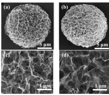
Figure 2. (a), (b) The low-magnifcation SEM of TiO2 and TiO2/S composite. (c), (d) The high- magnifcation SEM of TiO2 and TiO2/S composite.
[image:3.596.159.441.362.441.2] [image:3.596.203.389.505.668.2][image:4.596.213.390.306.470.2]
dimeter is located in the range of 15-20 μm. Figure 2b is the SEM image of TiO2/S composites. It can be seen that the elemental sulfur is uniformly dispersed in the pores of TiO2 spheres. The morphology has no obvious change between TiO2 and TiO2/S composites. Figure 2c and d further display the high- magnifcation SEM images of TiO2 and TiO2/S composite. As observed from the Figure, the surface of TiO2 and TiO2/S composite is consisted many nano-sheets. These nano-sheets provide adequate active site for the electrochemical reaction during discharge-charge process of TiO2/S composite cathode in the Li-S batteries.
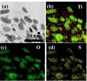
Figure 3a is the high- magnifcation TEM image of the TiO2/S composite. From the Figure 3a, the TEM image indicates the nano-sheet morphology. This is consistent with the SEM results. To confirm the presence of all elements in the TiO2/S composite, corresponding elemental mapping of TiO2/S composite was applied. As shown in Figure 3b, c and d, the elements Ti, O and S are uniformly distributed in the whole TiO2/S composite.
Figure 3. (a) The high- magnifcation TEM image of TiO2/S composite, corresponding elemental mapping of TiO2/S composite (b) Ti, (c) O, (d) S.
Figure 4. The XRD pattern of the TiO2 spheres and TiO2/S composites at 2 theta from 10° to 80°.
[image:4.596.218.378.538.666.2]
literature [16]. After heated with the sulfur, the peaks of TiO2/S composites are similar with the pure sulfur. This is because the diffraction peaks of sulfur are very strong. Therefore, the XRD pattern of TiO2/S composite mainly exhibits the peaks of sulfur. In all, these results confirm the successful preparation of TiO2/S composite.
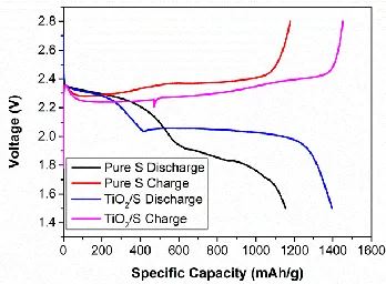
[image:5.596.211.385.292.420.2]The electrochemical performances are the key index for measuring the as-prepared TiO2/S composite. The first discharge/charge profiles are tested at the current density of 0.1C. As shown in Figure 5, the profiles of TiO2/S and pure S are similar. Both of them have two voltage platforms during the discharge process at 2.3 V and 2.1 V, respectively. Besides, the other information could be obtained from the profiles. The specific capacity value of TiO2/S composites is much higher than the pure sulfur. The value of TiO2/S composites is 1405 mAh g-1 at the current density of 0.1 C. This result confirms the positive effect of TiO2 in the TiO2/S composites for improving the specific capacity value of the cathode materials [17, 18].
Figure 5. The DC curves of pure S and TiO2/S composites at the current density of 0.1 C. Figure 6a shows the cycle stability of two cathode materials at the current density of 0.5 C. The TiO2/S composite exhibits capacity value of 1102 mAh g-1. After 100 cycles, the capacity value is remained at 968 mAh g-1, which demonstrating excellent cycle performance at the high current density. In terms of the pure S cathode, the capacity value is 1051 mAh g-1 before cycling. This value is only 882 mAh g-1 after 100 cycles. Even at much higher current density, the TiO
2/S composite cathode could keep superior cycle stability. As shown in Figure 6b, it exhibits the capacity retention of two cathode materials at higher current density, it can be clearly seen that the TiO2/S composite have high capacity retention of 96%. While the capacity retention of pure S fades rapidly with the improvement of cycles. As for the reason of improvement of TiO2/S composite cathode, it is mainly attributed to the uniformly distribution of sulfur in the composite cathode materials [19]. This is beneficial for the enhancement of cycle stability of the cathode in the Li-S battery [20]. However, the pure S cathode suffers from severe capacity fading during the cycles, which is caused by the poor electronic conductivity and dissolution of polysulfide [21]. For the TiO2/S cathode, the metal oxide TiO2 could deal with these problems at the same time.
Figure 6. (a) The comparison of cycle performance for TiO2/S and pure S at the current density of 0.5 C. (b) The capacity retention of two cathode materials at the current density of 0.5 C.
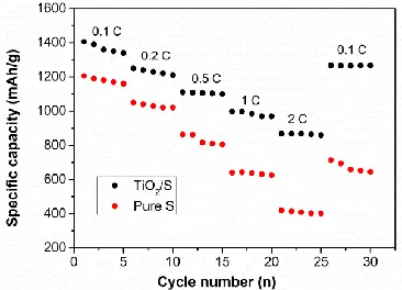
Rate performance is also an important index for judging the performance of the cathode materials. Based on this reason, a comparison of rate performance for the two cathode materials is made [22]. As shown in Figure 7, the specific capacity value of TiO2/S and pure S at various current densities from 0.1 C to 2C is exhibited in the Figure. It can be clearly observed that the TiO2/S composite cathode displays perfect rate performance. Even at the high current density of 2 C, the capacity value of TiO2/S is 852 mAh g-1. Moreover, the capacity value recovers the pristine value when the current density comes back to 0.1 C. This improved rate performance is ascribed to the presence of hierarchically constructed TiO2 spheres, which could inhibit the migration of polysulfide as an efficient polysulfide barrier. In all, the electrochemical performance of the Li-S batteries is greatly enhanced by using metal oxides TiO2 as absorber for the polysulfide [23].
Figure 7. The comparison of rate performance for TiO2/S and pure S at various current densities from 0.1 C to 2 C.
[image:6.596.131.470.76.206.2] [image:6.596.206.389.454.586.2]
Therefore, this work may provide a promising method for preparing superior cathode material for Li-S batteries.
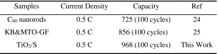
Table 1. The electrochemical performance of TiO2/S cathode compared with other cathode materials for the Li-S batteries.
Samples Current Density Capacity Ref
C60 nanorods 0.5 C 725 (100 cycles) 24
KB&MTO-GF 0.5 C 856 (100 cycles) 25
TiO2/S 0.5 C 968 (100 cycles) This Work
4. CONCLUSIONS
In summary, novel hierarchically constructed TiO2 spheres are prepared and used host materials for sulfur cathode. This novel structure of TiO2 spheres serves as the host material, which could efficiently stabilize the polysulfide at the cathode side. As a result, the TiO2/S composites exhibit excellent cycle stability and rate performance. The first specific capacity value is 1405 mAh g-1 at the current density of 0.1 C. The capacity value is 968 mAh g-1 at the current density of 0.5 C after 100 cycles. Even at the high current density of 2 C, the capacity value of TiO2/S is 852 mAh g-1.
ACKNOWLEDGEMENT
This work was supported by the Major National Science and Technology Projects (2017ZX04011010).
References
1. Y. P. Huang, X. G. Sun, J. Wang, X. Li, W. Chen, C. C. Wei, H. Hu and G. D. Liang, J. Alloy Compd., 776 (2019) 187.
2. J. Ni, L. M. Jin, M. Z. Xue, J. S. Zheng, J. P. Zheng and C. M. Zhang, Electrochim. Acta, 296 (2019) 39.
3. Y. L. An, Y. Tian, H. F. Fei, G. F. Zeng, H. W. Duan, S. C. Zhang, P. Zhou, L. J. Ci and J. K. Feng, Mater. Lett., 228 (2018) 175.
4. R. L. Yang, H. W. Du, Z. Q. Lin, L. L.Yang, H. Zhu, H. Zhang, Z. K. Tang and X. C. Gui, Carbon, 141 (2019) 258.
5. L. Y. Du, Q. Wu, L. J. Yang, X. Wang, R. C. Che, Z. Y. Lyu, W. Chen, X. Z. Wang and Z. Hu, Nano Energy, 57 (2019) 34.
6. X. H. Wang, Z. Wang, L. Z. Wang, Z. Q. Wang and H. Z. Guo, J. Power Sources, 414 (2019) 318. 7. Q. S. Wang, L. H. Jiang, Y. Yu and J. H. Sun, Nano Energy, 55 (2019) 93.
8. X. L. Lu, Q. F. Zhang, J. Wang, S. H. Chen, J. M. Ge, Z. M. Liu, L. L. Wang, H. B. Ding, D. C. Gong, H. G. Yang and B. G. Lu, Chem. Eng. J., 358 (2019) 955.
9. Y. P. Huang, X. G. Sun, J. Wang, X. Li, W. Chen, C. C. Wei, H. Hu and G. D. Liang, J. Alloy Compd., 776 (2019) 187.
10.R. H. Zhang, T. S. Zhao, H. R. Jiang, M. C. Wu and L. Zeng, J. Power Sources, 409 (2019) 76. 11.Y. Li, J. Chen, Y. F. Zhang, Z. Y. Yu, T. Z. Zhang and L. P. Zhang, J. Alloy Compd., 766 (2018)
[image:7.596.122.477.162.250.2]
12.Y. Q. Wang, S. Q. Luo, D. Q. Wang, X. B. Hong and S. K. Liu, Electrochim. Acta, 284 (2018) 400. 13.N. Li, X. He, K. H. Chen, S. Y. Chen and F. Y. Gan, Mater. Lett., 228 (2018) 195.
14.N. Liu, L. Wang, Y. Zhao, T. Z. Tan and Y. G. Zhang, J. Alloy Compd., 769 (2018) 678. 15.J. Wang, C. M. Fu, X. F. Wang, Y. M. Yao, M. L. Sun, L. N. Wang and T. X. Liu, Electrochim.
Acta, 292 (2018) 568.
16.X. Y. Wen, K. X. Xiang, Y. R. Zhu, L. Xiao, X. H. Chen and H. Chen, Mater. Lett., 229 (2018) 272. 17. P. H. Shao, J. Y. Tian, F. Yang, X. G. Duan, S. S. Gao, W. X. Shi, X. B. Luo, F. Y. Cui, S. L. Luo
and S. B. Wang, Adv. Funct. Mater., 28 (2018) 1705295.
18.Q. Sun, Y. Yang, Z. Zhao, Q. Zhang, X. Zhao, G. Nie, T. Jiao and Q. Peng, Environ. Sci: Nano, 5 (2018) 2440.
19. X. Y. Min, X. Wu, P. H. Shao, Z. Ren, L. Ding, X. B. Luo, Chem. Eng. J., 358 (2019) 321.
20. N. Li, S. F. Tang, Y. D. Rao, J. B. Qi, Q. R. Zhang and D. L. Yuan, Electrochim. Acta, 298 (2019) 59.
21. H. Y. Yu, P. H. Shao, L. L. Fang, J. J. Pei, L. Ding, S. G. Pavlostathis and X. B. Luo, Chem. Eng. J., 359 (2019) 176.
22. S. F. Tang, D. L. Yuan, Y. D. Rao, M. H. Li, G. M. Shi, J. M. Gu and T. H. Zhang. J. Hazard. Mater., 366 (2019) 669.
23. R. Mezzenga, Q. R. Zhang, S. Bolisetty, Y. P. Cao, S. Handschin, J. Adamcik and Q. M. Peng, Angew. Chem. Int. Edit., 2019, Doi: 10.1002/anie.201901596.
24. Y. L. An, Y. Tian, H. F. Fei, G. F. Zeng, H. W. Duan, S. C. Zhang and J. K. Feng, Mater. Lett., 228 (2018) 175.
25. S. Lin, Y. R. Cai, J. Yang, F. X. Ruan, J. Wu, B. B. Sireesh, Y. Xin and J. M. Yao, J. Alloy Compud., 779 (2019) 412.