Int. J. Electrochem. Sci., 14 (2019) 11178 – 11188, doi: 10.20964/2019.12.51
International Journal of
ELECTROCHEMICAL
SCIENCE
www.electrochemsci.org
Electrocatalytic dechlorination of p-chlorophenol using a 3D
cathode with magnetic separable Fe3O4@PPy@Pd catalyst
Xuefeng Wei*, Laiyuan Zeng, Juan Miao, Ruichang Zhang, Junjie Zhang, Shuai An, Jun Zhang
College of Chemical Engineering & Pharmaceutics, Henan University of Science and Technology, Luoyang, 471023, P.R. China
*E-mail: [email protected]
Received: 20 June 2019 / Accepted: 27 August 2019 / Published: 29 October 2019
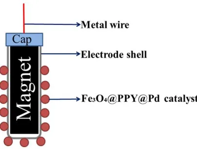
The magnetic separable catalyst, Fe3O4@PPy@Pd, was successfully prepared and characterized by scanning electron microscopy (SEM), X-ray diffraction (XRD), and inductively coupled plasma-atomic emission spectroscopy (ICP-AES). The three dimensional (3D) composite electrode was fabricated by loading the Fe3O4@PPY@Pd catalyst onto a permanent magnet core@Ti housing support. The electrocatalytic hydrodechlorination of p-chlorophenol on the 3D composite electrode in aqueous solutions was investigated, and the influences of initial pH, the applied current and the type of aeration on the dechlorination efficiencies of p-chlorophenol were also studied. The dechlorination efficiency reached 92.3% within 120 min, under optimum conditions, i.e., with a dechlorination current of 5 mA, a pH value of 2.35 and using a supporting electrolyte of 0.05 mol/L Na2SO4 at ambient temperature. The 3D composite electrode shows promising potential for dechlorination with good stability and reusability.
Keywords: electrocatalytic dechlorination; three-dimensional electrode; polypyrrole; magnetic separable catalysts
1. INTRODUCTION
technology [14] and so on. However, CPs are ineffectively broken down via biological and oxidative methods due to the presence of C−Cl bonds [4]. An efftive way to decrease the biotoxicity and eliminate the adverse effects of CPs is to convert chlorophenols into chlorine-free phenol and hydrogen chloride in the aqueous phase [15]. Among the methods listed above, electrocatalytic hydrogenation (denoted hereafter as ECH) has been regarded as a promising technology and has drawn the attention of many researches [4, 16-18], due to its mild reaction condition, ease of operation and lack of second pollution[19, 20]. During the ECH process, hydrogen atoms generated by the electrolysis of water are absorbed onto an electrode’s surface, which then cleave and add hydrogen to C-Cl bonds [3, 21-23].
The catalyst plays an important role in the electric catalysis reaction, which will affect the efficiency of ECH. Recently, many noble mental catalysts, such as Pd [24], Pt [25], Ag [26], Rh [27] and Ni [28], have been applied in the catalytic hydrogenation of dechlorination [29]. In contrast, Pd is considered the ideal catalysts for the generation of atomic H* and absorption of H* into the Pd crystal lattice [22]. Therefore, numerous Pd-based composite catalysts, such as bimetallic catalysts (Pd/Fe [30], Pd/Ni [31], Pd/Ag [32], Pd/Al [33] and Pd/Cu [34]), non-metallic supported Pd catalysts (Pd/C [35], Pd/Y2O3 [36] and Pd/SiO2 [37]), and nonmagnetic, metallic oxide supported Pd catalysts (Pd/Al2O3 [38] and Pd/CeO2 [39]) have been investigated recently. It has been reported that metal nanoparticles have better ability for dechlorination [40] compared with the ablility of the bulk metals because of their larger surface-to-volume ratios. However, the separation methods for these catalysts such as filtration or centrifugation are difficult and time-consuming as the size of the supportdecreases [41].
Ferroferric oxide (Fe3O4) nanoparticles which are superparamagnetic property in nature can be easily separated from reaction solution with an external magnetic field [42], were used as a catalyst carrier to overcome these disadvantages [43]. Pd/Fe3O4 nanocomposites have been prepared by varying the stabilizer and their effect on ethanol electro-oxidation in alkaline media have been explored [44]. In spite of its advantages, this catalyst still has its weaknesses, such as the easy abscission of metal nanoparticals, which will decline the reactivity and reduce the cycle time of catalytic electrode resultantly [45]. As a result the Pd composite catalysts still need to be improved. Intergating metal catalyst carrier with a conducting polymer has been shown to be an effective means of promoting the dispersibility of mental nanoparticles [46]. Polypyrrole (PPy) has been shown promising results when used as the conductive polymer layer, owing to its easy preparation, high electrical conductivity and large surface area [47-49]. Moreover, already prepared composite electrodes which were modified by PPy, showed the high performance towards the dechlorination reaction [50-52].
2. EXPERIMENTAL 2.1 Materials
Pd chloride (PdCl2, >95%) powder, ferric trichloride (FeCl3▪6H2O), ferrous sulfate (FeSO4▪7H2O), ammonium hydroxide (NH3▪H2O), sodium dodecyl benzene sulfonate (SDBS) were of analytical grade and purchased from Tianjin Deen Chemical Reagents Co. Ltd., China. Pyrrole and p-chlorophenol (>99%) of analytical grade were supplied by Sinopharm Chemical Reagent Co. Ltd., China. The other chemicals (NaBH4, HCl, H2SO4, etc.) obtained from Luoyang Haohua Chemical Reagents Co. Ltd. (Luoyang, China) were of analytical reagent grade and used without further purification. Millipore-Q water was used throughout all the experiments.
2.2 Experimental procedures 2.2.1 Synthesis of catalysts
The Fe3O4@PPy@Pd catalyst was prepared as reported our previous work [53]. First, a certain amount of FeCl3·6H2O and FeSO4·7H2O were dissolved in deionized water. Subsequently, 20 mL NH3·H2O was added dropwise to the mixture solution and then stirred for 1 h. The products were collected and then washed with water and ethanol and dried in an air oven at 60 ℃ for 12 h to obtain the Fe3O4 matrix. Second, 0.2 g of Fe3O4 nanoparticles were re-dispersed in 60 mL of distilled water using ultrasonication, followed by the addition of 0.35 mL pyrrole monomer and 20 mL of 5 mM SDBS. Then, 50 mL of 0.3 mol/L FeCl3 was added to the above mixed solution using mechanical agitating for 1 h. The black precipitate was washed repeatedly with deionized water to remove the residue that were then collected by means of a magnet and then dried in an air oven to get Fe3O4@PPy. Finally, 35.6 mg of the Fe3O4@PPy powder was dispersed in a 25 mL of distilled water via ultrasonication. The homogeneous solution was stirred with 5 mL of 10 mmol/L PdCl2 solution for 30 min, and an excess of freshly prepared NaBH4 solution was slowly dropped into the above mixture with vigorous stirring for another 1 h at room temperature. The product was separated with the help of magnet, washed thoroughly with deionized water until the supernatant became colorless and then dried in an air oven to obtain the Fe3O4@PPy@Pd catalysts.
2.2.2 Preparation of 3D electrode
Figure 1. Schematic diagram of the 3D electrode structure.
2.2.3 Dechlorination experiments
The electrocatalytic hydrodechlorination of p-chlorophenol was carried out in a two-compartment cell, separated by a Nafion-117 cation-exchange membrane to prevent Cl- produced at the cathode cell from flowing and generating Cl2 at the anode [54]. A Pt plate (20 mm × 20 mm × 0.5 mm) and the 3D composite electrode were used as the anode electrode and working electrode, respectively. The catholyte contained 40 mL of 100 mg/L p-chlorophenol and 0.05 mol/L of Na2SO4. The anolyte was 40 mL 0.05 mol/L of Na2SO4. Constant current was applied using a direct-current supply source (KEITHLEY, 2200S-901-01D, USA). At 20-minute interval times, a 1 mL sample was taken from the cathode compartment for further analysis.
2.3 Analytical methods
The concentration of p-chlorophenol and its dechlorination product were monitored by high performance liquid chromatography (HPLC, Waters, USA) with a TC-C18 column (4.6 mm × 250 mm, 5 μm) and a UV detector with a column temperature of 30 ◦C. The mobile phase was 30:70 (v/v) mixture of methanol: 2% acetic acid solution, and the flow rate was 0.8 mL/min and the wavelength was 280 nm. It is worth noting that the mobile phase was first sonicated to remove dissolved gas and then filter to remove any impurities.
The morphological characteristics of the movable catalysts were observed using a scanning electron microscope (SEM, Hitachi SU8010, Japan). The crystal structure and states of the catalysts were detected by a Bruker/AXS model D8 Advance X-ray diffractometer (XRD) with Co Ka radiation respectively. Inductively coupled plasma-atomic emission spectroscopy (ICP-AES, RIS Intrepid ER/S, Thermo Elemental, USA) was employed to detect the content of Pd in catalysts.
3. RESULTS AND DISCUSSION 3.1. Characterization
[image:4.596.209.411.80.233.2]
catalyst exhibits a uniform, three-dimensional spherical structure. Magnified images reveal that the surface of the Fe3O4@PPy@Pd composite is rather rough (Figure 2b) and looks similar to a cauliflower, which may provide more active sites, in favour of the catalytic reaction.
Figure 2. SEM images of Fe3O4@PPy@Pd catalyst, (a) 10,000×, (b) 50,000×.
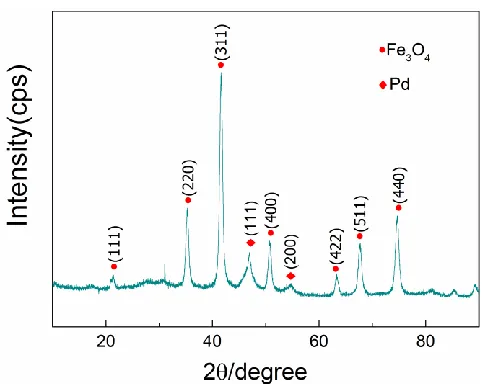
The crystal structure of the Fe3O4@PPy@Pd composite catalyst was characterized by XRD and the results are shown in Figure 3. For the above-synthesized catalyst, the diffraction peaks at 2θ=21.464◦, 35.406◦, 41.780◦ 50.940◦, 63.564◦, 67.924◦, and 74.915◦ can be assigned to the (111), (220), (311), (400), (422), (511), and (440) crystal planes of Fe3O4(JCPDS No.75-0449), respectively. The other two diffraction peaks at 2θ=47.056◦ and 54.898◦ belong to the (111) and (220) crystal planes of Pd (JCPDS No.87-0639), respectively. The XRD results showed that Pd nanoparticles were successfully loaded onto the carrier with crystallite sizes of 14.8 nm according to the Scherrer equation.
[image:5.596.71.525.140.312.2] [image:5.596.179.420.524.716.2]
Inductively coupled plasma-atomic emission spectroscopy (ICP-AES) was also employed to detect the content of the Pd catalysts. The results showed that the Pd loading of the Fe3O4@PPy@Pd composite catalyst was 6.45%.
3.2. Effect of the initial pH value
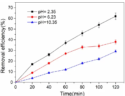
[image:6.596.181.420.275.459.2]The effects of the initial pH on the electrocatalytic dechlorination was also investigated. Dilute sulfuric acid and sodium hydroxide were added to adjust the pH value of the solution. Aeration with a blowing rate of 0.1 Nm3/h was employed to mix the solution. Dechlorination experiments were carried out at a current of 5 mA. The results are shown in Figure 4.
Figure 4. Removal efficiency of p-chlorophenol at different initial pH values, I = 5 mA.
As shown in Figure 4, the removal efficiency of p-chlorophenol increased with reaction duration increased. The initial pH also has a clear influence on the dechlorination reaction. The removal efficiency of p-chlorophenol was 29.2%, 38.4% and 62.3% at 120 min for pH values of 10.35, 6.23 and 2.35, respectively. The conversion rate of p-chlorophenol for the acidic condition was higher than that in alkaline condition. The ECH is a pH- dependency process, and it proceeded rapidly with a lower apparent activation energy (Ea) in the acidic electrolyte due to the protonation. This result is in consistent with the literatures [52, 55].
3.3. Effects of the applied current
[image:7.596.180.419.154.342.2]
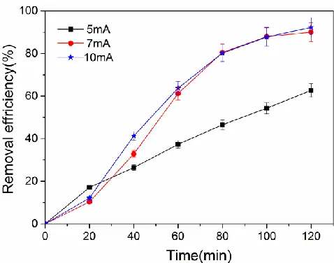
of 0.1 Nm3/h, and the pH of catholyte was maintained at 2.35 by adjusting with dilute sulfuric acid during the electrocatalytic process.
Figure 5 Removal efficiency of p-chlorophenol at different current values. pH =2.35.
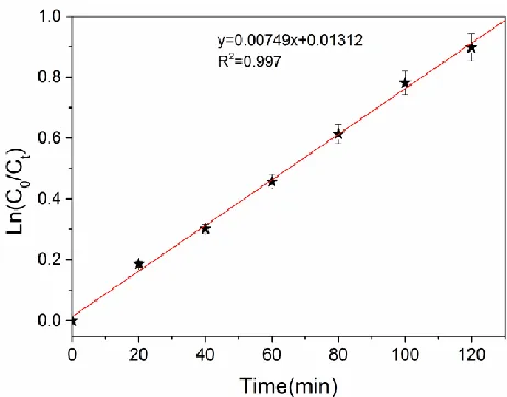
Figure 5 shows the relationship between the removal efficiency of 4-chlorophenol and the reaction time for different constant current. The removal efficiency of p-chlorophenol was 62.7% for a reaction time of 120 min at a constant current of 5 mA, which was probably due to insufficient production of reductive substances at low currents [52]. In comparison, the dechlorination efficiency reached 90% and 92.3% for reaction time of 120 min with current values of 7 mA and 10 mA, respectively. However, when the current rose from 7 mA to 10 mA, the dechlorination efficiency only increased slightly. In light of the energy consumption during dechlorination, 7 mA was considered to be the optimum current in this experiment.
Figure 6. Plot of ln(C0/Ct) versus t of p-chlorophenol dechlorination, pH =2.35, I = 7 mA. 3.4. Effects of the type of aeration
[image:8.596.179.420.469.658.2]Blast aeration was used instead of magnetic stirring to avoid magnetic nanoparticles adsorbing on the magneto and affecting the catalytic effect of the electrode in this experiment. Two different gases, nitrogen and oxygen, were injected into the cathode chamber at flow rates of 0.1 Nm3/h to investigate the influence of the type of blast aeration on electrocatalytic dechlorination. To maintain the acidity of the solution, 0.2 mL of sulfuric acid (0.5 mol/L) was added to the solution every 0.5 h during the reaction process. The results of the p-chlorophenol dechlorination reaction are shown in Figure 7.
Figure 7. Removal efficiency of p-chlorophenol at different aeration types.
much higher than that of nitrogen. The removal of p-chlorophenol was 56.3% and 92.3% after 120 min while injecting nitrogen and oxygen into the catholyte, respectively. It was speculated that hydroxyl radical (▪OH) or other active species were generated when oxygen was bubbled into the catholyte [57, 58], which enhanced the conversion of p-chlorophenol.
3.5. Stability of the electrode
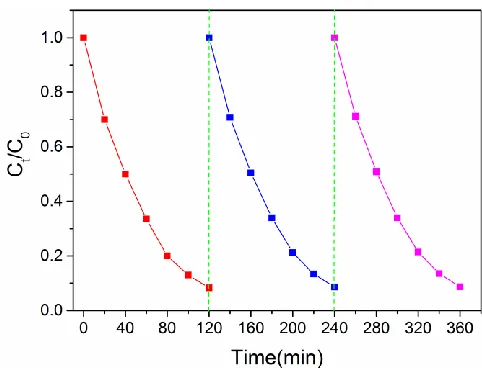
To examine the stability and reusability of the 3D composite electrode, 3 consecutive experiments were performed under the same experimental conditions. As shown in Figure 8, the dechlorination efficiency of p-chlorophenol for the 3rd cycle decreased slightly in comparison with the first cycle which demonstrated the good stability and reusability of the Fe3O4@PPy@Pd loaded 3D electrode for the ECH of p-chlorophenol. To some extent, the strong adsorption between magnetic separable catalysts and the magnet enhanced the stability of the 3D composite electrode.
Figure 8. The dechlorination of 4-CP for three reaction cycles using the 3D composite electrode.
4. CONCLUSION
[image:9.596.178.419.309.493.2]
ACKNOWLEDGMENTS
This work was supported by National Natural Science Foundation of China (21403058, 21576073, and 41601520), and Research Foundation for the Young Core Instructor Program of Henan Province, China (2016GGJS-058).
References
1. P. Wu, G.-P. Yang and X.-K. Zhao, J. Colloid Interface Sci., 265(2003) 251. 2. Z. R. Sun, G. Song, R. Du and X. Hu, Rsc Advances, 7(2017) 22054.
3. C. Jiang, H. Yu, X. Wang, Y. Lu and X. Luo, Int. J. Electrochem. Sc., 12(2017) 5208.
4. X. Y. She, Q. Yang, F. B. Yao, Y. Zhong, W. C. Ren, F. Chen, J. Sue, Y. H. Ma, Z. Y. Fe, D. B. Wang and X. M. Li, Chem.Eng.J., 358(2019) 903.
5. T. Gan, Z. K. Wang, J. Y. Gap, J. Y. Sun, K. B. Wu, H. B. Wang and Y. M. Liu, Sens. Actuators, B-Chem., 282(2019) 549.
6. C. S. Jiang, H. B. Yu, Y. Lu, S. Y. Zhu, Z. Geng, M. X. Huo and X. H. Wang, Thin Solid Films, 664(2018) 27.
7. S. Y. Cho, O. S. Kwean, J. W. Yang, W. Cho, S. Kwak, S. Park, Y. Lim and H. S. Kim, Bioresour. Technol., 245(2017) 1800.
8. J. X. Song, Q. Zhao, J. Guo, N. Yan, H. D. Chen, F. F. Sheng, Y. J. Lin and D. An, Sci. Total Environ., 651(2019) 1368.
9. N. U. Garcia-Cruz, G. Vigueras, N. A. Pacheco-Lopez, A. Zepeda-Pedreguera and M. A. Lizardi-Jimenez, Biochem. Eng. J., 139(2018) 117.
10.C. Y. Chen, X. H. Geng and W. L. Huang, Chem. Eng. J., 327(2017) 941.
11.T. J. Yoon, H. L. Shao, R. Weissleder and H. Lee, Part. Part. Syst. Char., 30(2013) 667. 12.K. Rusevova, F. D. Kopinke and A. Georgi, J. Hazard. Mater., 241(2012) 433.
13.J. Wang, Y. Xia, H. Y. Zhao, G. F. Wang, L. Xiang, J. L. Xu and S. Komarneni, Appl. Catal. B-Environ., 206(2017) 406.
14.G. M. Jiang, K. F. Wang, J. Y. Li, W. Y. Fu, Z. Y. Zhang, G. Johnson, X. S. Lv, Y. X. Zhang, S. Zhang and F. Dong, Chem. Eng. J., 348(2018) 26.
15.J. Andersin, P. Parkkinen and K. Honkala, J. Catal., 290(2012) 118.
16.S. Jung, A. N. Karaiskakis and E. J. Biddinger, Catal. Today, 323(2019) 26.
17.U. Sanyal, J. Lopez-Ruiz, A. B. Padmaperuma, J. Holladay and O. Y. Gutierrez, Org. Process Res. Dev., 22(2018) 1590.
18.J. A. Lopez-Ruiz, U. Sanyal, J. Egbert, O. Y. Gutierrez and J. Holladay, Acs Sustainable Chem. Eng., 6(2018) 16073.
19.A. Z. Li, X. Zhao, Y. N. Hou, H. J. Liu, L. Y. Wu and J. H. Qu, Catal. B-Environ., 111(2012) 628. 20.R. Mao, N. Li, H. C. Lan, X. Zhao, H. J. Liu, J. H. Qu and M. Sun, Environ. Sci. Technol., 50(2016)
3829.
21.J. Li, H. Wang, L. Wang, C. Ma, C. Luan, B. Zhao, Z. Zhang, H. Zhang, X. Cheng and J. Liu, Catalysts, 8(2018) 378.
22.G. M. Jiang, M. N. Lan, Z. Y. Zhang, X. S. Lv, Z. M. Lou, X. H. Xu, F. Dong and S. Zhang, Environ. Sci. Technol., 51(2017) 7599.
23.G. Chen, Z. Wang, T. Yang, D. Huang and D. Xia, J. Phys. Chem. B, 110(2006) 4863.
24.W. Y. Fu, K. F. Wang, X. S. Lv, H. L. Fu, X. G. Dong, L. Chen, X. M. Zhang and G. M. Jiang, Chinese J. Catal., 39(2018) 693.
25.K. Tsutsumi, F. Uchikawa, K. Saka and K. Tabata, Acs Catalysis, 6(2016) 4394.
Technol., 46(2012) 4576.
29.C. Bradu, C. Capat, F. Papa, L. Frunza, E. A. Olaru, G. Crini, N. Morin-Crini, E. Euvrard, I. Balint, I. Zgura and C. Munteanu, Appl. Catal. A-General, 570(2019) 120.
30.A. Ghauch and A. Tuqan, J. Hazard. Mater., 164(2009) 665.
31.S. Wang, B. Yang, T. T. Zhang, G. Yu, S. B. Deng and J. Huang, Ind. Eng. Chem. Res., 49(2010) 4561.
32.J. D. Zuo, Y. Y. Song and Z. B. Sun, Nanotechnology, 30(2019)9.
33.F. Cazana, A. Galetti, C. Meyer, V. Sebastian, M. A. Centeno, E. Romeo and A. Monzon, Catal. Today, 301(2018) 226.
34.H. Han, S.-D. Yang and J.-B. Xia, J. Org. Chem., 84(2010) 3357. 35.Y. Kim and D. H. Kim, Appl. Catal. B-Environ., 244(2019) 684.
36.J. X. Li, S. L. Wang, B. G. Zhang, W. Wang and L. G. Feng, Int. J. Hydrogen Energy, 42(2017) 12236.
37.J. S. Kwon, J. S. Kim, H. S. Lee and M. S. Lee, J. Nanosci. Nanotechnology., 19(2019) 882. 38.G. Celik, S. A. Ailawar, S. Gunduz, P. L. Edmiston and U. S. Ozkan, Catal. Today, 323(2019) 129. 39.Z. G. Hu, G. L. Zhou, L. Xu, J. H. Yang, B. Zhang and X. Xiang, Appl. Surf. Sci., 471(2019) 852. 40.H. Feng and D. Zhao, Appl. Catal. B-Environ., 84(2008) 533.
41.J. Xu, J. Tang, S. A. Baig, X. S. Lv and X. H. Xu, J. Hazard. Mater., 244(2013) 628.
42.N. D. Banic, B. F. Abramovic, J. B. Krstic, D. V. S. Merkulov, N. L. Fincur and M. N. Mitric, J. Ind. Eng. Chem., 70(2019) 264.
43.R. Das, V. S. Sypu, H. K. Paumo, M. Bhaumik, V. Maharaj and A. Maity, Appl. Catal. B-Environ., 244(2019) 546.
44.H. Rivera-Gonzalez, L. Torres-Pacheco, L. Alvarez-Contreras, A. Oliva, M. Guerra-Balcazar, R. Valdez and N. Arjona, J. Electroanal. Chem., 835(2019) 301.
45.T. J. Yao, T. Y. Cui, H. Wang, L. X. Xu, F. Cui and J. Wu, Nanoscale, 6(2014) 7666.
46.J. Liu, X. J. Mu, Y. M. Yang, F. J. Chen, J. G. Wang, Y. E. Li and B. D. Wang, Appl. Catal. B-Environ, 244(2019) 356.
47.D. Chowdhury, A. Paul and A. Chattopadhyay, Langmuir : the ACS journal of surfaces and colloids, 21(2005) 4123.
48.Y. C. Yang, J. W. Wen, J. H. Wei, R. Xiong, J. Shi and C. X. Pan, ACS Appl. Mater. Inter., 5(2013) 6201.
49.L. Zhang, L. Peng and Z. Su, Polym. Degrad. Stab., 91(2006) 2213.
50.Z. R. Sun, X. F. Wei, Y. B. Han, S. Tong and X. Hu, J. Hazard. Mater., 244(2013) 287. 51.Z. R. Sun, H. T. Shen, X. F. Wei and X. Hu, Chem. Eng. J., 241(2014) 433.
52.Z. R. Sun, X. F. Wei, H. T. Shen and X. Hu, Electrochim. Acta, 129(2014) 433.
53.X. F. Wei, X. Y. Wan, J. Miao, R. C. Zhang, J. Zhang and Q. J. Niu, Catal. Lett., 149(2019) 823. 54.W. Xie, S. Yuan, X. Mao, W. Hu, P. Liao, M. Tong and A. N. Alshaulabkeh, Water Res., 47(2013)
3573.
55.X.F. Wei, X.Y. Wan, Z.R Sun, J Miao, R.C. Zhang and Q. J. Niu, ACS Omega, 5(2018), 5876. 56.X.F. Wei and Z.R. Sun, China Environmental Science, 34(2014) 2285.
57.J. Niu , Y. Bao, Y. Li and Z. Chai, Chemosphere, 92 (2013) 1571.
58.D.D. Xu, Y. Wang, H.Wang and Z.Y.Bian, Int. J. Electrochem. Sci., 12 (2017) 6445.