This is a repository copy of
Design, construction, and testing of an aero-engine
starter-generator for the more-electric aircraft
.
White Rose Research Online URL for this paper:
http://eprints.whiterose.ac.uk/146725/
Version: Published Version
Article:
Balachandran, A., Boden, M., Sun, Z. et al. (3 more authors) (2019) Design, construction,
and testing of an aero-engine starter-generator for the more-electric aircraft. The Journal
of Engineering, 2019 (17). pp. 3474-3478. ISSN 2051-3305
https://doi.org/10.1049/joe.2018.8235
[email protected]
https://eprints.whiterose.ac.uk/
Reuse
This article is distributed under the terms of the Creative Commons Attribution (CC BY) licence. This licence
allows you to distribute, remix, tweak, and build upon the work, even commercially, as long as you credit the
authors for the original work. More information and the full terms of the licence here:
https://creativecommons.org/licenses/
Takedown
If you consider content in White Rose Research Online to be in breach of UK law, please notify us by
The Journal of Engineering
The 9th International Conference on Power Electronics, Machines and
Drives (PEMD 2018)
Design, construction, and testing of an
aero-engine starter-generator for the more-electric
aircraft
eISSN 2051-3305
Received on 26th June 2018 Accepted on 30th July 2018 doi: 10.1049/joe.2018.8235 www.ietdl.org
Ajith Balachandran
1, Mark Boden
1, Zhigang Sun
1, Stephen J. Forrest
2, Jason D. Ede
2, Geraint. W.
Jewell
21Rolls-Royce Electrical, UK
2Rolls Royce University Technology Centre in Advanced Electrical Machines, The University of Sheffield, UK
E-mail: [email protected]
Abstract: This study describes the design, construction, and testing of an aero-engine starter-generator and its associated power electronic converter. A high-speed, permanent magnet machine and a dual-channel machine-facing converter with an electrical power offtake rating of 95 kW have been developed for a small civil turbofan application. The study also describes the more-electric architecture into which the machine and converter are integrated and reviews the multi-faceted performance specification, which is a common feature of machines of this type.
1 Introduction
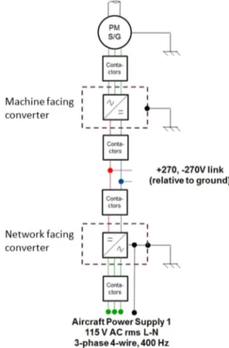
This paper describes the design, construction, and testing of an aero-engine starter-generator and its associated power electronic converter. A high-speed, dual-channel permanent magnet machine and a machine-facing converter have been developed for a small civil turbofan application [1]. The overall architecture of the electrical system into which the starter-generator and the machine-facing converter are incorporated along with a network-machine-facing converter and various network elements is shown in Fig. 1. This generation system is designed to deliver a continuous power rating of 95 kW into the DC network while in the generation mode. In the starting mode, the machine is expected to produce 50 N m of starting torque to drive the engine.
The machine was originally specified with continuous mechanical input power in the generator mode of 105 kW so that an output power of at least 100 kW could be realised when the
generator losses are accounted for. Similarly, the machine-facing converter was designed for a 100 kW electrical input power in order to provide a minimum of at least 95 kW of output power to the DC network. Power could be delivered directly to the engine accessories via this DC network. Alternatively, a network-facing converter could be used to provide power to the aircraft 115 VAC network (where required). In addition to the continuous rating, the system requirements are such that in combination, they must provide 1.25 times the rated current for up to 5 min and a 1.5 times the rated current for 5 s.
In the generation mode, the starter-generator and the machine-facing converter in combination provide a regulated ±270 V DC bus.
The machine is equipped with a direct oil-cooled stator winding and the resulting heat-transfer capability allows the machine to be designed on the basis of a continuous rms current density of 10–12 A/mm2. This conservative current density for a machine with direct oil-cooled windings is necessary to accommodate an onerous oil inlet temperature of 115°C. In addition to the high electric loading, cobalt–iron stator and rotor cores are used to achieve a high power density.
2 Machine design selection
Starter-generator designs employing several different pole numbers were investigated systematically and it became apparent that higher pole numbers were favoured in terms of power density, albeit at the expense of increased core losses. In order to accommodate the rated current limitations of the power modules selected for the converter and to provide a modest degree of fault accommodation, the machine was dual wound so as to split the machine into two power channels.
This necessitated using an even number of pole pairs in order to maintain the appropriate symmetry for the splitting of the stator winding into two separate power channels, i.e. either 4-pole, 8-pole, 12-pole etc. An 8-8-pole, 12-slot design was selected as it provided the best trade-off in terms of power density and core loss. In splitting the machine into two channels care was taken to ensure that the machine remained balanced from an electromagnetic perspective. A cross-section through the machine design along with the two-power channel configuration of the 12-numbered coils is shown in Fig. 2.
In refining the design of the selected slot/pole combinations, the design objectives were to minimise the mass of machine, while retaining a high efficiency and ensuring that the maximum speed
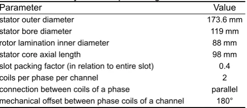
[image:2.595.80.244.508.757.2]and the short-term 1.5 times the power rating could be achieved within the voltage limits of the machine-facing converter. Repeated iterations using on-load, two-dimensional finite element simulations led to a stator core design with comparatively thin teeth and back iron, resulting in the Vacoflux 50 cobalt–iron operating at flux densities of up to 2.3 T. Table 1 summarises the final machine dimensions.
Fig. 3 shows the predicted phase back-emf waveforms for one of the channels and Fig. 4 shows the torque waveform at the 1.5 times the rated power at a speed of 14,677 rpm. The core losses at each operating condition were predicted using a series of magneto-static finite element calculations spanning one electrical cycle. The loss in each finite element of the stator and rotor cores was established from the predicted localised variation in flux density and a well-established loss separation model [2].
The resulting predictions of the machine copper and iron losses are shown in Table 2. As will be apparent, when operating at continuous power and base speed, these losses correspond to
∼1.5% of the electrical output power.
2.1 Machine design
The concentrated winding used in this 12-slot/8-pole machine has the very significant advantage of very compact and hence lower loss end-windings than a distributed winding counterpart. However, such windings can give rise to significant air gap field harmonics which in turn can cause problems with rotor losses generated by induced eddy currents. This is a particular concern in high-speed machines and often requires that each magnet pole is sub-divided, both axially and circumferentially and occasionally even radially, into many smaller segments. The prediction of the magnet eddy-current losses, particularly with axial sub-division of each magnet pole, requires magneto-dynamic three-dimensional finite element analysis in order to capture the highly three-dimensional nature of the eddy currents.
Fig. 5 shows the predicted eddy current losses for rated power at the maximum speed for various combinations of circumferential and axial segments across one pole. By way of interesting comparison, which demonstrates the value of three-dimensional finite element analysis, the corresponding loss predicted with two-dimensional magneto-dynamic finite element analysis for eight circumferential segments is 960 W for this operating point. On the
basis of the predicted rotor magnet loss, the final design comprised 8 circumferential and 30 axial segments per magnet pole, i.e.240 separate magnet pieces per pole.
In order to retain the rotor magnets in contact with the rotor core across the full speed range, a carbon fibre composite overwrap was employed. The complete rotor with the overwrap is shown in Fig. 6.
The wound stator is shown in Fig. 7 and the fully assembled machine in Fig. 8. Analyses of the active mass components, shown in Table 3, and the non-active components, shown in Table 4, indicate that despite efforts to reduce the mass of the aluminium casing and titanium rotor hub, only 53% of the overall weight is contributed by the active components.
2.2 Converter design
The combination of a predicted phase self-inductance of mere ∼36
H and a fundamental frequency of up to ∼1.8 kHz at the
maximum speed dictate that the converter must operate with a reasonably high switching to ensure manageable levels of ripple current. A switching frequency of 20 kHz was selected to meet this requirement. For the performance requirements set out in Table 5, there was a limited choice of commercially available power modules that could switch the required current at 20 kHz. This, in part, led to the selection of a two-channel topology, with each 50-kW channel based around hybrid power modules. The SKiM459GD12E5_SiC three-phase modules produced by Semikron consist of silicon IGBT switches with silicon carbide freewheeling diodes. Fig. 9 shows predicted comparison between the performance of this hybrid module and its standard all silicon counterpart at an rms current of 290 A. The power modules were controlled via Semikron SKYPER 42 LJ R gate driver boards, which in turn were controlled by a Texas Instruments F28335 board.
The power modules are attached to MQT1617 liquid-cooled heat sinks (manufactured by from MaxQ Technology). Each converter channel is equipped with a 500 F/700 V polypropylene
[image:3.595.327.548.48.194.2]Fig. 2 Selected 8-pole machine showing the dual-channel arrangement Table 1 Geometry of final 8-pole design
Parameter Value
stator outer diameter 173.6 mm
stator bore diameter 119 mm
rotor lamination inner diameter 88 mm stator core axial length 98 mm slot packing factor (in relation to entire slot) 0.4 coils per phase per channel 2 connection between coils of a phase parallel mechanical offset between phase coils of a channel 180°
Fig. 3 Phase back-emf waveform from 2D and 3D finite element analysis at the red line speed of 26,584 rpm
Fig. 4 Torque waveform for peak condition of 1.5 times the rated power at 14,677 rpm
[image:3.595.54.288.51.196.2] [image:3.595.44.288.231.338.2] [image:3.595.323.546.231.375.2]‘power-ring’ capacitor (700D50797-599 manufactured by SBC), which acts as a DC link capacitor. In order to remove capacitor losses, the top surface of the DC link capacitor was located in contact with the lower surface of the heat sink, separated by a compressible, self-adhesive, thermal interface, gap filler sheet (T Global H486-150-2.0A). The converter was equipped with insulated custom aluminium 6063 busbars. Fig. 10 shows the converter part way through assembly while Fig. 11 shows the fully assembled converter in a highly engineered casing. This converter,
[image:4.595.44.552.49.313.2]including all its casing, has a dry mass of 20 kg yielding a power density of 4.75 kW/kg at the rated power.
Table 2 Predicted copper and iron losses
Motoring loss, W Generating loss, W
14,677 rpm 26,584 rpm
7000 rpm 14,677 rpm rated 1.25 × rated 1.5 × rated rated 1.25 × rated 1.5 × rated
copper loss 620 141 1174 1864 2834 353 554 796
stator iron loss 110 238 307 350 389 556 589 626
rotor iron loss 7 16 22 28 36 36 37 40
total loss 737 395 1503 2242 3259 945 1180 1462
Fig. 5 Predicted magnet eddy current losses for sinusoidal currents at 26,584 rpm
Fig. 6 Completed rotor
Fig. 7 Wound stator in the casing
[image:4.595.313.552.60.315.2]Fig. 8 Completed machine
Table 3 Measured mass of active components
Active component Mass, kg
stator lamination stack 4.67
rotor lamination stack 1.29
stator windings (include slot-liner etc) 4.63 magnets and carbon fibre 1.56
[image:4.595.43.310.69.317.2]total mass 12.15
Table 4 Measured mass of non-active components Machine housing component Mass, kg
rotor shaft, washer, and captive nut 1.80
2-rotor endplates 0.18
rotor titanium hub 1.03
casing 3.69
DE endplate 1.22
NDE endplate 1.18
terminals, fixings, and connectors 1.51
[image:4.595.309.553.343.416.2]total 10.60
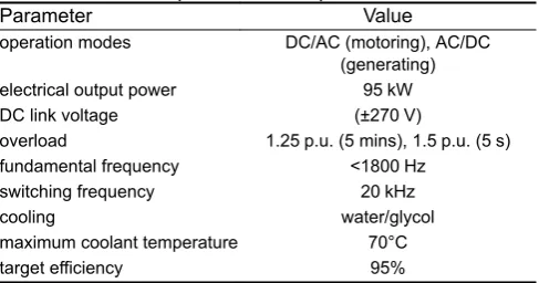
Table 5 Converter performance requirements
Parameter Value
operation modes DC/AC (motoring), AC/DC (generating) electrical output power 95 kW
DC link voltage (±270 V)
overload 1.25 p.u. (5 mins), 1.5 p.u. (5 s) fundamental frequency <1800 Hz
switching frequency 20 kHz
cooling water/glycol
maximum coolant temperature 70°C
[image:4.595.53.287.355.663.2] [image:4.595.309.553.444.551.2] [image:4.595.310.554.578.706.2]3 Experimental test results
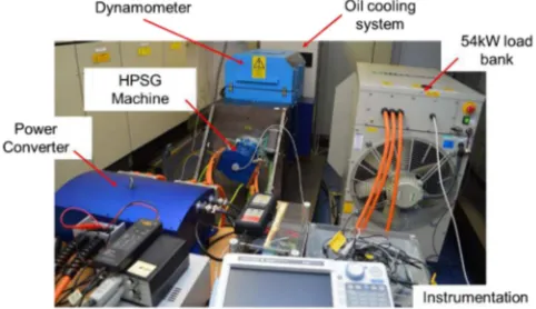
[image:5.595.317.555.47.228.2]The starter-generator and the machine facing converter combination was tested in two different test rigs. First, the basic functionality and low power testing in generating mode up to 50 kW were undertaken on an AVL APA120 dynamometer and a 54-kW resistive load bank connected across the DC link of the machine-facing converter. This test rig is shown in Fig. 12.
Fig. 13 shows measured currents and the DC link voltage when the machine and converter were operating in the generating mode at ∼15,000 rpm. The generating output power is divided almost
equally between the two channels.
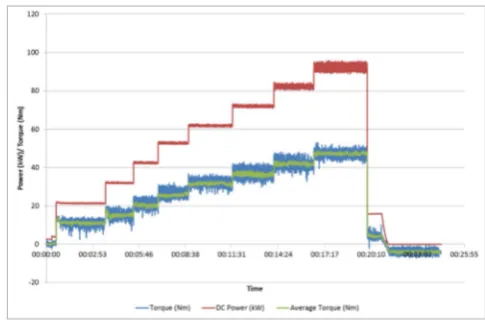
Full system testing of the starter-generator and the machine-facing converter was completed successfully at the Rolls-Royce electrical test facility in 2016. Fig. 14 shows the test setup used. The machine and converter were tested up to full-rated power in order to verify the design of the system. The measured DC link response along with the phase current of one of the channels, with the machine operating at its base speed, is shown in Fig. 15. Fig. 16 shows the power extracted from the machine at 19,000 rpm.
4 Conclusions
This paper has described the design, construction and testing of a 95-kW permanent magnet starter-generator and its associated power converter for an aero-engine. From the results presented above, it can be seen that the machine and the power converter can be operated up to its rated power as per the design intent.
[image:5.595.63.270.50.189.2]Fig. 9 Comparison of predicted losses for standard and hybrid modules
[image:5.595.48.288.215.352.2]Fig. 10 Power modules with drive boards
Fig. 11 Fully assembled converter with terminal box covers removed
Fig. 12 Test rig setup for commissioning and low power testing
[image:5.595.311.555.250.568.2]Fig. 13 Test results at 15,000 rpm with 49 kW output into the resistive load bank
Fig. 14 Test rig setup for the high power testing at Rolls-Royce
Fig. 15 Measured phase currents (channel 2) and DC link voltage, operating speed at 15,000 rpm and output power of 95 kW
[image:5.595.314.555.268.424.2] [image:5.595.47.289.318.501.2] [image:5.595.316.556.424.545.2] [image:5.595.44.285.538.677.2]5 Acknowledgments
The authors acknowledge the financial support of Rolls-Royce and Innovate UK (SILOET and IPPA programmes) to undertake this programme of research.
6 References
[1] Balachandran, A., Boden, M., Sun, Z., et al.: ‘The design and development of an electrical power offtake solution for a more-electric concept’. Proc. of MEA2017 More-Electric Aircraft, Bordeaux, February 2017
[2] Atallah, K., Zhu, Z.Q., Howe, D.: ‘An improved method for predicting iron losses in brushless permanent magnet DC drives’, IEEE Trans. Magn., 1992,
[image:6.595.47.290.47.207.2]28, (5), pp. 2997–2999