University of Southern Queensland
Faculty of Engineering and Surveying
Using sun observations to set an azimuth combining and
comparing Automatic Target Recognition in a Total Station with
GPS observed time and position
A project dissertation submitted by
Mr Phillip R. Nixon
B.SpaSci&Tec (Surveying) Dip Surveying
In the fulfillment of the requirements of
Course ENG4111/2 – Research Project
Towards the degree of
Bachelor of Spatial Science (Surveying)
ii 0050073010-Phillip Nixon - Project Dissertation - University of Southern Queensland 2011
i.
Abstract
The Leica 1200 series total stations have the ability to connect to a Differential Global Positioning Receiver (GPS) via Bluetooth. With a GPS mounted on the top of the Total Station, a position and height for a station can be obtained. The only other piece of information that is needed is the orientation.
The aim of this report is to investigate the potential for using Automatic Target Recognition (ATR) to take sun observations for the calculation of geodetic azimuths, to reduce pointing errors associated with solar observations.
A protective filter lens was constructed that enabled safe and functional tracking of the sun. Software was also written that calculates an azimuth in the field to assist with the testing of the accuracy of this method.
It was found that using the ATR tracking method on the sun was approximately twice as accurate when compared with the manual pointing method. The results of an averaged twelve set observation achieved results with a standard deviation of 12” over 11 observation periods, with a maximum error of 23”, when comparing the azimuth from the sun with the local geodetic control marks over a 350m baseline.
0050073010-Phillip Nixon - Project Dissertation - University of Southern Queensland 2011 iii
University of Southern Queensland
Faculty of Engineering and Surveying
ENG8411 & ENG8412
Research Project
.
Limitations of Use
The Council of the University of Southern Queensland, its Faculty of Engineering and Surveying, and the staff of the University of Southern Queensland, do not accept any responsibility for the truth, accuracy or completeness of material contained within or associated with this dissertation.
Persons using all or any part of this material do so at their own risk, and not at the risk of the Council of the University of Southern Queensland, its Faculty of Engineering and Surveying or the staff of the University of Southern Queensland.
This dissertation reports an educational exercise and has no purpose or validity beyond this exercise. The sole purpose of the course pair entitled “Research Project” is to contribute to the overall education within the student’s chosen degree program. This document, the associated hardware, software, drawings and other material set out in the associated appendices should not be used for any other purpose: if they are so used, it is entirely at the risk of the user.
Prof Frank Bullen
Dean
iv 0050073010-Phillip Nixon - Project Dissertation - University of Southern Queensland 2011
Certification
I certify that the ideas, designs and experimental work, results, analyses and conclusions set out in this dissertation are entirely my own effort, except where otherwise indicated and acknowledged.
I further certify that the work is original and has not been previously submitted for assessment in any other course or institution, except where specifically stated.
Phillip Richard Nixon
W0073010
_______________________________________
Signature
Sunday, October 02, 2011
_______________________________________
0050073010-Phillip Nixon - Project Dissertation - University of Southern Queensland 2011 v
ii.
Acknowledgements
The author wishes to acknowledge and thank the following people whose assistance made the completion of this Project Dissertation possible:
Zhenyu Zhang, Faculty of Engineering and Surveying, USQ; Dr Glenn Campbell, Faculty of Engineering and Surveying, USQ; Leigh Finlay, Sinclair Knight Merz;
Richard Ingham, C.R.Kennedy; Ann Nixon, honorary editor; Kerri Nixon, patient wife;
vi 0050073010-Phillip Nixon - Project Dissertation - University of Southern Queensland 2011
iii.
List of Figures
Figure 1 Using GPS combined with solar obseservation to reduce time when limited
observations per setup are required ... 5
Figure 2 Using GPS combined with solar observations to assist with relavtivly accurate setouts over large scale project ... 5
Figure 3 Using GPS combined with solar observations to assist where there is limited visibility at the horizon ... 6
Figure 4 EDM Module for Leica 1100 series total station ... 8
Figure 5 Sun Dark Glass Observation Filter Lens for Wild T1A ... 8
Figure 6 Roelof’s prism (Hashimi 2005) (left) and view through a telescope (Hilster 2011) (right) ... 9
Figure 7 Passage of the Sun across the Solar Shield (Schmitt 1940) ... 9
Figure 9 GVO13 on Total Station ... 10
Figure 8 The Leica GV013 on TPS1203+ ... 10
Figure 10 Absorptive Filter (left) and Dichroic Filter (right) ... 11
Figure 11 Plot of the spectral reflectance curves of four different types of dichroic filters 11 Figure 12 Displacement caused by Parallel edged lens ... 12
Figure 13 Overview of the ATR system ... 14
Figure 14 Example of the Emitter On (left) and Emitter Off (right) checking ... 14
Figure 15 Telescope view (left), CMOS view emitter on (middle), CMOS view emitter off (right) ... 15
Figure 16 Astronomic and Geodetic North ... 17
Figure 17 Methods of Sun observation ... 18
Figure 18 Observation sets using edge of sun method ... 20
Figure 19 Azimuth and Altitude of the sun at Port Macquarie, Australia (Sunposition.info 2011) ... 21
Figure 20 Time differences from UTC from 1980-2011 ... 23
Figure 21 Recording temperature change using Wild T1A ... 27
Figure 22 Instrument in Lock and Low Vis mode... 32
Figure 23 Nixon’s Solar Observation Device (NSOD) ... 33
Figure 24 USB GPS receiver ... 36
Figure 25 Map showing Spike and Reference mark locations (Google Earth 2011) ... 37
Figure 26 Testing range view from SSM99412 ... 38
Figure 27 SSM99412 with 30% Tree Cover and Nixon’s Spike with ideal conditions... 39
Figure 28 Deviation of horizontal angle from 8 set average ... 46
Figure 29 Refraction of beam, calculated and measured ... 46
Figure 30 Difference from True Grid Bearing of single face observations... 50
Figure 31 Difference of single face observations from 12 single face set mean ... 51
Figure 32 Variance with outliers above two standard deviations removed ... 52
Figure 33 Variance from single face mean when using non ATR method to read angle to sun ... 53
Figure 34 Comparison of Variance around single face mean using Automated and Non Automated methods ... 54
0050073010-Phillip Nixon - Project Dissertation - University of Southern Queensland 2011 vii
Figure 36 Standard Deviation compared to time taken to make 12 observations ... 55
Figure 37 Accuracy using a single set of observations ... 56
Figure 38 Accuracy using two sets of observations ... 57
Figure 39 Accuracy using four sets of observations ... 58
Figure 40 Accuracy using 12 sets of observations ... 59
Figure 41 Statistic’s related to use of multiple sets ... 60
Figure 42 Comparison of accuracy of Azimuth using ATR and non ATR methods ... 61
Figure 43 Azimuth determined from Solar and GPS observations... 64
iv.
List of Tables
Table 1 Flow diagram showing areas for review and method components... 7Table 2 Factors affecting the calculation solar azimuth ephemeris ... 35
Table 3 Results from Refraction testing ... 45
Table 4 Observations from Day 1 Set 2 at 8am ... 48
viii 0050073010-Phillip Nixon - Project Dissertation - University of Southern Queensland 2011
v.
Glossary
Alidade Bubble The long tubular bubble found on surveying instruments.
Backsight The reference object that is used for orientation. Often in the
form of a sighting tripod with prism.
Celestial Objects outside the earth’s atmosphere.
Control Objects which have known positional values
Coordinates Values for a position often in latitude and longitude, or easting
and northing.
Crosshairs Small lines which are visible inside the telescope, for the
purpose of accurately lining up objects.
Dual Axis Compensation Automatic correction for the dislevelment of an instrument.
Face This refers to the side of the total station in which the vertical
circle recording plate is found. By taking two face readings (face left and face right) many systematic instrument errors are eliminated.
Gons A Leica specific angle format.
Lock Refers to the continuous robotic tracking of a total station.
Magnetic Variation The change in magnetic north due to proximity to metallic
deposits or objects.
Misclosure The positional error obtained when measurements are
checked back onto themselves or another known position.
Multipathing The reflection of a signal off an object before it is received by
an instrument.
Objective end The opposite end of the telescope to the eyepiece end.
Observation The recording of a mathematical value or values, in the case of
this report this includes horizontal angle, vertical angle, slope distance and time.
Orientation The correlation of an instruments horizontal angle to a known
azimuth.
Plunging the telescope The rotation of the telescope to the put it in the other face.
Reading The process of recording of a mathematical value.
Reference Object An object that is used to obtain an known orientation.
Refraction The divergence of a light beam due to its projection through
some medium.
Set An average of an observation or observations in both faces.
Station A mark with known position that the survey instrument is set
up over in order to take observations.
0050073010-Phillip Nixon - Project Dissertation - University of Southern Queensland 2011 ix axis. In the case of this report it refers to the telescope which rotates around the vertical axis on the total station.
Theodolite An instrument used for measuring horizontal and vertical
angles.
Total Station A surveying instrument used to read and record horizontal
angles, vertical angles and slope distance, often with some form of robotic drive and on board computing.
Traverse The coordination of positions by joining concurrent
measurements together and adjusting results.
Trunnion Axis The axis in which the vertical circle rotates.
vi.
Units
A number of types of units have been defined in this report. Also the sexigesimal format has been used commonly for angular values.
Sexagesimal format – DDD.MMSSSS where D is degrees, M is minutes and S is seconds and then the fractional parts of a second
Time in seconds has been denoted as “seconds” ##” – denotes the seconds of angular arc
x 0050073010-Phillip Nixon - Project Dissertation - University of Southern Queensland 2011
Contents
i. Abstract... ii
ii. Acknowledgements ... v
iii. List of Figures ...vi
iv. List of Tables ... vii
v. Glossary ... viii
vi. Units... ix
Chapter 1. Introduction ... 1
1.1 Project Aim ... 2
1.2 Project Objectives ... 3
1.3 Justification ... 4
1.4 Typical examples showing a need for project ... 5
Chapter 2. Literature Review ... 7
2.1 Solar Radiation ... 8
2.2 Existing filter lenses and protective equipment and techniques ... 8
2.3 Filter & Lens Design ... 11
2.3.1 Filters ... 11
2.3.2 Lens ... 12
2.4 Leica TCRP1203+ Total Station ... 13
2.4.1 ATR ... 13
2.4.2 Horizontal Circle ... 15
2.4.3 Clock ... 15
2.4.4 Onboard Computer System ... 16
2.5 Sun observations for azimuth ... 17
2.5.1 Azimuth ... 17
2.5.2 History ... 18
2.5.3 Methods ... 18
2.5.4 Errors associated with solar observations ... 21
2.5.5 Time ... 22
2.5.6 Prediction of Right Ascension and Declination ... 23
2.5.7 Effects on ephemeris calcualtions ... 25
0050073010-Phillip Nixon - Project Dissertation - University of Southern Queensland 2011 xi
Chapter 3. Methodology ... 27
3.1 Protection of equipment and safety of personnel ... 27
3.2 Lens and Filter Selection Tests ... 27
3.3 Test Filter Lenses ... 29
3.4 Refraction Testing ... 30
3.4.1 Maximum Deviation due to Parallelism ... 30
3.4.2 Maximum deviation due to lens housing twist ... 31
3.5 Automatic Target Recognition ... 32
3.6 Solar observation method ... 34
3.7 Ephemeris calculations ... 35
3.8 Correction to grid... 35
3.9 Time reading ... 36
3.10 Checking results ... 37
3.10.1 Checking results over time ... 39
3.11 The program ... 40
Chapter 4. Results and Discussion ... 43
4.1 Filter Lens Testing ... 43
4.2 Refraction Testing ... 45
4.2.1 Analysis of Results ... 46
4.3 Sun observation testing ... 47
4.3.1 Day 1. ... 47
4.3.2 Day 2 ... 47
4.4 Typical results from set ... 48
4.5 Comparing results to themselves ... 50
4.5.1 Difference of single observation from true grid bearing ... 50
4.5.2 Variance of single face set observations around their mean. ... 51
4.5.3 Comparing time taken to record set compared to standard deviation ... 55
4.6 Comparing results to true grid bearing... 56
4.6.1 Average using a single set of observations ... 56
4.6.2 Results of accuracy over the course of a day ... 56
4.6.3 Average of two sets of observations ... 57
4.6.4 Average using of four sets of observations... 58
4.6.5 Average using 12 sets of Observations ... 59
xii 0050073010-Phillip Nixon - Project Dissertation - University of Southern Queensland 2011
4.6.7 Comparsion of ATR and Non ATR 12 set averages ... 61
4.7 Comparing Solar to GPS Observations ... 62
4.7.1 Accuracy of Virtual Reference Station Acquired GPS Marks ... 62
4.7.2 Comparing GPS derived azimuth with solar determined azimuth ... 64
Chapter 5. Conclusion ... 65
Chapter 6. Further Research ... 67
6.1 Instruments ... 67
6.2 Filters ... 67
6.3 Accuracy ... 67
Chapter 7. References ... 69
Appendix A. Project Specification ... 72
Appendix B. Expansion on References ... 73
Comparing GPS to Celestial Derived Azimuths ... 73
Automatic Target Recognition ... 73
Solar Ephemeris Calculations ... 74
Appendix C. Sun Azimuth Program ... 75
Appendix D. Reduced Observations ... 102
Appendix E. Saftey Plan ... 121
0050073010-Phillip Nixon - Project Dissertation - University of Southern Queensland 2011 1
Chapter 1.
Introduction
Observations to celestial bodies have been used since the ancient Arabians invented the Kamal, a tool used for latitude determination by observations of Polaris. (Dunham et al. 2006). The position of the stars and sun were essential navigation and mapping references before the Global Positioning System was introduced in the 1980’s. Before the 1980’s, land surveyors commonly used the sun and stars as reference objects to obtain and correct an azimuth, when doing control surveys and traverses, but there has been a gradual decline in the use of this technique since that time.
There are a number of factors that have led to the decline in use of the sun for obtaining an azimuth:
• Total Stations which are the most common surveying instruments have electronics which are damaged by magnified sunlight.
• Differential GPS can be used for control, as an azimuth can be set by using two observations.
• The time requirements of performing solar observations can be excessive, as multiple observations need to be taken to reduce systematic errors.
• The non electronic theodolites that are used for this purpose have no automatic levelling compensation.
• Booking errors can occur, and the process used to calculate an azimuth is
extensive, requiring ephemeris tables and a programmable calculator or computer. Traditional solar observations using a theodolite have a number of human errors associated with them, including instrument levelling, time keeping and adjustment and pointing errors.
Modern Total Stations have a number of features that make them advantageous for solar observations. The dual axis compensation removes levelling errors, onboard software can record observations without booking errors, and some even have the ability to centre themselves on a target.
2 0050073010-Phillip Nixon - Project Dissertation - University of Southern Queensland 2011 1.1 Project Aim
The aim of this report is to investigate the possibility of using the Automatic Target Recognition (ATR) in a Total Station to lock and track the sun and therefore set an azimuth using computer software, and assess the accuracies that can be obtained using this method.
Research will be done into how the ATR works, the process of taking solar observations, the associated errors, different types of time, methods of acquiring an accurate time, filter lenses, equipment and personnel protection when taking sun observations.
This report is not designed to update the methods of taking solar observations or calculating solar ephemeris data, although methods will be presented for doing these tasks, it is a report on the possibility of using the facilities available on modern total stations to set an azimuth and the accuracy resulting from their use.
0050073010-Phillip Nixon - Project Dissertation - University of Southern Queensland 2011 3 1.2 Project Objectives
The objectives of this project are:
1. Research Automatic Target Recognition and its limitations.
This was the main focus of the paper, and was fundamental to using the ATR to track the sun.
2. Research methods and equations for taking sun observations for azimuth.
This area of research was required to justify the precision that can be obtained by using solar observation methods for azimuth control. The azimuth needs to be calculated, in order to assess its accuracy.
3. Research filter lens types for instrument protection.
This area will look at what damage is done to the instrument by the magnified sun and what products are available to protect it while still maintaining operation.
4. Experiment with differing filter lens types.
As nothing of this type has been done before, testing was done to evaluate which filter lenses were of use.
5. Design and construct a filter lens for instrument protection.
After initial testing, and filter lens selection, a housing that can be quickly placed on, and taken off the instrument was designed and constructed to assist with accuracy testing.
6. Compile a Visual BASIC based program to take sun observations.
Accuracy testing was made easier by the development of a program that gave instant results in the field. The publishing of this program is fundamental to the project, in order to make the technique available to all spatial professionals.
7. Complete a field study of sun observations observed during differing times of the
day.
Testing was required to evaluate the accuracies that can be achieved by the combinations of the protective filter lens and total station, as compared to itself, state coordinate system, and GPS derived azimuths.
8. Present the findings.
In order to communicate the outcomes to the public, the results were calculated and presented in an easily readable format.
9. Present the BASIC program for use by equipment suppliers.
4 0050073010-Phillip Nixon - Project Dissertation - University of Southern Queensland 2011 1.3 Justification
The technique for taking solar observations for azimuth is becoming a lost art in a surveying industry which is becoming dependant on GPS observations for all survey control. GPS has inherent problems, such as multipathing, and if used without proper checks can lead to major mistakes. It also requires two points to set an azimuth and a third to confirm them.
By using the sun as a backsight, it reduces the reliance of having two points to set an azimuth, and can be used to reduce field time, as well as increasing accuracy in areas where conventional traversing is not convenient.
By proving that it is possible to use the sun as an azimuth, and get acceptable and quick results using this method, it is hoped that commercial filter lens and firmware inside leading manufacturer’s instruments will be developed using information and ideas set forth in this report.
0050073010-Phillip Nixon - Project Dissertation - University of Southern Queensland 2011 5 1.4 Typical examples showing a need for project
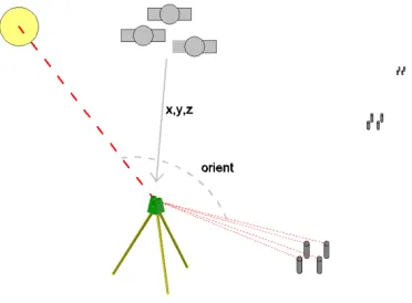
Often surveyors have to traverse long distances with a total station, sometimes over difficult terrain, only to take a small number of observations. This project hopes to reduce the need for these time consuming tasks. A number of examples have been formulated to demonstrate the potential of the outcomes of this project.
Example 1. During a rural boundary definition a surveyor needs to connect to some reference trees found at the corners of the property. The surveyor has the option to either put in two marks and take GPS observations on them, or complete a traverse around the perimeter of the property, which is often in the order of kilometres.
There is the possibility of making time savings by having the ability to set up a total station, take a differential GPS position, perform an observation to the sun as a reference object and then
measure the mark on the reference tree (Figure 1).
Example 2. During the construction of a 30km long power-line, a surveyor is required to mark out the holding down bolts for each pole. A differential GPS is not relatively accurate enough for bolts that are less that 1m apart. A possible work sequence could be:
1. Set up the total station over a GPS observed mark.
2. Take a back-sight to a mark at the previous power pole
3. Set the bolts out using the total station.
4. Return to the previous pole to retrieve the back-sight.
Significant time savings in the field could be achieved if the surveyor could (Figure 2):
1. Set the total station and take a differential GPS position for station position.
2. Take an observation to the sun as a reference object.
[image:17.612.359.545.463.600.2]3. Set the bolts out and move to the next power pole.
Figure 1 Using GPS combined with solar obseservation to reduce time when limited
observations per setup are required
Figure 2 Using GPS combined with solar observations to assist with relavtivly accurate
6 0050073010-Phillip Nixon - Project Dissertation - University of Southern Queensland 2011 Example 3. A surveyor is required to take topographic observations in heavy bush, and either had to progress very slowly with a GPS, or cut survey lines with an axe and brush-hook.
If the surveyor could set up the instrument, take a differential GPS reading, and set an azimuth from the sun, then proceed to survey topographic features around the station, then move to the next position, and repeat the process, there would be no need for cutting lines, making the survey easier and less time consuming (Figure 3).
0050073010-Phillip Nixon - Project Dissertation - University of Southern Queensland 2011 7
Chapter 2.
Literature Review
[image:19.612.114.558.188.487.2]To establish an understanding of what this dissertation achieves, it is required to make a presentation of information on the different components necessary to achieve the azimuth determination. The overview of these individual compents and the method used in the project is shown in Table 1.
8 0050073010-Phillip Nixon - Project Dissertation - University of Southern Queensland 2011 2.1 Solar Radiation
The sun generates energy in the form of electromagnetic radiation. This radiation can be detected and observed in the form of heat and light. The majority of the solar spectrum is between 280 and 2000nm, with a peak at around 550nm (Standards Australia 2003). A Leica TPS1200 total station has a magnification of 30 times; therefore this intensity is magnified down the telescope at 30 times the rate of the incoming beam (Leica Geosystems 2007). This creates a dangerous situation for operator’s eyes, and damaging heating of the internal electronics and mechanisims inside the instrument. The main damage to an instrument by pointing at the sun is to the wave filter on the EDM module (Figure 4).
2.2 Existing filter lenses and protective equipment and techniques
There are numerous pieces of existing equipment for taking safe sun observations including a dark glass, a Roelof’s prism and the Simplex Solar Shield. There are also a few field techniques for taking solar observations without the use of protection, but these should be used in secondary preference to the protective equipment (Bennet 1980). Dark Glass
[image:20.612.336.516.106.353.2]With a conventional theodolite the sun observations could be performed using a dark glass, which was attached to the eyepiece of the telescope (Figure 5). This had the effect of cancelling out the harmful rays while still letting enough light through to a take reading to the sun (Bennet 1980). Using the protective filter lens the edges of the sun are generally observed using the vertical cross hair inside the telescope.
Figure 5 Sun Dark Glass Observation Filter Lens for Wild T1A
Figure 4 EDM Module for Leica 1100 series total station
0050073010-Phillip Nixon - Project Dissertation - University of Southern Queensland 2011 9 Roelof’s Prism
Roelof’s prism is a tool used to split the sun’s image into four circles, which form a star shape when viewing the sun, and when the intersection of the circles are lined up with the crosshairs, the centre of the sun is obtained (Figure 6)(Allan et al. 1975).
Figure 6 Roelof’s prism (Hashimi 2005) (left) and view through a telescope (Hilster 2011) (right)
The Simplex Solar Sheild
The simplex solar shield, while not as common as the Roelof’s prism is also used for obtaining solar readings. Developed by Professor C.Wall in 1940, it covers the lens of the telescope with a blocking haloed X. When the sun is invisible behind the shield the centre of the sun has been obtained (Schmitt 1940).
Figure 7 Passage of the Sun across the Solar Shield (Schmitt 1940)
No Protection
The main field technique when there is no protective filter lens or shield available is as follows (Bennet 1980):
• Roughly align the sun with the “gunsight” on the top of the telescope • Set the telescope’s focus to infinity
• Project the sun’s image, through the telescope, onto a piece of paper.
• By varying the eyepiece focus, sharp images of the sun and crosshairs will be projected on the piece of paper.
10 0050073010-Phillip Nixon - Project Dissertation - University of Southern Queensland 2011 The Leica GOV13
Leica currently have a protective filter lens available for use known as the GV013. It is built by Swissoptic and fits over the objective end of the total station (Figure 9).
The main problem with modern total stations is the measuring equipment inside could be damaged by the magnification of the sun’s rays through the lenses. The GV013 and the Roelofs prism are the only type that can be fitted over the objective end of the total stations telescope (Hashimi 2005). None of these existing lenses were found to be suitable for use in this project.
0050073010-Phillip Nixon - Project Dissertation - University of Southern Queensland 2011 11 2.3 Filter & Lens Design
2.3.1 Filters
There are generally two types of optical filters, absorptive and dichroic filters. Absorptive filters work by absorbing the selected wavelength of light passing through them, transforming the light into heat. Absorptive filters are mostly constructed by making the filter medium the colour that is required to be removed. Dichroic filters stop the light waves by reflecting the light by using a series of reflective optical coatings (Figure 10) (Wikipedia Contributors 2011).
Figure 10 Absorptive Filter (left) and Dichroic Filter (right)
Dichroic filters using thin film designs to create a series of sub filter types that are used for specific purposes. These are known as edge filters and create their own subset of Dichroic filters (Paschotta 2011). These include:
Low-pass or Short-pass filters – This type blocks all wavelengths above a certain value
and allows the remaining wavelength range to pass through.
High-pass or Long-pass – This type of filter blocks all wavelengths below a certain
value and allows the remaining wavelength range to pass through.
Band-pass filter – These are generally a combination of a Low and High pass filter, and
only allow a certain wavelength range to be transmitted through.
Notch filter – This type of filter only blocks a certain wavelength range.
12 0050073010-Phillip Nixon - Project Dissertation - University of Southern Queensland 2011 2.3.2 Lens
The type of lens which would be of most use for this project is a parallel lens. Snell’s law explains the relationship between a ray of light passing from media of one density to another. It shows that the angle of light is refracted when passing through from one medium to another, but it also works in reverse, when the light is refracted out of the lens. When this is the case the beam is deflected back to its original angle, with the change in position being known as displacement. The greater the angle of incidence from perpendicular, the greater the amount of displacement, as shown in Figure 12 (Page 1943).
Parallel plate lenses have been in common use in the surveying industry. They are mostly found in parallel plate micrometers, which fit over the front of an automatic level and are used by tilting the lens plate to get a micrometer reading on the nearest graduation of the levelling staff (Allan et al. 1975).
0050073010-Phillip Nixon - Project Dissertation - University of Southern Queensland 2011 13 2.4 Leica TCRP1203+ Total Station
This project used the facilities available on the Leica TRCP1203+ Total Station. The following is an overview of the parts of this instrument that were used in this project.
2.4.1 ATR
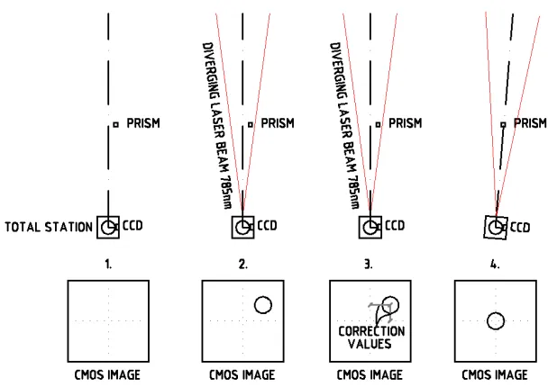
Automatic Target Recognition (ATR) is a process used by modern robotic total stations to lock on to, and correct for, angle readings to a prism. It uses a Complementary Metal Oxide Semiconductor (CMOS) sensor to take images of the prism and then uses “blob detection” algorithms to find the centre of the blob. The total station will then correct the total station direction to the centre of the prism using the onboard robotics.
Early types of automatic target recognition were performed by measuring the strength of the laser beam return and locking onto the highest strength return. These types required the target to be in a relative known position and had little tracking capabilities (Key 2008). The first commercially available total station with target recognition and tracking was the Geodimeter 4000 instrument, which was released in 1992. (Kirschner & Stempfhuber 2008).
In the Leica 1200 series total stations the ATR is performed by emitting a near Infrared Laser beam at 785nm. This laser beam is classed as a Type 1 according to IEC 60825-1 (2007-03), which makes it safe for the unprotected human eye. If the prism is in the view of the CMOS sensors’ range, which is 5 degrees, the signal will be returned as shown by step 2 in Figure 13 (Kirschner & Stempfhuber 2008).
The prism will then reflect this beam, with the return signal directed through a Dichroic beam splitter to separate the visible from infrared light; then magnified through a number of lenses; and then into then CMOS sensor. The returning image is a grey scale image, which is converted to black and white pixels (Weyman-Jones 2010).
Once the image has been captured, the centre of the returned white or reflected pixels of the image is calculated, which is the centre of the prism. This position is then compared to the centre of the image, and using pre-calculated values, rotation in gons is calculated as shown by step 3 in Figure 13.
14 0050073010-Phillip Nixon - Project Dissertation - University of Southern Queensland 2011
Figure 13 Overview of the ATR system
The Leica instruments have a number of features to speed up and reduce common errors associated with ATR. The instrument will not always point directly to the centre of the prism. As the angular values to correct to centre are known, if the telescope is within a specified tolerance of the centre of the target and an electronic distance measurement can be made, the machine will take the reading and apply the corrected angles to the recorded measurement (Weyman-Jones 2010).
In the case of sun observations this is important, as the sun is in constant movement, therefore making direct pointing and simultaneous time recordings manually difficult. If the instrument needed a stable prism the process of following the sun would not be possible.
[image:26.612.119.423.57.272.2]The other feature that is imperative to this project is the Leica 1200 total stations “emitter on/off” function (Bayoud 2006). In the case where there is more than one infrared source, for example the reflection of the sun off a car, the instrument will take an image, turn the emitter off, take another image, and use the results to identify which reflected signal is the prism (i.e. the blob that is not visible when the emitter is off, is the prism). This is then confirmed by the instruments ability to take an EDM reading to the prism (Figure 14).
0050073010-Phillip Nixon - Project Dissertation - University of Southern Queensland 2011 15
Figure 15 Telescope view (left), CMOS view emitter on (middle), CMOS view emitter off (right)
To further demonstrate this function, views through the telescope have been recorded using an infrared compatible camera, shown in Figure 15. A desk lamp was turned on to simulate another emitter of radiation, and cross hairs have been superimposed over the CMOS images (middle and right). The left view shows the reflected radiation from the prism, the middle view shows both the lamps radiation and the reflection from the prism and the right view shows the laser switched off to identify the reflected radiation. From this point the instrument aligned itself to the point where the radiation was not being reflected.
2.4.2 Horizontal Circle
Since the advent of electronic angle measurement techniques the horizontal and vertical circle have been read by a series of glass plates with either incremental or coded graduations. The angle is read by passing light through the plate and reading the binary graduation with photo diodes (McDougal 2004). The Leica TCRP1203+ has the ability to read this plate to within 3 seconds of arc in both the vertical and horizontal circle. This reading is then displayed on the screen. When taking a recorded reading the instrument will often record a measurement different to that displayed on the screen, as the ATR system performs a calculation of correction to the centre of the prism, although it is not pointing directly at the prism (Leica Geosystems 2007).
2.4.3 Clock
16 0050073010-Phillip Nixon - Project Dissertation - University of Southern Queensland 2011 2.4.4 Onboard Computer System
The Leica TRCP1203+ has on-board computing for recording and calculating measurements in the field. This software is based around a window CE operating system, and measurements are recorded onto a CF card, inserted into the side of the instrument (Leica Geosystems 2002).
0050073010-Phillip Nixon - Project Dissertation - University of Southern Queensland 2011 17 2.5 Sun observations for azimuth
2.5.1 Azimuth
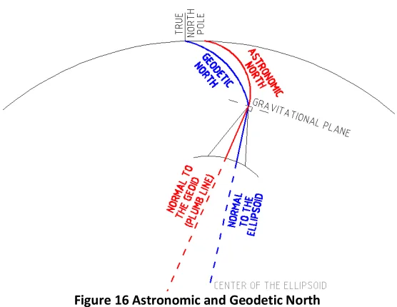
Azimuth is the horizontal angle going in a clockwise direction from the northern facing end of the local meridian (Bennet 1980). There are a few types of azimuth currently in use. A magnetic azimuth is based on the magnetic pole of the earth, and can also vary over time and from place to place depending on local conditions. The geodetic azimuth is relative to the meridian’s lines of the earth, which run from the true North Pole to the true South Pole. The astronomical azimuth is related to the geodetic azimuth, but changes from location to location, due to the gravitational effects of the earth (Hamilton 2002).
The other type of azimuth is a grid azimuth. A lot of survey work is done on a local grid, where the ellipsoidal shape of the earth is projected onto a flat plane, for example the Map Grid of Australia (MGA). This results in a convergence between true north and grid north that differs depending on how far the subject area is from the central meridian (University of Queensland 2009).
The difference between a geodetic azimuth and an astronomical azimuth is due to the deflection of the prime vertical. This method for accounting for the deflection of the vertical is known as the Laplace correction. The Laplace correction is a function of the east west slope of the geoid (Hamilton 2002). The error caused by the Laplace correction is generally small, but it can be easily programmed and if a geoid is available on the instrument for use, then it should be applied.
[image:29.612.196.474.488.703.2]Grid correction changes depending on the grid projection and how far the position is from the central meridian. Common grid projections used in Australia at the present point in time are the Integrated Survey Grid (ISG), and the Map Grid of Australia (MGA).
18 0050073010-Phillip Nixon - Project Dissertation - University of Southern Queensland 2011 2.5.2 History
There is speculation that the sun may have been used for azimuth determination for the alignment of the ancient pyramids in Egypt, using a pyramidal block and the path of the sun over the course of a day (Neugebauer 1980). In recent centuries, the determination of a precise azimuth from the sun was realised by William Austin Burt, who invented a device called the solar compass in 1836 after experiencing magnetic variation while surveying in Wisconsin. By combining the ephemeris data and settings on the solar compass, true north could be set using the attached telescope or sights (Dunham et al. 2006).
2.5.3 Methods
There are currently two commonly used ways of obtaining an azimuth from a celestial object, the sun or stars, the “Azimuth Altitude method” and the “Hour Angle method” also known as the “Time Azimuth method”. Both methods require the operator to know the latitude and longitude of a station to within one second of arc.
0050073010-Phillip Nixon - Project Dissertation - University of Southern Queensland 2011 19 The Azimuth Altitude method
This method uses a vertical circle reading combined with a horizontal angle reading. This method also requires either a barometric pressure reading or height determination. Accuracies of around one minute of arc are relatively typical of this type of observation method (Hamilton 2002). The azimuth altitude method, although easier to calculate and having a reduced reliance on the time keeping, also has a number of systematic errors that need to be taken into account.
These errors include:
1. Vertical circle – as a vertical circle reading needs to be taken, the operator must ensure that the vertical circle correction is applied, the trunnion axis is in good order (or values accounted for), and the alignment of the horizontal and vertical circle is perpendicular and eccentricity free. Many of these errors are adjusted out in a normal traverse, due to reverse heighting, but as the angle will not be measured back from the sun, these values must be known (Bennet 1980).
20 0050073010-Phillip Nixon - Project Dissertation - University of Southern Queensland 2011 The Hour Angle Method
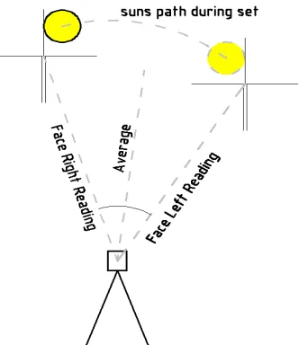
Also known as the Time Azimuth method, this process involves reading the horizontal angle to the sun and taking a highly accurate time reading. The commonly used method for taking a sighting to the sun is to use opposing sides of the sun in the left and right face, sighting the vertical cross hair of the telescope. By taking the average of these readings the centre of the sun is obtained. The average time will also be taken which is used for right ascension, Greenwich Hour Angle (GHA) and declination calculations.
The process of taking and calculating solar observations using the hour angle method is as follows:
1. Take a reading or readings in face left and face right to a reference object and the sun, while taking accurate time readings.
2. Take the average of the sets and time readings and apply time zone corrections to obtain the UTC time.
3. Apply the DUT1 (leap second) correction.
4. Obtain and calculate the Greenwich Hour Angle (GHA) for the time of observation and the station coordinates from ephemeris (this can also be calculated using Craymer’s 1984 formula).
5. Add the longitude of the station to the GHA to get the Local Hour Angle (LHA). 6. Use the LHA to get the value for t. Before noon this is 360° - LHA, and after noon
this is the LHA.
7. Obtain and calculate the declination of the sun from ephemeris (δ) (this can also be directly calculated using Craymers 1984 formula).
8. Use this to find the declination at the time of observation.
9. Using the values of latitude (θ), t and local declination (δ) find the azimuth of the sun.
10.Use this azimuth to calculate a correction to the horizontal angle and therefore the correction to the backsight.
11.Calculate Laplace correction from Latitude and Longitude coordinates and Geoid file and apply.
[image:32.612.333.499.86.278.2]12.Calculate and apply true to grid conversion if necessary. (Modified from Hashimi (2005))
0050073010-Phillip Nixon - Project Dissertation - University of Southern Queensland 2011 21 2.5.4 Errors associated with solar observations
Instrument Dislevelment
An advantage of using modern total stations is the dual axis compensators that correct for horizontal and vertical circle dislevelment. This dislevelment is one of the most significant errors in taking solar or astronomic observations, and in the past was corrected by taking a reading of the dislevelment of the alidade bubble and applying a correction. With the compensators, this correction has already been applied, and is measured more accurately than could be performed by the operator (Hashimi 2005).
It was partly due to this dislevelment error that observations for azimuth were recommended to be taken at less than 45°, or close to the horizon. The other reason for the
recommendation that the
observations be taken at less than 45° and not within 2 hours of apparent noon, is at this time the sun has the greatest amount of movement across the sky, as can be seen on the Figure 19 for a typical summer day at Port Macquarie, Australia. It can be seen that between 10am and 2pm local time the sun is moving at a rate of approximately 38” in azimuth per second of time.
Time Recording
There are many methods of acquiring time, for use in Hour Angle calculations. Previous to the introduction of the telegraph worldwide, time observations we completed using noon observations, using a transit telescope. Around the 1890’s the telegraph was being used to take time corrections. After that the introduction of time signal transmissions broadcast (McDiarmid 1914) on shortwave and medium wave radio signals meant time readings could be taken using the 6 ‘pip’ broadcast (Bennet 1980).
Most modern total stations, due to the onboard computing systems have some ability to record time, and provided these are correlated to UTC, should be sufficient for taking sun observations (Hashimi 2005).
22 0050073010-Phillip Nixon - Project Dissertation - University of Southern Queensland 2011 Pointing Errors
Using the Hour Angle method, less emphasis is put on reading to both cross hairs, therefore pointing errors are reduced. Also refraction and vertical circle errors are reduced using this method (Bennet 1980). The errors derived from latitude changes and seasonal changes are also reduced. Using this method means there is no need to correct for parallax and refraction (Hashimi 2005).
The combination of time and pointing errors leave two significant human errors that need to be accounted for, when using a modern total station to take solar observations. Reliance is still placed on the operator to line the sun up with the cross-hairs and press the button to record the observation, either on a stopwatch or on the instrument itself.
2.5.5 Time
The time required for making Hour Angle observations is the astronomical time scale referred to as ephemeris time (ET). ET was developed and implemented in 1952 and is a measured from the first of January 1900, with the unit of time “second” being based on the length of this year. This equated to 1/31556925.975 of a year (Guinot & Seidelmann 1988). Due to the second length changes introduced by atomic clock and the gradual slowing of the earth’s rotation, ET is out of currently out sync with Coordinated Universal Time by 66.32 seconds.
Coordinated Universal Time (UTC) is a timescale based around the average rotation of the earth, and is referenced by the mean solar time at the Greenwich meridian. This is the time that is broadcast by shortwave radios. UTC is periodically corrected either on the 1st of January or September when it is out of synchronization by more than 0.5 of a second. These corrected seconds are known as leap seconds and account for the gradual slowing of the earth and other changes in the earth’s rotation.
UT1 is the exact average rotation of the earth, and is referenced by the mean solar time at the Greenwich meridian. The correction between UTC and UT1 is referred to as DUT, which is the leap second correction. Currently these times are measured using Very Long Baseline interferometery, which uses a series of telescopes around the world to make simultaneous observations to the same celestial object.
0050073010-Phillip Nixon - Project Dissertation - University of Southern Queensland 2011 23
Figure 20 Time differences from UTC from 1980-2011
The National Marine Electronics Association (NMEA) string exporting is available on most GPS receivers, whether they are small hand held devices or Differential GPS receivers (Lambrou & Pantazis 2008). The Leica ATX1230 GPS system records time in UTC, and has the ability to export a NMEA string, which can be used for timing. If GPS observations are being taken to establish position, time could also be measured at this point.
2.5.6 Prediction of Right Ascension and Declination
Conventionally right ascension and declination are calculated using prediction tables, for example a star almanac or catalogue. These types of tables are based on a system when handheld calculators or microcomputers were not available for common use, and were associated with trigonometric or logarithmic tables. The process of getting a value involved finding the two closest values to the subject time and interpolating a result by a ratio of the time change (Hashimi 1985).
Since the introduction of programmable calculators and micro-computers, the extensive formula required to calculate these values has allowed algorithms to be written specifically for calculators and micro-computers. These programs can calculate the required value to fractions of a second (Hashimi 1985).
Since the late 1970’s there have been a number of different methods for calculating the sun’s position at any time of the day, mainly with sections extracted from Jean Meeus’ book Astronomical Algorithms released in 1979.
In 1980 Bennet published in “The Australian Surveyor” an article outlining the basic formula to calculate right ascension, GHA and declination, for any time between 1980 and 2000. Bennet explains in his article that the algorithm was accurate for the these two
-70 -60 -50 -40 -30 -20 -10 0 10
1
/0
1
/1
9
8
0
1
/0
5
/1
9
8
1
1
/0
9
/1
9
8
2
1
/0
1
/1
9
8
4
1
/0
5
/1
9
8
5
1
/0
9
/1
9
8
6
1
/0
1
/1
9
8
8
1
/0
5
/1
9
8
9
1
/0
9
/1
9
9
0
1
/0
1
/1
9
9
2
1
/0
5
/1
9
9
3
1
/0
9
/1
9
9
4
1
/0
1
/1
9
9
6
1
/0
5
/1
9
9
7
1
/0
9
/1
9
9
8
1
/0
1
/2
0
0
0
1
/0
5
/2
0
0
1
1
/0
9
/2
0
0
2
1
/0
1
/2
0
0
4
1
/0
5
/2
0
0
5
1
/0
9
/2
0
0
6
1
/0
1
/2
0
0
8
1
/0
5
/2
0
0
9
1
/0
9
/2
0
1
0
D
if
fe
re
n
ce
f
ro
m
U
T
C
i
n
s
e
co
n
d
s
24 0050073010-Phillip Nixon - Project Dissertation - University of Southern Queensland 2011 decades due to the difference between ephemeris time (ET) and universal time (UTC) which in 1980 was 50 seconds, and he predicted would be 1 minute in 1990. The value for this difference in 2010 is now 66.32 seconds (Schlyter 2011).
0050073010-Phillip Nixon - Project Dissertation - University of Southern Queensland 2011 25 2.5.7 Effects on ephemeris calculations
The effects that affect right ascension and declination of the sun as follows:
1. The effect of Procession – this is the motion of the equinoxes, which is attributed mostly to the gravitational forces of the sun and moon on bulge of the earth at the equator (Hashimi 1985).
2. The effect of Nutation – this is the change in the position of solar bodies due to the gravitational effect of the sun and moon on the earth, and the change in distance between them (Hashimi 1985).
3. The effect of Annual Aberration – this is the effect caused by the apparent displacement of a solar body due to the movement of the earth on its orbit (annual aberration), and rotation about its axis (diurnal aberration) (Hashimi 1985).
4. The effect of proper motion – this is the motion of a solar body with relation to earth (Craymer 1984b).
26 0050073010-Phillip Nixon - Project Dissertation - University of Southern Queensland 2011 2.6 Accuracy of using sun observations
Using the previously mentioned algorithms, the azimuth of the sun can be calculated at any time without tables to approximately 1”. The Leica TCRP1203+ has an angular standard of 3”, and the 780BP20 bandpass filter has a parallelism error of 25”.
After doing testing over several baseline locations in the Philippines, Dimal and Balicanta (2009) found that they could get solar observed azimuths to agree with GPS co-ordinates with a maximum error of 40”. They also found that the length had no discernable effect on the precision of the azimuths, with their testing done over a range of distances from 100 to 300m (Dimal & Balicanta 2009). They came to the conclusion that tertiary, and in some cases primary control, could be established by using solar observations.
Lambrou and Pantazis 2008 used a total station with Roelof’s prism attachment with a GPS system attached for time recordings, and found that they could get very accurate results in instruments, when measuring 15 sets to Polaris in the Northern Hemisphere. Using manual pointing and recording techniques, they achieved standard deviations of 2”using a 3” instrument. It does not appear that they checked the derived azimuth with any published values for their experimental position.
0050073010-Phillip Nixon - Project Dissertation - University of Southern Queensland 2011 27
Chapter 3.
Methodology
For this project a number of tests were performed: 1. Checking the ATR read and locked onto the sun.
2. Which filter lens was best for locking on to the sun using ATR, and what results are obtainable using different filter lens types.
3. What is the accuracy obtainable using the ATR tracking of the sun: -During different times of the day.
-Using different station establishment techniques (known mark, RTK GPS on backsight, using RTK GPS on both marks).
3.1 Protection of equipment and safety of personnel
Looking at the sun through any telescopic instrument can be dangerous to personnel if
proper precautions are not adhered to. Do not point the telescope at the sun without
protection on the front of the telescope as it will damage your eye and the instruments
electronics. The sun’s intensity is magnified by the magnification rate of the telescope.
3.2 Lens and Filter Selection Tests
Experimentation on a series of filter lenses for protecting the instrument and personnel, while still allowing ATR readings, were performed. Various methods of testing were used on each filter lens, with a positive result in one test, leading to a test of the next method. Heating caused by magnified radiation – To
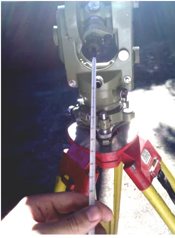
assess the possible heating that was going to occur due to the direct pointing to the sun, a Wild T1A theodolite was used, with the filter lenses mounted over the objective end, and the temperature measured at the point of convection approximately 5mm from the observing end of the telescope (Figure 21).
[image:39.612.386.563.415.656.2]ATR stops search when sun came into view – The filter lens was placed over the objective end of the total stations telescope. The telescope was then pointed roughly at the sun and a spiral search was initiated. When the sun came into the range of the ATR’s view, it was recorded whether or not the instrument would stop to perform an emitter on/off check.
28 0050073010-Phillip Nixon - Project Dissertation - University of Southern Queensland 2011 ATR search lock to sun- The filter lens was placed over the objective end of the total station’s telescope. The telescope was then pointed roughly at the sun and then by pressing the distance button the total station would do a spiral search, looking for the “prism”. It was recorded whether or not the instrument would lock onto the sun when doing a spiral search.
Direct pointing – The filter lens was placed over the objective end of the telescope. The total station was then placed in “lock” mode and the telescope was pointed directly at the centre of the sun.
0050073010-Phillip Nixon - Project Dissertation - University of Southern Queensland 2011 29 3.3 Test Filter Lenses
Welding lens
A Shade 10 welding lens was purchased from a local hardware store for $AU12. According to AS1338.1 it is an absorption filter, and allows small percentages (0.0003-0.6%) of the entire spectrum to be transmitted. (Standards Australia 1992)
The inside of a floppy disc
On a hint from an internet forum on camera photography (DIY Photography 2007) the inside of a 5 ½ inch floppy disk was placed over the objective end of the telescope. The cost of this filter lens was approx $AU0.10 cents.
Commercial Infrared Camera Protective Filter Lens
Purchased online for around $AU40, the protective filter lens blocks out all visible light up to 550nm
785BP20 bandpass filter
This filter lens blocks all light outside 775 to 795nm and was bought online for around $AU30. The filter lens has a specified error of parallelism of 5-25”.
Leica GV013 protective lens
30 0050073010-Phillip Nixon - Project Dissertation - University of Southern Queensland 2011 3.4 Refraction Testing
As many of these filter lenses are not built with a high degree of precision a test was devised to measure the accuracy of the lens, as well as the ramifications of not having the lens mounted exactly parallel to the instrument.
To achieve this a Leica Circular prism of 50mm in diameter was set in an enclosed testing range, at a distance of 33m. To eliminate booking and human errors, observations were taken using the ATR and recorded automatically by the instrument using the “sets of angles” program. The Leica TRCP1203+ has a pointing accuracy of 3”, and to increase the accuracy and reduce the chance of outliers, 8 sets were observed in both faces increasing the potential accuracy of the instrument to 1.06”.
At this range, every minute of deflection is equal to 10mm. The 780BP20 is 5.77mm thick with a parallelism error of 5-25”.
Width: 5.77mm
Max angle of parallelism: 25”
Refractive Index: 1.52 (assumed crown glass) Maximum twisting of lens in housing 5°
3.4.1 Maximum Deviation due to Parallelism
sin sinr ag
arcsin sini ga i
arcsin sin25"1.521 25"
38" 25" 13" Where
x=angle of deviation
i=error in Parallelism and angle of incidence
r=refracted angle
0050073010-Phillip Nixon - Project Dissertation - University of Southern Queensland 2011 31 3.4.2 Maximum deviation due to lens housing twist
cos sin1
arcsin sin g
1
cos arcsin sin g sinarcsin
sin g
5.77 1
cos arcsin sin5 1.521 sinarcsin
sin5 1.52
1
0.757
Where
i= angle of incidence r=refracted angle
g=refractive index (glass=1.52) a= refractive index (air =1) d=displacement
t=lens width
Over 33m deviation cause by 0.757mm displacement atan 300000.757
4.7"
32 0050073010-Phillip Nixon - Project Dissertation - University of Southern Queensland 2011 3.5 Automatic Target Recognition
The main objective of this project was to test the effectiveness of using the ATR on the modern total station to track the sun’s movement, which in the field could use a search function, to find the sun in a section of the sky, without the operator having to observe through the telescope. This would negate the pointing error associated with solar observations.
To the total station the sun should look very similar to a standard circular prism. The only property in which the sun differs from a prism is that the sun is an emitter of radiation, not a reflector. The Leica 1200 series total stations have in the ATR function, an emitter on/off function, where the instrument checks to make sure the prism is a reflector, by turning off the emitted laser, and checking for reflection.
As a result of the emitter on/off function, the total station would stop when the sun came into view, showing that sun had been found by the CMOS sensor, but would continue its search after doing an emitter on/off routine. The author recommends that due to the success of this project, manufacturers might be able to add a function to their total stations that allows the instrument to be used with the emitter on/off function disabled. Using the 785BP20 bandpass filter mounted over the objective end of a Leica TCRP1203+ total station a reading was able to be obtained by using the following method (see section 4.1) :
1. Put the instrument into lock and Low Visibility mode.
2. Put the instrument into search mode by pointing it at a prism and then twisting it away, initiating the search mode.
3. Point the instrument at the sun.
4. Hold a prism close to the instrument until it obtains “lock” and then remove it quickly.
5. The instrument will then track the sun until the instrument does an emitter on/off check. This is normally around 1-1.5 seconds.
6. Take the reading during this time.
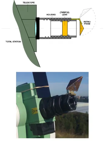
0050073010-Phillip Nixon - Project Dissertation - University of Southern Queensland 2011 33 To facilitate the ease of this process a small retro prism was mounted on at hinge on the end of a lens housing. The filter lens was mounted inside a detachable front section that can be removed to facilitate normal total station functions. This device is known as Nixon’s Solar Observations Device (NSOD) (Figure 23). A welding lens was also attached to the front of the telescope above the aperture to assist with rough pointing of the instrument at the sun. It was found that the “gunsight” crosshairs mounted on the top of the telescope were still clearly visible with the welding lens in place.
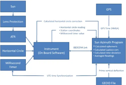
34 0050073010-Phillip Nixon - Project Dissertation - University of Southern Queensland 2011 3.6 Solar observation method
To obtain an azimuth the Hour Angle method was used. This involves taking horizontal angles to the centre of the sun in both faces. This differs from conventional methods, which use the opposing edges of the sun in opposing faces. This negated the need for semi-diameter corrections to correct the angle to the centre of the sun.
The calculations for the observation method were calculated using the Visual BASIC program. The steps in the program are as follows
1. Before starting observations a GPS base time and instrument millisecond timer recording are taken.
2. The station values are taken from the instrument and converted to geodetic coordinates and a grid correction is calculated.
3. The prime vertical deflection is calculated and applied to obtain the Laplace correction and astronomic coordinates.
4. The sun is tracked by the instrument
5. Angular and time values are taken from the instrument.
6. The time from the instrument is correlated to the base time and a observations time is calculated.
7. The azimuth to the sun is calculated using astronomic coordinates and time. During this stage the Ephermis time correction is added to the time value. 8. The grid and Laplace correction are applied to this azimuth.
9. The azimuth is compared to the horizontal angle and a horizontal circle correction is calculated.
10.Steps 4 to 9 are repeated with the instrument in both faces.
11.With each extra reading an average horizontal circle correction is calculated for both faces and total. Variations are also calculated and compared to a rejection criteria of two standard deviations. Readings outside this range are flagged. 12.When the operator is satisfied with the number of observations and results, the
0050073010-Phillip Nixon - Project Dissertation - University of Southern Queensland 2011 35 3.7 Ephemeris calculations
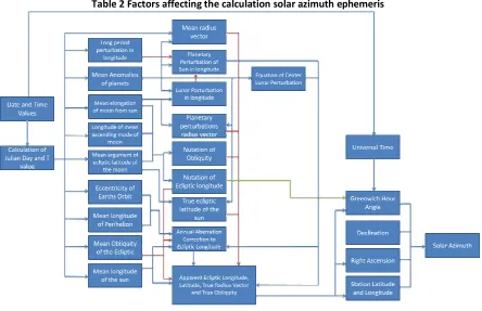
[image:47.612.115.559.193.480.2]The ephemeris in the past has been obtained by sun tables or a solar almanac. For this project, the ephemeris will be calculated using a slightly modified version of Craymers solar ephemeris algorithm. The formula used for this project is based on Craymer’s 1984 Fortran program transferred into the BASIC Programming Language format. It can be found in Appendix C, in the SunAz.main.frm module under the function Sun_Az. A flowchart of the process is shown in Table 2.
Table 2 Factors affecting the calculation solar azimuth ephemeris
3.8 Correction to grid
The correction to grid, in this case, is a correction from true north the MGA north. This is not really necessary to get results from the baseline, but has been added to the project, as it is not often that an ordinary land surveyor would require a true north azimuth.
36 0050073010-Phillip Nixon - Project Dissertation - University of Southern Queensland 2011 3.9 Time reading
The time reading was acquired by using a USB mounted GPS reading device, purchased for around $AU20 (Figure 24). This supplied an NMEA string, allowing the acquisition of UTC time. This time was combined with an accurate reading to the 1/1000th of a second from the instruments onboard clock. By recording a base time of both the GPS and millisecond timers the observation time was acquired by application of the millisecond change to the base time.
0050073010-Phillip Nixon - Project Dissertation - University of Southern Queensland 2011 37 3.10 Checking results
One of the proposed outcomes for the results of this project is to have a software program that will calculate an azimuth, for use when setting up over known marks on already established control, or using a Real Time Kinematic (RTK) GPS position. This is proposed for use doing small survey projects where many setups are required.
Due to this type of application, a minimum amount of observations needed to be used to get obtain a result was assessed. The accuracy testing will look at the results from 1, 2, 4 and 12 sets of observations.
To ensure that the accuracy of the technique is consistent, testing was required to be performed over the course of a day, from an area that had reliable views of the sky, as well as being able to be the connected to an existing geodetic network.
An elevated area for observing solar observations, known as the Silverwater Marker, was located in the suburb of Olympic Park. A closed traverse was performed between a mark put in at the top of the mound (Nixon’s Spike) and state survey marks SSM26830, SSM99411, and SSM99412. These all have satisfactory values in MGA (Figure 25). The traverse used 9 sets of observations at each station to reduce the angular accuracy of the instrument to 1”. The traverse had a 1” angular misclosure, which was adjusted out using a Bowditch adjustment.