1 INTRODUCTION
For the past decade, fibre reinforced polymer (FRP) composites have found increasingly wide applica-tions in civil engineering, both in retrofit of existing structures and in new construction. FRPs offer ad-vantages compared to traditional construction mate-rials for being lightweight, high strength and corro-sion resistant. As a result, application of composite piles started to gain acceptance in pile rehabilitation and replacement. Indeed, several studies around the world are currently underway examining its beha-viour and its extent of relevance in waterfront and highway structures.
Pile materials such as steel, concrete and timber have limited service life when used in harsh marine environment due to corrosion, degradation and ma-rine borer attack. These problems coupled to tradi-tional materials led researchers to investigate the feasibility of adopting FRP composite piles as an al-ternative in piling system. Review of the available li-terature shows that currently there are five common types of composite piles which are considered as po-tential substitutes. These include plastic encased steel pipe core piles, structurally reinforced plastic matrix piles, concrete-filled FRP tubular piles, fiber-glass pultruded piles and plastic lumber piles (Ni-roumand, 2009). Among these five pile types, the first three are considered to be better suited for load– bearing applications (Lampo et al., 1998). Concrete-filled FRP piles, which somehow have a relation to
the present study, may be made from filament winding, pultrusion, and resin transfer molding processes (Iskander & Hassan, 1998). The FRP shell provides, among other things, a stay-in-place con-crete form, confinement to the concon-crete, tensile rein-forcement, and corrosion protection (Fam & Rizkal-la, 2001) while the concrete infill provides compressive load capacity.
Basic among the in-need for assessment in FRP composite piles is its behaviour when subjected to axial compression. The response of the pile under axial loading is considered to be among the factors that most affect the superstructure’s behaviour espe-cially for gravity loading (Comodromos et al., 2009), thus this necessitates attention.
Studies on hollow FRP composite piles are very rare due mainly to some issues particularly on its performance when driven on the ground. Mirmiran (2002) found out that empty tubes are susceptible to buckling and damage during driving due to lower impedance and can only sustain driving stresses up to 40-50% of the refusal rate of the concrete piles, unless driven to shallow depths or in soft soils. However, this driving issue is not considered as sig-nificant if hollow FRP composite piles are used in partial replacement of a damaged traditional pile where driving force is not required. Outcome of the previous study conducted by Pan-do et. al. (2002) on concrete-filled tubular pile re-vealed that both of the components responded signif-icantly until failure with unique responses at
Behaviour of fibre composite pile under axial compression load
E.J. Guades, C.S. Sirimanna, T. Aravinthan & M.M. Islam
Centre of Excellence in Engineered Fibre Composites (CEEFC), Faculty of Engineering and Surveying, University of Southern Queensland, Toowoomba, Queensland, Australia
different stress levels. At the maximum stress level, concrete core started to experience apparent micro-cracking while FRP shell applies a radial confining pressure increasingly due to its elastic properties. It was concluded from this study that ultimate peak strength of the composite pile was mainly governed by the hoop tension of the FRP shell.
FRP tube behaviour was investigated by Hashem and Yuan (2000) using experiment and numerical analysis. Result showed that the compressive stress-strain relations for all specimens were largely linear. Initiation of failure in these segments occurred at the bottom surface of the specimen. The complete col-lapse happened after micro-buckling leading to the delamination of all four laminates making up the cross section and the virtual crushing of the bottom surface of the specimen.
This paper experimentally and numerically in-vestigates the behaviour of hollow FRP composite pile under axial compression. Both results are pre-sented to compare its behaviour derived from expe-riment and FE analysis.
2 EXPERIMENTAL PROGRAM
Test on short FRP pile was conducted to determine its behaviour under axial compression load prior to laminate test. FRP pile was loaded up to a maximum load of 414 kN. Detail of this experiment is later considered and discussed in this section. Discussions include pile material properties, laminate lay-up and test methodology.
2.1 Materials and pile laminate layup
Two basic lamina materials were used in the expe-riment and in finite element analysis namely; 0.5 mm thick lamina reinforced by 601 (600 gsm) biaxi-al [0/+90] fiberglass with vinyl ester and 2.0 mm thick lamina reinforced by Soric XF with vinyl es-ter. The geometric properties and laminate lay-up of the FRP composite tube are presented in Tables 1 and 2, respectively.
2.2 Test methodology
To characterise the behaviour of both laminate and FRP tube, two basic types of tests were undertaken in this study. Laminate testing was done to deter-mine the material properties of the laminate material and compression test was performed on short FRP composite pile to evaluate its behaviour under axial compression load excluding the effect of buckling. Laminate test was undertaken in this study to de-termine the material properties of a 22mm thick la-minate (i.e. combined effect of fiberglass and Soric XF reinforced laminae). Four test coupons taken di-rectly from the composite tube were tested according
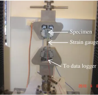
to ISO14126:1999- Plastic Compression Test. To monitor the deformation, two strain gauges were po-sitioned on the mid-height of the specimen. Collec-tions and recordings of data were generated using Systems 5000 data logger connected to the upper load cell and strain gauges. Figure 1 shows the set-up and instrumentation of the laminate test.
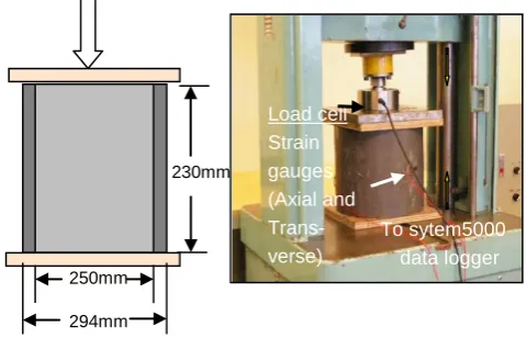
Compression test on short pile was conducted us-ing a 500 kN loadus-ing capacity AVERY testus-ing ma-chine. Test set up was arranged as shown in Figure 2 including indicated pile dimensions. To protect pile circumference edges from compressive crushing, a piece of plywood was placed on both ends of the specimen. The specimen was loaded up to a maxi-mum load of 414 kN at a rate of 2 mm per second. Four unidirectional strain gauges were positioned at the mid-height of the specimen. Collections and re-cordings of data were generated using Systems 5000 data logger connected to the upper load cell and strain gauges.
Table 1. Geometric properties of FRP tube.
Properties Property value Unit
Thickness 22 mm
Outside diameter 294 mm
Inside diameter 250 mm Height 230 mm
Table 2. Laminate lay-up and stacking of FRP tube.
Stacking sequence No. of layers
[G*/G/G/G/S/S/G/S/S/
G/S/G/S**/G/G/G/G/G 26 /G/G/G/G/G/G/G/G***]
Note: * = Ply 1, ** = Ply 13, *** = Ply 26
G = glass-reinforced lamina S = Soric XF-reinforced lamina
Figure 1. Laminate test set-up and instrumentation.
1 26
Strain gauge Specimen
[image:2.595.307.559.334.421.2] [image:2.595.307.561.468.545.2] [image:2.595.350.522.609.775.2]3 EXPERIMENTAL RESULTS AND DISCUSSION
Table 3 shows the summarized result derived from the laminate test. It should be noted that values given are average values at failure. As illustrated in the ta-ble, the compressive strength of the laminate is 87.50 MPa while the strain at failure is 0.00612. Concurrently, the compressive strength of the lami-nate can be considered as predicted strength of the composite pile assuming no buckling will take place. Apparently, load beyond this value will initiate com-pression failure on the pile.
Figure 3 shows the applied axial load - axial and lateral strain behavior at the mid-height of the 230 mm FRP tube. The axial and lateral strain of the composite pile under 414 kN (22.02 MPa equivalent stress) applied load are 1,523 microns and 452 mi-crons, respectively. The compressive modulus of FRP composite pile using linear regression is esti-mated to be 14,270 MPa. This value is comparable to the compressive modulus (14,300 MPa) derived from laminate test. Based from this result, the ap-plied load (i.e. 22.02 MPa) is only 25% of the com-posite pile’s predicted compressive capacity (i.e. 87.50 MPa). Therefore, compressive failure is not expected to occur at this loading stage.
4 FINITE ELEMENT ANALYSIS
To simulate the behavior of the short and hollow FRP pile, linear finite element analysis was em-ployed using the general-purpose FE software pack-age Strand 7. The objective of using FE analysis in this study is to determine its viability in predicting the behaviour of the FRP composite pile based on the material properties derived from tests and pro-vided data.
4.1 Mesh model
All FE models were generated using a 4-node shell element. The mesh model comprised of 1280 nodes and 1200 shell elements with a uniform mesh of 11mm x 15mm. In this modeling, laminate proper-ties were adopted as property attributes of shell ele-ments. To do this, lamina stacks made of the compo-site pile’s two component materials (i.e. fibreglass and Soric XF-reinforced laminae) were modeled. Assigned property values of each lamina where tak-en from the previous coupon tests and provided data. It should be noted that the mass of each lamina has a small effect on stress formation compared to the ap-plied load and therefore is neglected in this study. Table 4 shows the property values adopted in the FE analysis.
Figure 2. Compression test set-up on short pile.
Figure 3. Applied load-strain curve.
Table 3. Material properties of laminate at failure.
Properties Property value Unit
Compressive stress 87.50 MPa
Axial deformation 3.46 mm Axial strain 0.00612 - Compressive modulus 14,300 MPa
4.2 Boundary and load conditions
In the conducted experiment, the composite pile was in contact with stiff loading plates at the two ends. Even if the support condition may emerge to be close to a simply-supported condition, previous re-search conducted showed a much closer value to the experiment results if a “clamped support condition” is adopted (Teng and Hu, 2006). Therefore, the clamped-end condition is more appropriate for this model. To adopt such support condition, the two ends were fully fixed in all direction except that the axial displacement of the top end was left unre-strained to allow the application of axial loading. In order to properly simulate the loading condition on the specimen as described in Figure 2, vertical uniformly distributed pressure on the top of the
0 100 200 300 400 500
-1000 -500 0 500 1000 1500 2000
Lateral Strain (μ) Axial Strain (μ)
A
p
p
li
e
d
L
o
a
d
(
k
N
)
Load cell Strain gauges (Axial and Trans-verse)
To sytem5000 data logger
230mm
[image:3.595.315.555.44.198.2] [image:3.595.312.559.246.406.2] [image:3.595.307.560.477.564.2]model was applied. A 22.02 MPa uniform distri-buted pressure load was applied on the top face of the model. This applied load was identical to that of the load used in experiment (414 kN) to predict the composite pile’s behaviour under axial compression.
5 FEM RESULTS AND DISCUSSION
Figure 4 demonstrates the finite element model and deformed mode of the hollow FRP pile generated from the analysis. It is evident from the figure that both support ends of the pile undergone response from the applied load. To visibly compare the stress distribution between the top support face going to the bottom support, displacement scale was modified such that a clear deformation at the mid-height is no-ticed. The difference of the stress distribution in all regions using finite element method is diminutive so that the strain is almost constant at the ends and at the mid-height of the composite piles in axial direc-tion.
Table 5 summarizes the stress, load and strain re-sults at the mid-height section of the FRP composite pile under a maximum applied load of 22.02 MPa (414 kN). It is noticeable that values in axial direc-tion vary along its thickness with this type of lami-nate lay-up. To better understand the behaviour of the composite pile, values of plies were analysed and are shown in Figures 5 and 6.
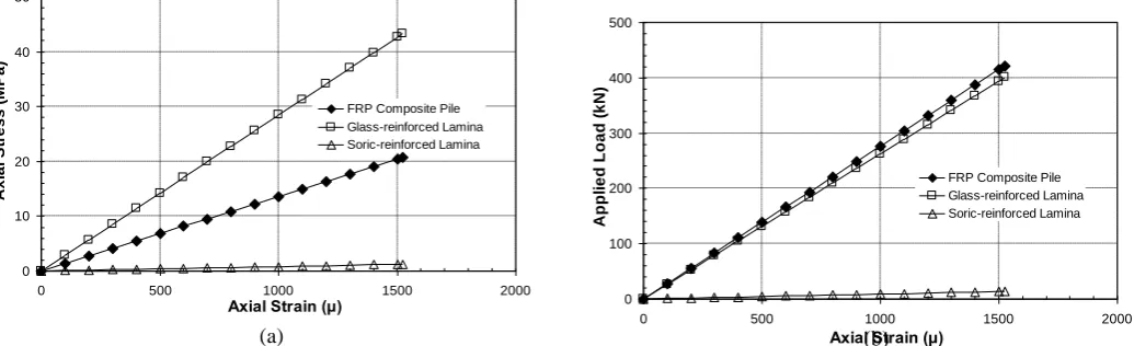
Figure 5 gives detail on the axial stress and the applied load distribution between the FRP composite pile and the main component materials at the mid-height. The adopted values of the component
mate-rials were referred from its individual average stress,
Table 4. Material properties of lamina used in FE analysis.
Property value
Properties Notation G S Unit
Elastic Modulus
11
E 28,500 800 MPa
22
E 28,500 800 MPa Poisson’s ratio
12
0.20 0.30 -
21
0.20 0.30 - Shear Modulus
11
G 11,875 307.69 MPa
22
G 11,875 307.69 MPa
Note:
G = glass-reinforced lamina S = Soric XF-reinforced lamina
Figure 4. (a) Finite element model (b) deformed mode.
load and strain values. Axial stress of the FRP com-posite pile remains intermediate as individual strain increases under this loading condition as shown in
b a
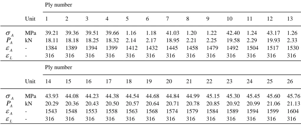
Unit 1 2 3 4 5 6 7 8 9 10 11 12 13
A
MPa 39.21 39.36 39.51 39.66 1.16 1.18 41.03 1.20 1.22 42.40 1.24 43.17 1.26
A
P kN 18.11 18.18 18.25 18.32 2.14 2.17 18.95 2.21 2.25 19.58 2.29 19.93 2.33
A
- 1384 1389 1394 1399 1412 1432 1445 1458 1479 1492 1504 1517 1530
L
- 316 316 316 316 316 316 316 316 316 316 316 316 316
Unit 14 15 16 17 18 19 20 21 22 23 24 25 26
A
MPa 43.93 44.08 44.23 44.38 44.54 44.68 44.84 44.99 45.15 45.30 45.45 45.60 45.76
A
P kN 20.29 20.36 20.43 20.50 20.57 20.64 20.71 20.78 20.85 20.92 20.99 21.06 21.13
A
- 1543 1548 1553 1558 1563 1568 1574 1579 1584 1589 1594 1599 1604
L
- 316 316 316 316 316 316 316 316 316 316 316 316 316
Table 5. Summarized stress, load & strain results of the plies at the mid-height of the pile.
A = axial stress, PA = axial load, A&L= micro-strain in axial and lateral directions, respectively. Ply number
[image:4.595.305.559.81.439.2] [image:4.595.36.547.467.680.2]Figure 5a. Based from Figure 5b, it was found that glass-reinforced lamina carries 96% of the applied load compared to that of the Soric XF-reinforced lamina. It can be ascertain from the result that former component material bears most of the load. Moreo-ver, it can be inferred that the total behaviour of the FRP composite pile under axial compression with this kind of laminate lay-up depends solely on the response of glass-reinforced lamina and the effect of Soric XF-reinforced lamina is very minimal.
The relationship of the applied load to the strain of selected representative plies on the mid-height of the model for both axial and lateral direction is given in Figure 6. For clarity, section of the tube at the mid-height is reflected indicating the labeling number of the plies (i.e. ply 1 and ply 26 at the most inner and
0 10 20 30 40 50
0 500 1000 1500 2000
Axial Strain (μ)
A x ia l S tr e s s ( M P a )
FRP Composite Pile Glass-reinforced Lamina Soric-reinforced Lamina
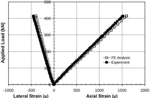
6 COMPARISON OF RESULTS
This chapter compares the results obtained from the experiment and FE analysis. Specifically, focus is on the graphical comparison of the applied load-strain
relation of the composite tube’s behaviour under axial compression.
The applied load-strain relation of the experiment outer face of the tube, respectively). It can be ob-served from the graphs that plies at this section be-have differently in axial direction but not laterally if strained under axial compression. From Figure 6a, strain variations of the plies on the axial direction were developed. The strain variations indicate that at increasing load magnitude, section at the mid-height starts to undergo wall buckling, although this premature deformation will not cause local failure or sudden collapse to the FRP composite pile as dis-cussed earlier. On the other hand, lateral strain of the plies remains the same across the thickness (i.e. ply 1, ply 2 … ply 26) of the tube irrespective of the loading magnitude as shown in Figure 6b.
and FE analysis results is exposed in Figure 7. Ap-parently, the calculated value from the finite element analysis is at par to the experimental value. The use of FE method, thus, proved to be effective in
deter-0 100 200 300 400 500
0 500 1000 1500 2000
Axial Strain (μ)
A p p li e d L o a d ( k N )
FRP Composite Pile Glass-reinforced Lamina Soric-reinforced Lamina
(a) (b)
Figure 5. Mid-height axial strain of FRP pile and its component materials versus (a) applied load (b) axial stress.
0 100 200 300 400 500
0 500 1000 1500 2000
Axial Strain (μ)
A p p li e d L o a d ( k N ) Ply 26 Ply 13 Ply 1 1 26 0 100 200 300 400 500
0 100 200 300 400 500
Lateral Strain (μ)
A p p li e d L o a d ( k N ) Ply 26 Ply 13 Ply 1 1 26
[image:5.595.42.560.276.434.2] [image:5.595.44.559.498.665.2]mining the overall compressive modulus of the FRP composite pile in particular and its compressive be-haviour in general.
0 100 200 300 400 500
-1000 -500 0 500 1000 1500 2000
Lateral Strain (μ) Axial Strain (μ)
A
p
p
li
e
d
L
o
a
d
(
k
N
)
FE Analysis Experiment
Figure 7. Comparison of applied load-strain curves of expe-riment and FE analysis.
7 CONCLUSIONS
A study on the behaviour of FRP composite pile was presented using experiment and FE analysis and later compared. Based from the result, the following con-clusions were drawn:
The applied load is only 25% of the composite pile’s axial compressive capacity (predicted) and no compressive failure will occur at this loading regime;
Fibreglass-reinforced lamina bears 96% of the applied load while 4% was carried by Soric XF-reinforced lamina;
Lateral strain of the plies remains the same across the thickness irrespective of the loading magnitude while strain variations of the plies on the axial direction were developed and more pronouncedly at the maximum applied load;
The use of FE method proved to be effective in simulating the behaviour of the FRP composite pile under axial compression.
ACKNOWLEDGEMENTS
The authors gratefully acknowledged BAC Technol-ogies Pty. Ltd. for providing the specimen used in the experiment. The assistance of Mr. Wayne Cro-well and Mr. Atul Sakhiya in conducting the expe-riment is likewise acknowledged.
REFERENCES
Comodromos, E.M., Papadopoulou M.C. & Rentzeperis, I.K. 2009. Pile foundation analysis and design using experi-mental and 3-D numerical analysis. Computers and Geo-technics 36(2009), 819-836.
Fam, A. & Rizkalla, S. 2001. Behaviour of axially loaded con-crete-filled circular fibre-reinforced polymer tubes. ACI Structural Journal 98(3) 280-289.
Hashem, Z.A. & Yuan, R.L. 2000. Experimental and analytical investigations on short GFRP composite compression members. Composites: Part B 31(2000) 611-618.
Iskander, M.G. & Hassan, M. 1998. State of the art practice re-view in FRP composite piling. Journal of Composites for Construction. ASCE 2(3) 116-120.
Lampo, R., et al. 1998. Development and demonstration of FRP composite fender, load-bearing, and sheet piling sys-tems. USACERL Technical Report 98/123.
Mirmiran, A., Shao, Y. & Shahawy, M. 2002. Analysis and field tests on the performance of composite tubes under pile driving impact. Composite Structures 55(2002) 127-135.
Niroumand, H. 2009. History of composite piles. Proceedings of the Second Official International Conference of Inter-national Institute for FRP in Construction for Asia-Pacific Region (APFIS 2009), pp 437- 450. Seoul, South Korea, 9-11 December 2009.
Pando, M.A., Lesko, J., Fam, A., & Rizkalla, S. (2002). Dura-bility of concrete-filled tubular FRP piles. Proceedings of the Third International Conference on Composites in In-frastructure, San Francisco, California, June 10-12, 2002, Paper No. 80.
[image:6.595.37.285.103.264.2]