International Journal of Innovative Technology and Exploring Engineering (IJITEE) ISSN: 2278-3075, Volume-8 Issue-7, May, 2019
Abstract: Power distribution systems are crucial for growth of industries and pave way for economic growth as well. In such systems, flaws in distribution leads to deteriorated quality distribution. Active Power Filter (APF) is the device which is capable of eliminating both lower order and higher order harmonics in distribution systems. Distribution networks bestow a great job in supplying power to different kinds of non-linear loads. For instance, it can supply power to high power industrial electrolysis and three phase rectifier fed motor drives. In the rectifiers and inverter stations converter transformers are used. Converter transformer plays an important role in distribution systems. Traditional converter transformers in the presence of non-linear loads harmonic components can cause affect winding of the transformer. This in turn reduces the life time of transformer besides brining many power quality problems to the distribution networks. To overcome these drawbacks, this paper proposes a converter transformer with APF to leverage benefits of APF and improve power quality improvement in distribution systems. The filter circuit is associated with the secondary common winding and secondary prolonged winding provided a tap at the connecting point of these two. When secondary prolonged winding encounters harmonic current, common winding associated with the new converter transformer is able to cause contrasting harmonic current in order to balance it. This is made possible with the secondary common winding with zero impendence design. Thus in the new converter transformer, the primary winding does not have any induced harmonic current. The proposed APF is evaluated with simulation study that showed power quality enhancement in distribution when compared with state of the art shunt active power filtering.
Index Terms: Distribution systems, converter transformer,
novel active power filter, current control
I. INTRODUCTION
Electric power distribution is an essential phenomenon which serves the purpose of distributing power to consumers of different kinds. There are different types of distribution systems. However, they are meant for delivering power to required consumers. From the transmission system to the consumers the power is distributed with a systematic approach. Towards, this end there are networks of power distribution in the real world. Power distribution networks are using applications based on power electronics. There are issues related to harmonic components in presence of
Revised Manuscript Received on March 10, 2019.
Praveen Kumar Joshi, Research Scholar, Department of Electrical
Engineering, SSSUTMS Sehore, M.P., India.
Dr. R. P. Singh, Vice-Chancellor, Professor of Electronics and
Communication Engineering, SSSUTMS, Sehore, M.P., India.
Dr. Chava Sunil Kumar, Professor & HOD of Department of EEE, BVRIT
College of Engineering for Women, Hyderabad, India.
non-liner loads. In case of non-linear loads, the power distribution systems exhibit power quality problems. With respect to HVDC transmission system, it has converter station at both ends integrated by a DC link. The converts produce wide range of harmonics in the conversion process. Thus the quality of power distribution system is deteriorated. Therefore, it is essential to have mechanisms to reduce the harmonics produced by the converters present on both sides of converter station of HVDC transmission system. In the traditional converter transformer, the transformer will be affected by harmonics that cause many issues like vibration, heat, noise and losses due to harmonics. In order to overcome such problems some solutions are found in the literature. Out of them filtering techniques are there [5], [6], [7], [8], [10]. From the literature it is found that quality in power distributions is an open problem that needs continuous effort in improving it.
In this paper, the aforementioned problems are addressed a new converter transformer is designed with a novel APF technique. This approach is able to prevent reactive and harmonic power components that may flow into primary windings associated with the converter transformer. Thus the proposed method can solve the power quality problems of distribution system. The remainder of the paper is structured as follows. Section 2 reviews literature on on power quality improvement in distribution systems. Section 3 provides problem definition. Section 4 proposes a new converter transformer with active filtering technology. Section 5 gives details of the configuration of the proposed system and results. Section 6 concludes the paper and provides future scope of the research.
II. RELATEDWORK
Different techniques are found in the literature on power quality improvement in distribution systems. Satyanarayana et al. [1] studied hybrid fuzzy controlled Improved Power Quality Conditioner (IPQC) to have an active filter and found that to be useful under different loads. Bouzid et al. [2] studied different ways of controlling power distribution with respect to micro grid applications. It is also suitable for renewable energy sources. They studied inner control loops for Distributed Power Generation Systems (DPGS). Georgilakis [3] proposed an Optimal Distributed Generation Placement (ODGP) to bestow best sizes and locations of DGs in order to improve the
quality of power distribution systems. Li et al. [4] investigated on the reduction Praveen Kumar Joshi, R. P Singh, Chava Sunil Kumar
of DG control complexity by proposing a control method and ensure that quality of power is enhanced. They employed current controller and adaptive hybrid voltage to achieve this. Zhong and Hornik [5] proposed a control strategy known as cascaded current-voltage control to enhance power quality in the presence of local load.
Rahmani et al. [6] studied two different approaches for enhancing power quality and combined them. They are known as Thyristor-controlled reactor and shunt hybrid power filter. In other words, it combines an active power filter and also a passive power filter. Acuna et al. [7] investigated the usage of voltage source inverter along with an active filter technology. They also used a control scheme known as predictive control scheme for enhancing performance for renewable PG systems. Susila and Rajathy [8] on the other hand proposed a hybrid active filter for improving power quality. Singh and Baredar [9] also used a filter based approach known as shunt active power filter for analysing power quality for renewable energy source. Srivatsava et al. [10] studied different filters to get rid of harmonic components in power distribution. Camacho et al. [11] focused on safety and power quality with respect to a reference generator with different injected currents. It employs both active and reactive strategies.
Zou et al. [12] explored shunt active power filters with fractional order repetitive control (FORC). This strategy is used at a fixed sampling rate in the presence of variable frequencies. FORC is proved to be useful with simulated experiments. Calderaro et al. [13] proposed an optimized distributed control method that depends on security of Distribution Networks (DNs). It is able to reduce DN power losses and besides regulating voltage. Viral and Khatod [14] proposed an analytical method for minimizing losses associated with power distribution system using sizing and siting of DGs. Similar kind study on sizing and siting of DGs is made extensively by Prakash and Khatod [15]. Different impacts are investigated such as environmental impacts, technical impacts and economic impacts. Kim et al. [16] studied a DC distribution system and evaluated a bidirectional AC-DC converter. Empirical study is made on both DC home appliances and renewable energy systems. Jinwei et al. [17] studied the concept of filtering harmonic components. The methodology includes closed loop power control and current controlled grid connected DG. Yilmazet al. [18] focused on power distribution systems that convolve vehicle to grid technologies including utility interfaces. They found economic benefits of such integration with V2G technologies. Acuna et al. [19] focused on improving an active power filter to improve performance in renewable energy systems. The system has performance improvement under transient operating conditions and steady state. Karimi et al. [20] studied the issues of photovoltaic penetration and the impact of the same in power distribution. It has provision for islanding detection and islanding operation with local and remote techniques. Kayal and Chanda [21] studied both wind and solar based DGs for quality enhancement and loss minimization in distribution systems. They proposed a novel Voltage Stability Factor (VSF) for achieving this.
Georgilakis et al. [22] studied different approaches related to power distribution. It includes different models and methods. Similarly, different intelligent architectures for future energy systems are presented in [23]. Gupta and Kumar [24] an approach where radial distribution system is used along with D-STATCOM for energy savings. The concept of conversation voltage reduction (CVR) is proposed and implemented by Wang et al. [25] with open and closed loop methods.
Dragičević et al. [26] investigated various aspects of distribution systems including standards, architecture and issues involved in them. He et al. [27] particularly focused on problems associated with inaccurate power sharing and provided a solution that is based on virtual impedance adjustment online. It involves harmonic power, imbalance power, and DG reactive power. Power systems associated with micro grids is investigated by Parhizi et al. [28] while demand response (DR) is the main focus of the research in [29]. Yilmaz et al. [30] made an empirical study on infrastructures of power distribution systems and the problems encountered by them. From the literature, it is understood that the power quality improvement in distribution systems is an open problem to be addressed.
III. PROBLEMDEFINAITION
International Journal of Innovative Technology and Exploring Engineering (IJITEE) ISSN: 2278-3075, Volume-8 Issue-7, May, 2019
Figure 1: Shows converter transformer with passive filters
As mentioned above, the HVDC system is using traditional converter transformer with associated passive filters. In this context, resonance occurs between the passive filters and the system impedance. This resonance will cause increase in the harmonic currents and voltages. It can also lead to damager of filters and other closely associated equipment. This is the problem to be addressed. Even modifying frequency of filters will not solve the problem as it may lead to suboptimal performance of passive filters. Therefore, it is essential to overcome this problem by designing a novel converter transformer with active filter technology.
IV. PROPOSINGANEWCONVERTER
TRANSFORMERWITHACTIVEFILTERING
TECHNOLOGY
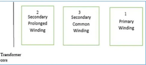
A new converter transformer is proposed along with a novel active filtering technology. Prolonged delta connection is implemented in its secondary winding. The secondary prolonged winding is denoted as Ai-ai, Bi-bi, Ci-ci (i = 1, 2). Figure 2 (b) shows this arrangement.
Figure 2: Illustrates wiring of new converter transformer
The winding denoted as a1-b1, b1-c1, c1-a1, a2-c2, b2-a2, c2-a2 is known as secondary common winding. The filters are shown in Figure 2 (a). At the connecting point of common winding and secondary prolonged winding there are double tuned filters. There is the notion of self-coupling accomplishment that is associated with the common winding
and secondary prolonged winding. It is related to something known as autotransformer series. The winding arrangement of the new converter transformer is shown in Figure 3.
Figure 3: The new converter transformer’s winding arrangement
[image:3.595.323.529.97.264.2]As presented in Figure 3, it is evident that there is winding arrangement of the new converter transformer. There are many variables associated with this. The common notations used in the modelling are shown in Table 1.
Table 1: Shows notations used in the proposed model
Notation Description
Voltage of secondary prolonged winding
Voltage of secondary common winding
Line-voltage
Prolonged winding’s RMS value of current.
RMS value of current of the common winding
Output current
Electromagnetic capacity
Output capacity Coefficient ratio
Turns number of the primary winding
Turns number of the secondary prolonged winding
Turns number of the secondary common winding
Short-circuit impedances Harmonic current source
Primary winding’s harmonic current.
The harmonic current of secondary common winding
[image:3.595.308.544.380.728.2] [image:3.595.48.291.532.684.2]With respect to Figure 3, the line-voltage is denoted as and voltage of secondary prolonged winding is denoted as
and the voltage of second common winding is denoted as
. Thus it is possible to obtain voltage phasor diagram. The output line voltage, as per cosine rule, is as in Eq. 1.
(1)
Here the output line voltage is denoted as . The voltage of secondary prolonged winding is obtained using Eq. 2.
As shown in Eq. 2, there is the usage of output line voltage computed in Eq. 1 as well. The new converter transformer is electromagnetically coupled with common winding and secondary prolonged winding. That is associated with a series and commonly used winding of autotransformer. Where there is magnetic force equilibrium arrived between common winding and secondary prolonged winding it leads to the relation shown in Eq. 3.
(3)
Here RMS value of the current of common winding and prolonged winding are denoted as , respectively. The
output current denoted as is equal to the current of
secondary prolonged winding . Then its electromagnetic capacity can be computed as in Eq. 4.
(4)
In the same fashion, the output capacity is computed as in Eq.
5.
(5)
The material utilization of ratio of the transformer can be
analysed with coefficient ratio which is computed as in Eq. 6.
(6)
[image:4.595.313.547.51.208.2]Thus new converter transformer’s ratio coefficient is computed to have the proposed filtering mechanism. Figure 4 shows new converter transformer designed with single-phase harmonic model. This model is effectively used to analyse filtering phenomenon in the new converter transformer.
Figure 4: New converter transformer’s single phase harmonic model
As shown in Figure 4, there are many notations used. The source of harmonic current is denoted as . It also reflects harmonic current of the secondary prolonged winding. The harmonic current of secondary common winding and the primary winding are denoted as , respectively. The
which denotes harmonic current in secondary prolonged
winding is capable of inducing harmonic currents , in secondary common winding and primary winding respectively. To balance , these currents are utilized. As per the ampere turn method, it is possible to get a relation as shown in Eq. 7.
(7)
The turns number associated with primary winding, secondary prolonged winding and the secondary common winding are denoted as W1, W2 and W3 respectively. From the relation in Eq. 7, it is understood that if there is balance between common winding and secondary prolonged winding a value zero is associated with . At the same time, it is known that no induced harmonic current is found in primary winding. Thus it is evident that the harmonic currents flow through secondary winding associated with the transformer.
Figure 5: Wiring arrangement of single-phase model
In order to know the proposed active filter technology, it is required to have full tuning of filter and also zero
impendence design
[image:4.595.306.549.582.690.2]International Journal of Innovative Technology and Exploring Engineering (IJITEE) ISSN: 2278-3075, Volume-8 Issue-7, May, 2019
the wiring arrangement of single-phase model shown in Figure 5. From the short circuit test [31] the impendences denoted as Z12, Z13 and Z23 that are nothing but short-circuit impendences, Eq. 8 is used to get impendence value.
(8)
[image:5.595.46.290.299.576.2]As per the winding arrangement made in Figure 5, the secondary common winding shows impendence that is almost zero when the value of resistance is ignored. This is the reason why harmonic current flows in the branch of common winding. It does mean that no induced harmonic currents are associated with primary winding. The equivalent circuit model is shown in Figure 6.
Figure 6: Shows wiring model of the proposed active filter technology
The common winding and prolonged winding are at the secondary side. Tuned filter is connected in such a way that there is connection phase that couples the two windings involved. The secondary design is specifically made to have balance of harmonic potential. This will effectively prevent the possibility of harmonic currents in the primary winding.
V. CONFIGURATIONOFTHEPROPOSEDSYSTEM
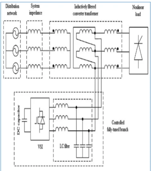
There is difference between the configuration of traditional APF and the proposed novel active filter technology. It is shown in Figure 7. As shown in Figure 7 (a), the harmonic load current is flowing into PCC. The traditional converter transformer suffers from reactive power
and harmonic components associated with load current. Thus it results in noise, vibration, increase in temperature and losses. When the active filter is connected in parallel, the rectifier gets affected due to impendence. This is the reason why power quality problems exist when traditional converter transformed is used.
[image:5.595.305.551.345.689.2]As shown in Figure 7 (b), between the non-linear load and the source, the new converter transformer is connected. The linking position between prolonged winding and common winding is used to connect the active filter. This arrangement helps in avoiding harmonics. The harmonics flows into secondary of the common winding and prolonged winding. Due to the strategic position of the filter, it is able to draw harmonic components into secondary side only. This will ensure that the primary winding is devoid of harmonics. Thus there is suppression of harmonic components at the very nearer of the non-linear load. In other words, the path of harmonic flows is confined to some area which gets rid of effects of harmonics in the power distribution systems.
Figure 7: Comparison between traditional and novel converter transformers
Figure 8: Shows results of traditional active filter: current details at load side (a), current details at the grid winding (b)
Figure 9: Results of the proposed active filtering technique: current at the load side (a), current values at grid side (b) and current at the ac side
Figure 10: Shows real and reactive power flow with traditional and new converter transformers, source side (a)
[image:6.595.48.286.394.503.2]and filter side (b)
Figure 11: Real and reactive power flow using the new converter transformer, source side (a) and filter side (b)
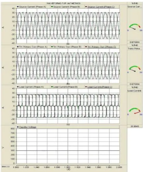
As presented in Figure 8 and Figure 9, the results of traditional filter and proposed active filter are provided. Load current with harmonic components are witnessed in Figure 8(a) and Figure 9(b) due to non-linear load present. With the results presented in Figure 8(c) and Figure 9(c), it is evident that the traditional filter and proposed active filter are able to
avoid harmonic currents entering at source side. This will help improve quality of power in distribution systems. On the contrary, it is found as shown in Figure 8(b), harmonic current can flow through the converted transformer.
With the proposed active filter technology, it is evident that the harmonic current flows are prevented from entering into the transformer. In other words, the harmonic current is suppressed at the secondary winding. From figure 10 and Figure 11, it is observed that there is zero consumption of reactive power from the source. Figure 10(b) and Figure 11(b) show that active filter generates reactive power required for the load.
Table 2: Harmonic distortion level of traditional and proposed filters
Filtering Technique % of observed harmonic distortion at the transformer’s primary winding Traditional filtering 19.70
Proposed active filter technology
0.66
[image:6.595.319.533.421.579.2]As shown in Table 2, it is understood that the total harmonic distortion exhibited by the traditional filter is very high while the proposed active filter technology showed least harmonic distortion.
Figure 12: Shows performance of the proposed active filter technology
[image:6.595.47.287.542.658.2]International Journal of Innovative Technology and Exploring Engineering (IJITEE) ISSN: 2278-3075, Volume-8 Issue-7, May, 2019
VI. CONCULSIONANDFUTUREWORK
This paper defines the problem with traditional converter transformers in the process of power distribution systems. A new converter transformer is proposed and designed in order to overcome the problems with the traditional converter transformer which makes use of filter technology. However, the proposed converter transformer is equipped with new active filter technology. Thus the proposed converter transformer effectively protects distribution systems from harmonic components. The results of simulation study revealed that the power distribution network is devoid of harmonic effects.
REFERENCES
1. G. Satyanarayana, K.N.V. Prasad, G. Ranjith Kumar, K. Lakshmi Ganesh. (2013). Improvement of Power Quality by Using Hybrid Fuzzy Controlled based IPQC at Various Load Conditions, IEEE, p1- 9.
2. Allal M. Bouzid, Josep M. Guerrero, Ahmed Cheriti, Mohamed Bouhamida, Pierre Sicard, Mustapha Benghanem . (2015). A survey on control of electric power distributed generation systems for micro grid applications. Elsever . 44, p751-766.
3. Pavlos S. Georgilakis and Nikos D. Hatziargyriou,. (2013). Optimal Distributed Generation Placement in Power Distribution Networks: Models, Methods, and Future Research. IEEE Transactions On Power Systems. 28 (3), p1- 9.
4. Jinwei He, Yun Wei Li and Frede Blaabjerg. (2014). Flexible Microgrid Power Quality Enhancement Using Adaptive Hybrid Voltage and Current Controller. IEEE Transactions On Industrial Electronics. 61 (6), p1-11. 5. Tzung-Lin Lee,Yen-Ching Wang, Jian-Cheng Li, and Josep M. Guerrero.
(2015). Hybrid Active Filter With Variable Conductance for Harmonic Resonance Suppression in Industrial Power Systems. IEEE Transactions On Industrial Electronics. 62 (2), p1-11.
6. Salem Rahmani, Abdelhamid Hamadi,Kamal Al-Haddad and Louis A. Dessaint. (2014). A Combination of Shunt Hybrid Power Filter and Thyristor-Controlled Reactor for Power Quality. IEEE Transactions On Industrial Electronics. 61 (5), p1-13.
7. Pablo Acuna,Luis Moran,Marco Rivera, Juan Dixon and Jose Rodriguez . (2014). Improved Active Power Filter Performance for Renewable Power Generation Systems. IEEE Transactions On Power Electronics. 29 (2), p1-8.
8. D.Jasmine Susila, R.Rajathy. (2013). Power Quality Enhancement Using Hybrid Active Filter. International Journal of Engineering Science and Innovative Technology. 2 (3), p1- 10.
9. Anand Singh ,Dr. Prashant Baredar . (2014). Power Quality Analysis of Shunt Active Power Filter Based On Renewable Energy Source. IEEE International Conference on Advances in Engineering & Technology Research, p1-5.
10.Kuldeep Kumar Srivastava, Saquib Shakil, Anand Vardhan Pandey. (2013). Harmonics & Its Mitigation Technique by Passive Shunt Filter. International Journal of Soft Computing and Engineering . 3 (2), p1-7. 11.Antonio Camacho, Miguel Castilla, Jaume Miret, Angel Borrell and Luis
Garcıa de Vicuna. (2015). Active and Reactive Power Strategies with Peak Current Limitation for Distributed Generation Inverters During Unbalanced Grid Faults. IEEE Transactions On Industrial Electronics, p1- 10.
12.Zhi-Xiang Zou,Keliang Zhou, Zheng Wang, and Ming Cheng. (2015). Frequency-Adaptive Fractional-Order Repetitive Control of Shunt Active Power Filters. IEEE Transactions On Industrial Electronics. 62 (3), p1- 10. 13.Vito Calderaro,Gaspare Conio, Vincenzo Galdi,Giovanni Massa and Antonio Piccolo. (2013). Optimal Decentralized Voltage Control for Distribution Systems With Inverter-Based Distributed Generators. IEEE Transactions On Power Systems, p1- 12.
14.Rajkumar Viral , D.K. Khatod. (2015). An analytical approach for sizing and siting of DGs in balanced radial distribution networks for loss minimization. Elsever . 67, p191-201.