International Journal of Innovative Technology and Exploring Engineering (IJITEE) ISSN: 2278-3075, Volume-8, Issue- 6S4, April 2019
Abstract—Industries encourage the use of low-cost compact and easily controllable equipment’s to implement automation due to the lack of skilled labors and low productivity. This demands the need for more efficient and affordable novel mechanisms and processes. In this paper, the kinematic analysis of a 3-PPSS (P— prismatic joint, S- spherical joint) parallel manipulator having an equilateral mobile platform is explained. The Kinematic analysis is done using the Modified Denavit-Hartenberg (DH) modelling technique. The inverse kinematic equations are further solved using Levenberg-Marquardt Algorithm to obtain an exact solution for the joint variables corresponding to an instantaneous pose of the end effector. Static structural analysis is done using ANSYS software to determine the deformations and stresses induced. Optimum dimensions are chosen for the manipulator based on this analysis. Finally, an ARDUINO based control is implemented to manipulate the mobile platform by controlling the active prismatic joints.
Index Terms— Denavit-Hartenberg (DH) Modelling, Dimensional Synthesis, Forward Kinematics, Parallel manipulator, Static structural analysis
I. INTRODUCTION
Parallel manipulators are mechanisms having links connected to form closed loop chains. There are many recent developments in the field of parallel manipulators compared to serial manipulators. Higher rigidity, stiffer structure and the ability to carry larger payloads are the major attractions of parallel manipulators. These mechanisms are now gaining interests in industries, medical fields, space centers, etc. The development of parallel mechanisms can be traced back to the ‟40s. At the time Gough [1] designed the tyre testing machine using a parallel mechanism. Thereafter, different designs for parallel robots came up for various applications. It is desired to have simple and lighter weight designs since the energy consumptions can be reduced, control made easier and achieve faster motions. Merlet [2] solved the forward kinematics for the Gough mechanism numerically using interval analysis method. The Stewart platform is a modified form of Gough mechanism, popularly known as Gough-Stewart mechanism which is used for flight or other vehicle simulations. Domagoj and Budin [3] analysed both the forward and inverse kinematics for the Gough-Stewart mechanism. The author formulated the inverse kinematic equations of the robot geometrically. Wang [4] explained the direct numerical solution to the forward and inverse kinematics of
Revised Manuscript Received on April 12, 2019.
Mr. SoorajSukumar K, Department of Mechanical Engineering, NIT Calicut. Kerala, India.
Mervin Joe Thomas, Department of Mechanical Engineering, NIT Calicut. Kerala, India.
Dr. Sudheer A.P., Department of Mechanical Engineering, NIT Calicut. Kerala, India.
Dr. M.L.Joy, Department of Mechanical Engineering, NIT Calicut.Kerala, India.
the Gough-Stewart platform. The author derived a linear relationship between the small changes in the joint variables and the resulting small motions in the platform. This method cannot be used in general for solving kinematics of all parallel manipulators. Fenget al. [5] explained the inverse kinematics of a 5 DoF parallel manipulator which consists of five legs connecting the moving platform and the fixed platform. The fifth limb has two passive universal joints that restrict the rotational motion of the platform. The remaining four legs have one active sliding joint, a passive, spherical and universal joints at each end respectively. The author solved the complete kinematics of the mechanism using a geometrical approach. The difficulties involved in controlling the universal joint in the mechanism makes it less suitable for many applications. Zhang et al. [6] explained the kinematics and dynamics of a parallel manipulator having 3 DoF. The author used cylindrical coordinates to describe the position and orientation of the moving platform. The mechanism is modelled dynamically using the Lagrangian formulation. However, the complex nature of the embedded mechanism makes it less suitable for many applications. Zhengsheng et al. [7] developed the closed form dynamic model of a parallel manipulator using the Lagrangian formulation with Lagrangian multipliers. The mechanism considered is a simple 2 DoF parallel manipulator. The author incorporated the effect of flexible motions happening in linkages during working into the mathematical model. The Lagrangian multiplier for the mechanism is defined using two holonomic constraints present within the geometry. The author also proposed a composite control scheme for the trajectory planning of the end effector. Leroy et al. [8] introduced a 3 DoF parallel manipulator for medical applications. The dynamic equations for each leg are written separately and finally coupled together using suitable constraints. Each leg is approximated as a serial manipulator. The constraints are reintroduced into the model by the use of Lagrangian multipliers.Pedrammehr et al.[9] developed a 6 DoF parallel manipulator called Hexarot. Hexarot robot comprises of six arms which is collectively connected to the triangular platform. The mechanism is modelledkinematically in terms of Euler angles. The mechanism is modelled dynamically using the Newton-Euler approach and verified using ADAMS. The author presented a simulation study for defined joint motions and correspondingly compared the results obtained from the dynamic model and ADAMS. Chablatet al. [10] explained the inverse kinematics and dynamics of an orthoglide parallel robot
Kinematics, Structural Analysis and Control
of 3-PPSS Parallel Manipulator
which is designed for highly precise applications. The mechanism has three DoF and the inverse kinematics is solved using the geometrical approach. The mechanism is modelled dynamically using the principle of virtual work. Mario et al. [11] proposed a planar parallel mechanism and used screw theory approach to obtain the kinematic equations. The author has not detailed on the synthesis of the mechanism and the optimisation of the work volume. Dimensional synthesis is done to determine the link dimensions for the mechanism corresponding to maximum work volume.Liao et al. [12] developed a 3 DoF RRR robotic mechanism for pick and place operations. The inverse kinematics and workspace for the mechanism are analysed using geometrical approach. The optimum design for the mechanism is explained considering the objective to maximize the work volume. Li and Xu [13] modelled the
3-PRS parallel manipulator. The mechanism is
modelledkinematically using the screw theory and further used to plot the workspace. The authors have derived the Jacobian matrix for the mechanism to analyse the velocity variations of the end effector considering suitable geometrical constraints. Calinet al. [14] developed a six DoF parallel robot called HEXA. The author introduced a new control architecture that is directly implemented into the robot PLC to permit real-time control. The HEXA robot prototype is tested to illustrate the performance of the robot and its control system.
Despite extensive researches happening in the field of parallel mechanisms, most mechanisms have limited workspace, complicated architecture, difficulties in solving forward kinematics, etc. It is seen in many literatures that either geometric or screw theory approaches are used to obtain the kinematic model of the mechanism. Solving for the direct kinematics by these approaches is tougher and difficult to understand because of the complexities involved in the method. Denavit-Hartenberg (DH) modelling technique is widely used in obtaining the kinematic model for serial manipulators. However, the use of DH modelling technique in parallel spatial mechanisms is seldom used.Therefore, in this paper, the novel 3-PPSS parallel mechanism is modelled using the modified DH technique by considering suitable holonomic constraints present within the architecture. This method is more direct, straight forward and easy to apply in any parallel mechanisms for solving the forward and inverse kinematics. The closed mechanism is opened and then modelled individually using the conventional DH technique. The individual legs are then finally coupled together to account for the closed parallel mechanism. The Levenberg – Marquardt Algorithm is used to solve for the inverse kinematics numerically. The optimiseddimensions for the critical parts of the manipulator is determined from the static structural analysis done using ANSYS.
II. CONCEPTUAL DESIGN OF 3-PPSS MANIPULATOR
The CAD model of the proposed mechanism is shown inFig. 1. The three legs are coupled together at the equilateral triangle shaped mobile platform. Modified Grübler–Kutzbach criterion is used to determine the number
of DoF for the mechanism theoretically. According to this criterion,
𝐷𝑜𝐹 = 𝑏 𝑛 − 𝑔 − 1 + 𝑓𝑖− 𝑓𝑖𝑑 + 𝑠
𝑔
𝑖=1 (1)
where „b‟ is the number of DoF in three-dimensional space, „n‟ is the number of elements, „g‟ is the number of joints, „fi‟ is the number of DoF of the ith joint, „fid‟ is the
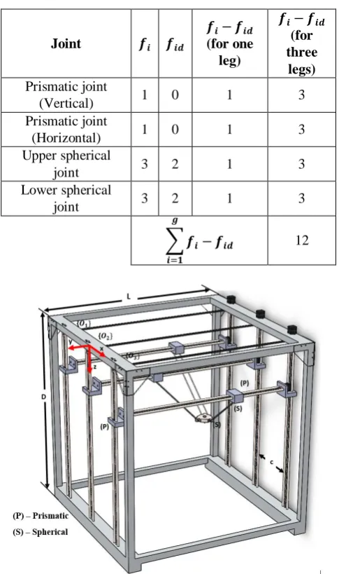
number of identical DoF at each joint and „s‟ is the number of passive joints. The value of „b‟ for spatial mechanisms is 6. The values of „n‟, „g‟ and „s‟ for the 3-PPSS mechanism are 11, 12 and six respectively. The values of fi and fid are
[image:2.595.306.549.235.645.2]given in table 1. On substituting the above values into equation. 1, the number of DoF for the mechanism is computed theoretically as 6.
Table 1: fiand fid values for the 3-PPSS mechanism
Joint 𝒇𝒊 𝒇𝒊𝒅
𝒇𝒊− 𝒇𝒊𝒅
(for one leg)
𝒇𝒊− 𝒇𝒊𝒅
(for three
legs)
Prismatic joint
(Vertical) 1 0 1 3
Prismatic joint
(Horizontal) 1 0 1 3
Upper spherical
joint 3 2 1 3
Lower spherical
joint 3 2 1 3
𝒇𝒊− 𝒇𝒊𝒅 𝒈
𝒊=𝟏
12
Fig. 1: CAD model of the 3-PPSS parallel manipulator with an equilateral triangular mobile platform III. KINEMATIC MODELLING USING
MODIFIED DH METHOD
The kinematic analysis for the 3-PPSS manipulator is done using the modified DH method. DH method is a well-established method to model serial manipulators. This method is easier to understand and
International Journal of Innovative Technology and Exploring Engineering (IJITEE) ISSN: 2278-3075, Volume-8, Issue- 6S4, April 2019
the moving platform.
However, in case of parallel mechanisms a suitable coupling equation must be incorporated to account for the closed configuration of the mechanism. Initially, the closed mechanism is split into individual open chains and the DH algorithm is applied to each leg to get the end effector pose. Poses of three PSS individual legs are coupled together using geometric constraints to obtain the inverse kinematics of the closed chain. Let „O2‟ be the global frame with which the
[image:3.595.314.533.178.374.2]position of the end effector is to be determined. The final pose obtained by this method will include all active and passive joint variables in the mathematical expression unlike the case derived from other modelling techniques. The end effector platform is an equilateral triangle as depicted in Fig. 2.
Fig. 2 Equilateral shaped triangular mobile platform
Poses of (1), (2) and (3) respectively from O1, O2 and O3
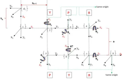
are the same because of similar geometry. Hence, the frame assignment is common to all individual legs. The frame assignment of a single leg is as shown in Fig. 3. Each of the spherical joints aremodelled as a combination of three revolute joints having the same origin. Finally, the end effector pose of all three legs is determined with respect to the global frame O2.
Fig.3DH Frame assignment for a single leg
The DH parameters assigned between two consecutive frames are listed in table 2 and is substituted into the standard transformation matrix to obtain relations between the frames. The pose of the eighth frame from the zeroth
frame for each leg is derived from the following relationship,
𝑇𝑂8𝑖=𝑇𝑂1𝑖. 𝑇12. 𝑇23. 𝑇34 .𝑇45. 𝑇56. 𝑇67. 𝑇78 (2)
Frame {8} represents the last frame at the spherical joint on the mobile platform. It is desired to obtain the pose of the end effector tip from O2. Therefore, an additional frame {9}
is assigned at the tip of the end effector. The pose of the end effector tip from global frame O2 for the middle leg is
obtained as follows,
𝑇𝑂92
𝑀= 𝑇𝑂2
8 𝑀.
1 0
0 1
0 0
0 𝑛 0 0 0 0
1 𝑏 0 1
[image:3.595.63.274.283.379.2](3)
Table 2DH Parameter table for a single leg
Link 𝜽
(degree) d a
𝜶 (degree)
1 0 𝑥𝑘 0 90
2 0 𝑥𝑘+1 0 90
3 𝜃3+ 90 0 0 90
4 𝜃4− 90 0 0 −90
5 𝜃5 0 a 90
6 𝜃6+ 90 0 0 −90
7 𝜃7− 90 0 0 −90
8 𝜃8 0 0 0
Similarly, the pose of end effector tip from the global frame O2 along the left and right legs are given by equations 4 and 5 respectively.
𝑇𝑂92
𝐿= 𝑇𝑂2
𝑂1
. 𝑇𝑂1
8 𝐿. 𝑇8
9
𝐿 (4)
𝑇𝑂92
𝑅= 𝑇𝑂2
𝑂3. 𝑇
𝑂3
8 𝑅. 𝑇8
9
𝑅 (5)
Inverse kinematics deals with the determination of the joint variables corresponding to the known pose of the mobile platform. In the previous section, the pose of the end effector tip is determined separately from the global frame O2 assuming each leg to be individual serial chains. This
implies that equations (3), (4) and (5) can be equated to the desired pose matrix to couple the three legs and obtain the closed form inverse kinematic solution for the 3-PPSS manipulator. The 3-PPSS manipulator consists of 24 variables in total. Holonomic constraints present within the geometry is used to account for the other set of six equations. These equations couple the three legs in the mathematical model which is represented in equations 6 and 7.
{[ 𝑆𝐿𝑋 𝑖− 𝑆𝐿𝑋 𝑗]2+ [ 𝑆𝐿𝑌 𝑖− 𝑆𝐿𝑌 𝑗]2+
[ 𝑆𝐿𝑍 𝑖− 𝑆𝐿𝑍 𝑗]2} = 𝑘2𝑖, 𝑗 =1, 2, 3; 𝑖 ≠ 𝑗 (6)
𝑆𝐿𝑋 𝑖− 𝑆𝑈𝑋 𝑖 2+ 𝑆𝐿𝑌 𝑖− 𝑆𝑈𝑌 𝑖 2+
[image:3.595.62.274.526.663.2]Table 3 ANSYS simulation results Sl.
No. Component Material
Dimensions (in m) Equivalent
stress (MPa)
Total deformation
(mm) Before optimization After optimization
1 Platform Stainless steel Thickness =0.02 Thickness =0.01 30.892 0.01182
2 Connecting
link Stainless steel Diameter =0.006 Diameter = 0.008 65.541 0.071569
3 Slider Nylon 6,6 Width =0.06
Height =0.05
Width =0.04
Height =0.04 39.243 0.010813
4 Horizontal link Stainless steel + Nylon 6,6
Width =0.075 Height =0.075 Rod diameter =0.015
Width =0.06 Height =0.055 Rod diameter =0.012
56.774 0.16353
5 Frame Mild steel 0.04 x 0.04 x 0.004
Rod diameter= 0.015
0.032 x 0.032 x 0.0026
Rod diameter= 0.012 36.361 0.01366
where „SUX‟ and „SLX‟ represents the upper and lower
spherical joints in the mechanism, „k‟ is the length of side of the mobile platform and „a‟ is the length of the connecting link. Iterative Levenberg-Marquardt Algorithm (LMA) is used to solve the set of 24 non-linear equations. The LMA is a curve fitting method that adaptively varies the parameter updates between Gradient descent method and the Gauss-Newton method [16]. In this method, the set of equations are represented as „f(x) = 0‟, where x represents all the joint variables, x= [x1x2x3…x24]T. The objective function of this algorithm is
to minimise the RHS and approach to zero. The algorithm stops either when the RHS lies between 0 and 0.01or when the iteration number reaches the maximum (Kmax)
assigned. The algorithm will return the values of x during the last iteration as the solution when either of the above conditions comes first.
IV. STATIC STRUCTURAL ANALYSIS USING ANSYS WORKBENCH 18.2
The static structural analysis is done to compute the effects of static loading conditions on the robot structure. It is done to determine the maximum deformation and stress-induced at extreme loading conditions on the robotic mechanism. The simulation results can be further used to identify the weaker parts and make the necessary modifications to avoid the failure of the mechanism. The optimum dimensions for every component are determined on specifying the maximum and minimum limits possible. The optimised dimension is chosen to correspond to the dimension having the least stresses and deformations induced within the mechanism. Table 3 shows the simulation results of every component and their corresponding dimensions before and after optimisation. The materials are assigned accordingly from the material library available in the ANSYS. The analysis is done by applying a static load of 50 N at the centre of the moving platform. The corresponding deflections induced in the system is determined by the simulation study. The dimensions of individual parts like the smooth shafts, lead screws, etc. are changed accordingly to avoid excessive bending or deflections.
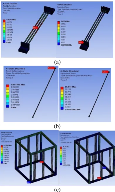
Excessive deflections can interfere into the smooth motions of the sliders along the linear smooth shafts. Fig. 4 (a), (b) and (c) show the maximum stress and deformations induced in the critical parts of the mechanism. The maximum deflection induced in the rod of the horizontal link is 0.16353 x 10⁻³m. The horizontal link consists of three guide rods made of stainless steel and two end mounts made of Nylon 6,6. This deflection on the rod does not hinder the motion of the sliders. The deflections induced at all other parts is small and is within safer limits. The analysis is done when the moving platform is in the exact middle. At this position, the deflection acting on the horizontal link is maximum. The maximum stress (von-mises) induced for the same load and position is 65.541 MPa acting on the connecting link. The link dimensions obtained from the optimisation based on strength is further used to construct the prototype of the mechanism.
V. ARDUINO BASED CONTROL OF THE
PARALLEL MANIPULATOR
The 3-PPSS parallel manipulator consists of six motors to be controlled independently for manipulating the mobile platform. An ARDUINO MEGA 2563 is used to enable the automation of the parallel manipulator for a desired path of the end effector tip. The DRV-8825 motor drivers are used to bridge between the ARDUINO and the individual motors with the power supply. The user defines the path to be followed by the end effector via the MATLAB interface in laptop connected to the system. The end effector tracks the trajectory based on the inverse kinematics. The slider distances obtained from inverse kinematics for every instant is further used to calculate the angular rotations necessary for each motor using the following equation,
𝜃 =2𝜋(∆𝐿𝑖)
International Journal of Innovative Technology and Exploring Engineering (IJITEE) ISSN: 2278-3075, Volume-8, Issue- 6S4, April 2019
(a)
(b)
[image:5.595.65.262.48.378.2](c)
Fig. 4 Stresses and Deformations induced in the horizontal link, connecting link and frame after
optimization
where „p‟ is the pitch of the lead screw and ∆Li is the
slider displacement for each leg. The angular rotations calculated is then given as input to the ARDUINO to control each motor. The schematic diagram of the control flow diagram is shown in Fig. 5.
Fig. 5 Control flow diagram for automation VI. RESULTS AND DISCUSSION
A novel 3-PPSS parallel manipulator is proposed in this paper. The kinematic modeling using modified DH representation and Static structural analysis using ANSYS workbench is explained. The proposed design is simple which has six active prismatic joints and six passive spherical joints. Initially, the mechanism is modelled using DH parameters for each leg and suitable coupling equations are used to incorporate the closed form architecture of the parallel mechanism. The workspace can be plotted using the forward kinematic relations obtained from the DH model. The static structural analysis is done to determine the optimum link dimensions to withstand the loads and stresses acting on the device. The maximum deflection induced for a load of
50 N is 0.16353 x 10⁻³m on the horizontal link and maximum stress induced is 65.541 MPa acting on the connecting link. Both the values are within safe limits and therefore be considered for actual fabrication.
VII. CONCLUSION AND OUTLOOK OF WORK
The proposed 3-PPSS mechanism is suitable for different applications such as pick and place operation, electronic assembly, machining and service industries, etc. Optimum design for the mechanism is introduced for the applications mentioned above. All the active and passive joints are considered in the complete modelling of the robot. The static structural analysis gives static failure analysis for the critical parts within the mechanism. This mechanism can also be effectively used for health care applications such as scanning, physiotherapy, medical applications, etc. by changing the upper and lower bounds of the link dimensions and using suitable end effector. Dynamic modeling is to be done to determine the joint forces and torques acting. Actuator selection and controller design can be done based on this dynamic model. By incorporating suitable actuators at the active joints, sensors and controller, the mechanism can be made autonomous for various applications.
REFERENCES
1. Gough.V.E,” Contribution to discussion to papers on
research in automobile stability and control and in type performance”, Proc Auto DivInstn Mech. Eng,1957, pp 392–395
2. Merlet.J.P,” Solving the Forward Kinematics of a
Gough-Type Parallel Manipulator with Interval Analysis”, The International Journal of Robotics Research, Vol. 23 No. 3, 2004, pp. 221-235
3. Domagoj.J, and Budin.L, “Forward kinematics of a Stewart
Platform Mechanism”, Journal of Mechanical Design, Vol. 115 No. 4, 2002, pp. 277-282
4. Wang.Y, “A direct numerical solution to forward
kinematics of general Stewart-Gough platforms”, Robotica Journal, Vol. 25 No. 1, 2007, pp.121–128
5. Feng.G, Peng.B, Zhao.H, Li.W, “A novel 5-DOF fully
parallel kinematic machine tool”, International Journal for Advanced Manufacturing Technology, Vol. 31 No. 1,2006, pp. 201–207, DOI 10.1007/s00170-005-0171-1
6. Zhang.J, Wang.X, Jiang.N, Li.W, “Kinematics and
Dynamics for a 3-DOF Parallel Manipulator with Limbs of Embedding Structures”, ICIRA, Proceedings in Springer, 2013, pp: 63-73
7. Zhengsheng.C, Minxiu.K, Ming.L, Wei.Y,” Dynamic
Modelling and Trajectory Tracking of Parallel Manipulator with Flexible Link”, International Journal of Advanced Robotic Systems, Vol. 10 No. 1, 2013, DOI: 10.5772/56765
8. Leroy.N, Kakosy.A.M, Perroquett.W, ”Dynamic modelling
of a parallel robot, application to surgical simulator”, Proceedings of IEEE, international conference of robotics and automation, 2013, pp:14-19
9. Pedrammehr.S, Danaei.B, Abdi.H, Masouleh,
10. Chablat D., Wenger P., Staicu, S., “Dynamics of the Orthoglide parallel robot”, UPB Scientific Bulletin, Series D: Mechanical Engineering, 2009, Vol. 71 No. 3, pp. 3-16.
11. Mario.A.G.M, Roger.E.S, Jaime.G.A, “Kinematics and
Dynamics of a Translational ParalleL Robot Based on Planar Mechanisms”, Machines Journal, 2016, Vol. 4 No. 22, doi:10.3390
12. Liao.B and Lou.Y,” Kinematics and optimal design of a
novel 3-DoF parallel manipulator for pick-and-place applications”, International Journal for Mechatronics and Automation, Vol. 3 No. 3, 2013, pp.181–190.
13. Li.Y and Xu.Q, “Kinematic analysis of a 3-PRS parallel
manipulator”, Robotics and Computer-Integrated
Manufacturing Journal, 2006, pp.395-408.
14. Calin.V, DoinaPisla, Florin.C, Bogdan.C, Adrian.P,
Nicolae.P, “Development of a control system for a HEXA parallel robot, IEEE Transactions, Research centre for Industrial robots simulation and testing, Napoca, 2016
AUTHORS PROFILE
SoorajSukumar K is aMTech post graduate student specialized in Manufacturing engineering, under the Mechanical Engineering Department, National Institute of Technology Calicut. (NITC). He is involved in many on-going projects happening within the institute related to automation and Control, Gesture Control, Human Interfacing with robots and manipulator development.
Mervin Joe Thomas is a Ph.D. scholar in the field of Robotics under the Mechanical Engineering Department, National Institute of Technology Calicut (NITC). His research interest is focused mainly on the development of parallel/hybrid manipulators that is suitable for precise applications. Various aspects such as the singularity analysis, workspace optimisation, controller design and development of low-cost manipulators are other primary aspects considered for research. He also guides UG and PG students working in the fields of robotics and automation.
Dr. Sudheer. A. P is currently an Assistant Professor, Mechanical Engineering, National Institute of Technology Calicut (NITC). He is in teaching, research and academic administration for the last 20 years. He has nearly 30 publications in International and national journals and conferences. He is guiding M.Tech and PhDs students. He has filed for four patents in the area of robotics. His research interests are kinematics, dynamics and control of robotics, mobile robotics and vision systems. He is a member of “the Robotics Society-India"(TRS-India) and ISTE. Presently he is the editor of TRS-India.