Abstract: Due to existence of haze, the image quality is degraded in the environment. Removal of haze is called dehazing. To dehaze an image Dark Channel Prior is recommended. Dark Channel Prior is an observation, that an image has few pixels whose intensity value is very small or near to zero in most non-sky patches. Such pixels are referred to as dark pixels. Dehazing through Dark Channel Prior is accomplished using four major steps. The steps include estimating atmospheric light, estimating transmission map, refinement of transmission map and image reconstruction. Incorrect estimation of transmission map may lead to some problems. These problems include false textures and blocking artifacts. Many methods are developed to further sharpen transmission map. Here transmission map is refined using soft matting, guided filter and bilateral filter. The comparison of dehazing methods has become difficult due to scarce availability of ground truth images .So we used I-HAZE, a new data set containing 35 picture pairs of hazy pictures and their respective ground truth pictures. A significant benefit of I-HAZE data set is that it allows us to compare different refinement methods used for dehazing with SSIM, PSNR and RMSE which are used for the measurement of finally obtained reconstructed image quality after the removal of haze.
Keywords: Dark Channel Prior, Dehazing
I. INTRODUCTION
Outdoor pictures are poorly visible due to haze. Haze happens because atmospheric particles are absorbed and dispersed. Due to poor visibility both consumer photography and computer vision applications get effected. A significant process is regarded to enhance the efficiency of computer vision applications. To conduct dehazing, the techniques described previously require numerous pictures. Polarization based techniques [1]-[3] remove haze using various pictures with distinct degrees of polarization and weather based techniques[4],[5] remove haze using various pictures which are captured under distinct weather conditions Because of this, focus is increasing on single image based dehazing techniques. A technique suggested by Tan [6] is based on the observation that the haze-free picture contrasts more than the picture containing haze. The scene albedo is estimated by a
Revised Manuscript Received on October 05, 2019.
* Correspondence Author
G Harish Babu*, Department of Electronics and Communication
Engineering, CVR College of Engineering, Hyderabad, India. Email: harish.sidhu12@gmail.com
M Kavya, Department of Electronics and Communication Engineering,
CVR College of Engineering, Hyderabad, India. Email:
kavya241996@gmail.com
N Venkatram, Dean Academics, Koneru Lakshmaiah Educational
Foundation, India.
technique suggested by Fatall [7] assuming transmission and ground shading are uncorrelated.
Dark Channel Prior method based removal of haze from picture was suggested by He [8]. The Dark Channel Prior is a property of dark pixels in which intensity values of some pixels are very low or close to zero expect for sky region. Because of its efficacy, the DCP has been embraced by most latest dehazing methods. The Dark Channel Prior dehazing methods consists of four main steps: estimating atmospheric light, estimating transmission map, transmission map refinement and image reconstruction. In this we perform transmission map refinement using soft matting, guided filter and bilateral filter.
II. HAZEREMOVALBASEDONDARKCHANNEL
PRIOR
The formation of haze in an image is described using following equation:
where x shows the coordinates of the image, represents image with haze ,J is the picture which do not contain haze and is atmospheric light and is the amount of light that’s not scattered into atmosphere and reaches a camera which is also known as transmission.
The transmission map can be stated as
where the scattering coefficient is represented using and the scene depth is represented using d.
The goal of removing haze from a picture is to recover J, and from the image containing haze called . The estimation of and is not easy. Generally varies according to scene depth so the number of image pixels and number of unknowns are same. Therefore it is highly impossible to estimate from without any assumptions.
III. DARKCHANNELCONSTRUCTION
Dark Channel Prior is built on the assumption of images which don’t contain haze in outdoor environment. According to this assumption there are few pixels in which the intensity value of these pixels is very less or close to zero. Such pixels are called as dark pixels. The dark channel is well-defined based on this observation. is defined to be dark channel for image J where is as:
Dark Channel Prior Based Image Dehazing using
Different Transmission Map Refinement
Methods
where is a patch positioned at x, is the
intensity of channel color. Dark Channel of an image is generally obtained using two minimum operators.
Conferring to the dark channel concept, J is image without haze so J’s dark channel intensity is of nearly zero value:
This observation is known as Dark Channel Prior. The factors like shadows, dark objects or surfaces and colorful objects contribute for low intensity in dark channel.
IV. ESTIMATIONOFATMOSPHERICLIGHT The direct equation to determine the atmospheric light, is as follows according to [9], [10]
However, this method cannot estimate the atmospheric light correctly when image contains bright objects. Therefore pixels with top 0.1% values of dark channel are carefully chosen as haze opaque. After selecting, the pixel value with maximum intensity is the value of which is nothing but atmospheric light.
V. ESTIMATIONOFTRANSMISSIONMAP The image haze equation given in (1) is normalized with :
It is supposed that in patch , transmission is constant. Transmission is now denoted as .Now we calculate dark channel for (6) on both sides. The equation obtained is as follows:
According to Dark Channel Prior approximation as in (4), can now be as follows:
The image may not look naturally when haze from an image is entirely removed as mentioned in [8].Therefore we need to retain some quantity of haze. To achieve this a constant
(0 is used and the equation is modified as follows:
VI. REFINEMENTOFTRANSMISSIONMAP
False textures is the problem that occur due to incorrect estimation of transmission map. Blocking artifacts is also an issue due to incorrect estimation of transmission map. To evade these problems methods are developed for sharpening of transmission map. Here we used bilateral filter, soft matting and guided filter for transmission map refinement.
A. Refinement using Bilateral Filter
Bilateral filter uses neighboring pixel’s weighted values. It is used as smoothening filter such that the edges are preserved.
The bilateral filter transmission map refinement equation is given using as:
(10)
Where is spatial kernel with standard deviation .
is range kernel with standard deviation B. Refinement using Soft Matting
Equation (1) is analogous to equation of matting [11].For obtaining refined transmission map we minimize the following cost function:
where is weight which controls data term. The transmission map that need to be refined is represented as .The solution for equation (11) is as follows:
(12) where an identity matrix is represented using U.
Soft matting based transmission map refinement method generally takes more time for refinement which is a disadvantage.
C. Refinement using Guided Filter
The original Dark Channel Prior used for the removal of haze [8] is replaced with guided filter [12] - [14] as an alternative of soft matting to speed up the refinement of transmission map. The haze image is guidance image which is used by guided filter. We take up as linear transform of hazy image in window :
(13) where the coefficient and are constant in .
The solution for ( is obtained as
, (14)
Where is mean and is variance of input guidance image I in window . is the number of pixels in and
The transmission map that need to be refined using guided filter is given using as
where and .They
represent average of coefficients obtained at pixel x.
VII. CONSTRUCTIONOFFINALDEHAZEIMAGE When atmospheric light and transmission map are estimated the dehaze image is finally obtained using (1) as
To avoid low value in denominator most of Dark Channel Prior based haze removal techniques used typical value of
as 0.1[10].
[image:3.595.311.542.108.355.2]VIII. QUANTITATIVEEVALUATIONOFSSIM, PSNR&RMSEUSINGI-HAZEDATASET SSIM, PSNR and RMSE for different transmission map refinement methods using soft matting, guided filter and bilateral filter is done using a dataset known as I-HAZE dataset [15]. From I-HAZE dataset seven images are selected randomly and their corresponding SSIM, PSNR and RMSE are evaluated for different transmission map refinement methods using soft matting, guided filter and bilateral filters. Table - I: Quantitative Evaluation using Soft Matting for
Refinement Image
Set Number
Refinement using Soft Matting
SSIM PSNR RMSE
02 0.8692 17.5018 33.9978
14 0.7935 17.5140 33.9501
15 0.7756 16.4629 38.3171
16 0.8087 18.0681 31.8518
23 0.7530 14.1575 49.9648
31 0.7366 18.3645 30.7833
34 0.8083 17.1314 35.4790
Table - II: Quantitative Evaluation using Guided Filter for Refinement
Image Set Number
Refinement using Guided filter
SSIM PSNR RMSE
02 0.8137 14.8371 46.2047
14 0.7714 17.7334 33.1030
15 0.7874 18.1484 31.5588
16 0.7949 17.8544 32.6454
23 0.7751 14.7354 46.7485
31 0.7487 19.8635 25.9038
34 0.7688 16.6981 37.2935
Table - III: Quantitative Evaluation using Bilateral Filter for Refinement
Image Set Number
Refinement using Bilateral filter
SSIM PSNR RMSE
02 0.5055 8.4264 96.653
14 0.6105 10.9690 72.125
15 0.5536 10.8893 72.790
16 0.6051 12.0955 63.352
23 0.3446 8.8861 91.671
31 0.4946 11.0709 71.284
[image:3.595.75.265.229.496.2]
[image:4.595.76.520.48.620.2]
a)Hazy Image b) Soft Matting c)Guided Filter d)Bilateral Filter e)Groundtruth Image Fig. 1: The first column shows the hazy images .The last column shows the ground truth. The other columns from left to
right show the results obtained using different refinement methods of Matting, Guided Filter and Bilateral Filter of I-HAZE dataset for the set of images {2},{14},{15},{16},{23},{31},{34} respectively from 35 image pairs of I-HAZE
Fig. 2: SSIM Comparison using different refinement methods
[image:5.595.51.291.50.308.2]Fig 3 represents PSNR comparison between different refinement methods using soft matting, guided filter and bilateral filter. On the basis of graph, it can be said that refinement using guided filter has better PSNR value in average when compared with the soft matting based refinement and bilateral filter based refinement.
Fig. 3: PSNR Comparison using different refinement methods
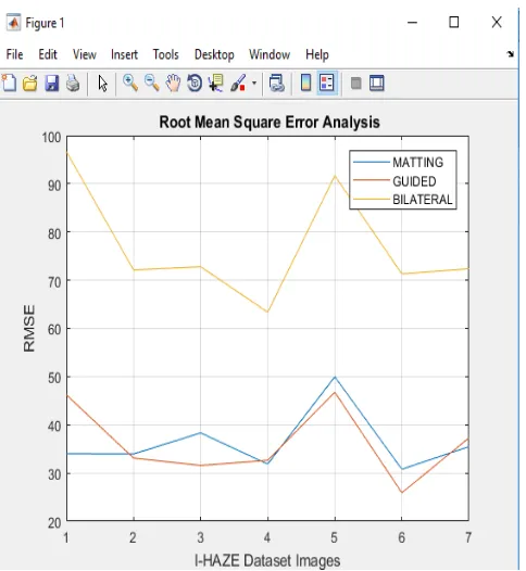
Fig 4 represents RMSE comparison between different refinement methods using soft matting, guided filter and bilateral filter. On the basis of graph, it can be said that refinement using soft matting and guided filter has least RMSE value.
Fig. 4: RMSE Comparison using different refinement methods
IX. CONCLUSION
To evaluate the refinement of dehazing methods using soft matting, guided filter and bilateral filter quantitatively we need to compare the final reconstructed images with ground truth images.SSIM is also calculated along with PSNR and RMSE.The SSIM values generally yields values in the range of [-1,1].A maximum value of 1 is obtained between two similar images.
Based on the results obtained using refinement methods we can conclude that soft matting performs the best in terms of SSIM but the time taken for transmission map refinement is more when compared with the other two refinement methods. The guided filter has better PSNR values when compared to other two refinement methods. The guided filter performs faster when compared with the other two refinement methods of soft matting and bilateral filter. The results obtained also demonstrate that bilateral filter is not really operative in terms of its values obtained for SSIM, PSNR and RMSE.
The higher values of RMSE and relatively lower values of SSIM and PSNR measures illustrate the fact about the difficulty of single image based haze removal process and provides us a scope to develop advanced dehazing algorithms.
REFERENCES
1. YY Schechnner, SG Narasimhan, SK Nayar, “Polarization based vision through haze.Appl.Optics”, 42(3),511-525 (2003)
2. YY Schechnner, SG Narasimhan, “Instant dehazing of images using polarization”, in Proceedings of IEEE Computer Society Conference on Computer Vision and Pattern Recognition (CVPR, Kauai, 2001), pp.25-332
[image:5.595.48.292.400.660.2]Photo
4. SG Narasimhan,SK Nayar, “Contrast restoration of weather degraded images”, IEEE Trans.Pattern Anal. Mach. Intell, 25(6), 713-724 (2003)
5. SK Nayar, SG Narasimhan, “Vision in bad weather”, in Proceedings of the 7th IEEE International Conference on Computer Vision (ICCV, Kerkyra, 1999), pp.820-827
6. RT Tan, “Visibility in bad weather from a single image”, in Proceedings of IEEE Computer Society Conference on Computer Vision and Pattern Recognition, (CVPR, Anchorage, 2008), pp. 1-8 7. R Fattal, “Single image dehazing”, ACM Trans. Graph, 72(3),
72:1-72:9 (2008)
8. K He. J Sun. X Tang, Proceedings of IEEE Computer Society Conference on Computer Vision and Pattern Recognition (CVPR,Miami,2009), pp.1956-1963
9. J Long, Z Shi, W Tang, “Fast haze removal for a single remote sensing image using dark channel prior”, in Proceedings of International
Conference on Computer Vision in Remote Sensing
(CVRS,Xiamen,2012), pp.132-135
10. X Lv, W Chen, IF Shen, “Real –time dehazing for image and video” ,in Proceedings of the 18th IEEE Pacific Conference on Computer Graphics and Applications (HangZhou,2010), pp.62-69
11. A Levin, D Lischinski, Y Weiss, “A closed-form solution to natural image matting”, IEEE Trans.Pattern Anal.Mach.Intell.30(2), 288-242 (2008)
12. Y Linan, P Yan, Y Xiaoyuan, “Video defogging based on adaptive tolerance”, TELKOMNIKA Indonesian Journal of Elec. 10(7),1644-1654 (2012)
13. MS Sandeep, “Remote sensing image dehazing using guided filter”, IJRSCSE.1 (3),44-49 (2014)
14. Z Lin, X Wang, “Dehazing for image and video using guided filter”, Appl.Sci.2(4B),123-127 (2012)
15. Ancuti C, Ancuti C.O, Timofte R, De Vleeschouwer C,(2018) “I-HAZE: A Dehazing Benchmark with Real Hazy and Haze-Free Indoor Images”
AUTHORSPROFILE
G Harish Babu, received his B.Tech degree in the
Department of Electronics & Communication Engineering under Jawaharlal Nehru Technological University, India, 2013. He received M.Tech degree in Embedded Systems from K L University, Andhra Pradesh, India in 2015 and currently doing research work as a Part time research scholar in the department of Electronics & Communication Engineering in Koneru Lakshmaiah Education Foundation, Andhra Pradesh, India. He is currently working as an Assistant Professor in CVR Engineering College, Hyderabad. His research interests are on Image Processing, Machine learning.
Dr. N. Venkatram received the Ph. D degree from Acharya Nagarjuna University, India. He is currently working as Dean Academics (I/C) and also as a professor for the Department of Electronics and Computer Engineering in Koneru Lakshmaiah Education Foundation, Andhra Pradesh, India. His current research inters include Digital image Processing, Digital Signal Processing, Pattern Recognition, Image and Video Processing.
M Kavya, Master of Technology, Department of