Abstract: Voltage distortion is one of the foremost problems now a day. To protect the system and reduce the fixed compensation different filter technologies are used. Still, by using filter technology consumer’s dream towards power quality are not fulfilled. To overcome this drawback and enhance the system reliability, a new technology custom power devices is used. Among the different devices, dynamic voltage restorer (DVR) is a predictable and successful device to mitigate the voltage correlated issues under fault. When the distortion arises, control strategy plays a significant role. Among different control strategies, synchronous reference frame is simple and suitable for DVR. In this literature, the analyses of total harmonic distortion using different controllers are explained in detailed manner. The DVR topology is validated by using MATLAB/SIMULINK.
Index Terms: Power quality, Voltage sag and swell, Dynamic voltage restorer, Total harmonic distortion.
I. INTRODUCTION
At recent time, power quality is most complicated issues in consumer side [1]. Power quality is nothing but the perfect power supply with voltage and frequency within tolerances. The problem behind the power quality could be the failure of consumer equipment. These problems are associated with voltage correlated issues like voltage sag, swell, harmonics, poor power factor, and voltage unbalance bearing on the efficiency of electrical equipment. The sources of power quality problems are lightning, power factor, equipment, faults, switching etc. Various filter technologies are used in power system to obtain desirable power quality, but the consumer does not satisfy properly. To avoid this and overcome the drawbacks of instability, compensations are required and increase the reliability of the system, advanced power electronic controllers have launched over last decades and given to the birth of custom power [2]. As per the standards of IEEE and IEC standards, there is increasing trend towards the Custom power devices (CPD) in the distribution for effective voltage compensation. Among all voltage correlated issues, voltage distortions are the most important problem facing industrial consumers now a day. The CPD is one of the best effective methods to mitigate voltage related problem. There are various CPD, each of which has its own specifications and boundaries. Among the several innovative CPD, DVR is now becoming more imperative in industry side to mitigate the voltage correlated issues and protect the sensitive loads.
A. Problem formulation
Total Harmonic Distortion (THD) is the measure of effective value distorted wave form and it is defined as the fraction of the total power of all harmonic components to power of the fundamental frequency. In power systems, lower THD indicates decrease in peak currents, core losses etc. and it is measured by using THD analyzer. A THD is measured by applying input to the system as a sine wave, and obtain the total energy which appears at the system output as harmonics of the input frequency.
M
M
hh h
D
H
T
1 max
min 2
.
.
Where Mhis the harmonic component h (rms value) of the
quantity M.
2
max 2
1
1 1 1
.
.
h
h h
THD
R M S
M
M
M
II. CONFIGURATION OF DYNAMIC VOLTAGE
RESTORER (DVR)
DVR is a series-connected converter which protects sensitive electric equipment from power quality issues [3]. DVR provides the required amount of voltage and frequency in the load side. It is used to compensate voltage distortion [4]. It is also used as high power electronic controlling device. DVR is used for the harmonics reduction, limitations of fault current and transient reductions. A DVR comprises of injection transformer, Voltage Source Converter (VSC), energy storage unit and filter as shown in Fig 1[5].
AC
impedence
filter
VSC Control
system
load
V dvr
Fig.1: Block diagram of DVR
A Comparative Analysis of Different Controllers
for DVR to Mitigate Harmonic Distortion
A. Injection transformer
The Injection transformer is used to restrict the noise and transfer energy from primary to secondary side. The DVR transfers required voltage from VSC to the distribution side through this transformer. The HV side is connected to the distribution network and LV side is coupled to the power circuit of DVR. The Injection transformer also assists for the persistence of isolation of the load from the system [6].
B. Voltage source converter (VSC)
A VSC is a power converter which comprises of storage and switching devices [7], it generates required AC voltage. In multilevel three phase converter which takes a dc capacitor between the phases. The persistence of capacitor is to reduce the harmonic ripple and it is consistently performs energy storage, predominantly operated in balancing condition.
C. Harmonic filter
It is used to accumulate the harmonic content produced by the VSC to the acceptable level i.e. approximately 2% of the load power connected to the transformer winding.
III. DIFFERENT TYPES OF CONTROLLERS A. Proportional controller (p- controller)
In P-controller, the output is directly proportional to the error signal. P-controller is used in first order with single energy storage system to steady the unstable process. By increasing the gain factor, the system steady state error will be reduced [8]. But this controller never eliminates the error completely. When the proportional gain is increased, it delivers less amplitude and phase margin, faster dynamics sustaining wider frequency band. Besides, P-controller declines the rise time and increases the overshoot of the system response. The main advantage of P-controller is to increase the system gain value. The major drawbacks of this controllers are increase in peak overshoot of the system and amplifies the process noise. To overcome these drawbacks, advanced and adapted version controllers such as PI and PID are launched.
B. Proportional integral controller (PI- controller) As the term recommends, the output is proportional to the integral of the error. Integral are used along with the proportional controllers are called P-I controllers. This controller is negative impact on overall stability and speed response of the system. This controller is frequently used in zones where system speed is not an issue. Since P-I controller has no ability to calculate the upcoming errors, it cannot reduces the rise time and oscillations. The main advantage of these controller are good damping, zero offset and no steady-state error. As the integrator involves, it increase the system type, reduces the steady-state error and improves the accuracy. The major drawbacks of these controllers are stability and slow response.
C. Proportional integral derivative controller (PID- controller)
PID controller comprises all the three controllers deliberated previously i.e. P, PI, and PD coupled in parallel.
PID controller is the parallel combination of these 3 controllers. This controller eliminates the overshoot and the oscillations of the system output. PID-controller is used for higher order processes including in excess of energy storage. A P-controller has the advantage of reducing the rise time, but never eliminates the steady-state error. A PI-controller has the benefit of eliminating the steady-state error. PD controller has the benefit of increasing the system stability and reduces the overshoot. All design provisions can be reached with the PID controller.
IV. CONTROL STRATEGY OF DVR Control strategy is nothing but the process used to control the system and implementation of the strategic plans. The main perception of this scheme is to sustain constant voltage at the load side. The various control strategies of DVR are used and explained as follows.
A. Phase locked loop (PLL)
PLL performs as a control system, which provides output signal. The output phase signal is associated to the input phase signal. It is used to track the phase of the incoming signal [9]. Fig 2 illustrates that PLL comprises of three essentials namely phase detector, loop filter and Voltage Controlled Oscillator (VCO). The basic perception behind the PLL, the signal from the VCO and the reference signal are given as an input to the phase detector. The signal from the phase detector is given to the loop filter. The incoming signal coming from the loop filter is applied to VCO. The error signal which is obtained from the phase detector passes through the loop filter, which manages various assets of the loop and eliminates the high frequency elements on the signal. The error signal generated from the loop filter is applied to the terminal of the VCO. If any variation in this voltage, it will reduce the phase difference and frequency between the two signals. The error voltage will twitch the frequency of the VCO towards that of the reference, until it cannot diminish the error further. At that instant, the loop gets locked and hence called PLL.
Fig.2: Block diagram of PLL
Vref
Phase detector
FilterB. Reference frame theory
The well-known real transformations are attained from the general transformation by simply assigning the speed of the rotation of the reference frame. Here, the synchronous reference frame theory is used and explained as follows.
C. Synchronous reference frame theory (SRF theory)
Among the numerous control strategies of DVR, SRF theory is most predictable and preferable for DVR. The main perception as the term recommends is to have a frame which rotates at a synchronous speed. SRF based control scheme offers admirable features when compared to other methods but it requires PLL technique. This novel technique is based on PLL for phase locking, so it works under distorted and unbalanced load conditions [10]. SRF theory is one of the common methods used for reduction of THD. The main advantage of SRF theory, it allows any transformation of space coordinates that does not depend on time. The Park’s equation is used in the SRF theory. This transformation is used to transform the three phase current or voltages into synchronously rotating d-q reference frame. The Parks transformation gives a constant fundamental component which is filtered by using filter circuit by eliminating high frequency components. The DC component of filter circuit does not cause any phase error. In SRF theory, the load current is first converted from three phase to the d-q synchronous reference frame. The d-q currents comprises of fundamental and harmonic component. By using inverse park transformation three phase harmonic signals are obtained.
V. PROPOSED TECHNIQUE
Reference voltage
abc - dqo dqo - abc
Generation of PWM
pulses filter
Inverter
[image:3.595.323.550.133.340.2]PLL
Fig.3: Basic proposed diagram of SRF theory [10]
The proposed work SRF theory based DVR can be used to mitigate voltage correlated issues like sag, swell etc. This proposed work comprises of a-b-c to d-q-o transformations, filter, inverter, and PLL which is illustrated in fig 3. In this technique, DVR controller regulates the voltage which is injected by the injection transformer. These utility voltages are transferred into d-q-o and filter circuit is used to achieve required components, then inverse transformation is applied to acquire a-b-c voltages. In addition, PLL is used to calculate reference voltage. [10].
VI. RESULT AND DISCUSSION
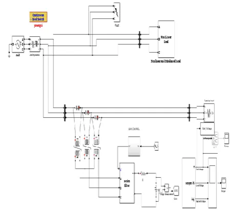
Fig 4 illustrates the representation of three phases DVR. The grid distributing 415 V, 50Hz, to the constant load and DVR is connected in series with the grid line with the help of injection transformer. The fault is created and examined how the DVR is operating while utility is under fault condition.
DVR contains converter which is used for power conversion and injection of voltage with the grid. Injection transformer is convenient for voltage injection at determined level towards the grid. In this work, different controllers P, PI and PID are used to reduce THD and maintain constant load voltage under sag and swell occurrence.
Fig.4: Simulink model of three phase DVR
Case 1: Using P-controller
[image:3.595.47.279.406.537.2]
Fig.5: a)Grid voltage, b)Load voltage and c)Injected voltage under Three Phase distortion.
Fig.6: THD for the load voltage under different harmonic order.
Case 2: Using PI-controller
In this work
,
the voltage sag is generated from t =0.05s to t=0.11s between two phases and swell rises from t=0.25s to 0.45s. In this condition, the three phase voltage across grid is shown in fig 7 a. It is found that two phases have low voltage and one phase have very low voltage from t=0.05s to t=0.11s during voltage sag and high voltage from t=0.25s to 0.45s during voltage swell, there is existence of switching frequency voltages in the converter, remaining switching time periods it maintains constant voltage. The three phase voltage across the load is shown in Fig 7 b and it is initiate that during occurrence of voltage sag and swell for particular switching period, it conserves constant load voltage because of using DVR. The injected voltage of DVR is shown in Fig 7 c. it is found that more voltage is injected or absorbed due topresence of voltage sag and swell. During voltage sag and swell conditions. DVR provides injected voltage and protects the system from distorted conditions. Fig 8 shows the THD for the load voltage under different harmonic order for the fundamental frequency (50Hz) and THD of load voltage are 4.24%.
Fig.7: a)Grid voltage, b)Load voltage and c)Injected voltage under Three Phase distortion.
Fig.8: THD for the load voltage under different harmonic order.
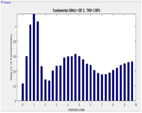
Case 3: Using PID-controller
and high voltage from t=0.25s to 0.45s during voltage swell, there is presence of switching frequency voltages in the converter, remaining switching time periods it maintains constant voltage. The three phase voltage across the load shown in Fig 9 b. it is initiate that during occurrence of voltage sag and swell for particular switching period, it preserves constant load voltage because of using DVR. The injected voltage of DVR is shown in Fig 9 c. it is found that during voltage sag condition, more voltages are injected. During voltage sag, DVR provides injected voltage and protects the system from distorted conditions. Fig 10 shows the THD for the load voltage under different harmonic order for the fundamental frequency (50Hz) and THD of load voltage are 3.95%.
Fig.9: a) Grid voltage, b) Load voltage and c) Injected voltage under Three Phase distortion.
Fig10: THD for the load voltage under different harmonic order.
s.no Name of the controller
T.H.D
1. P-controller 6.82%
2. PI-controller 4.24%
[image:5.595.326.528.49.135.2]3. PID-controller 3.95%
Table 1. Different types of controllers and their THD
[image:5.595.47.290.235.423.2]
Table 1 shows that the different types of controllers and their THD values. It is found that by using P, PI, and PID controllers, THD values of the system are found as 6.82%, 4.24% and 3.95% respectively. Among these controllers it is found that by using PID controller, the voltage across the load is constant and also lower THD value under fault condition.
VII. CONCLUSION
This paper dispenses the comparative evaluation of different types of controllers for improvement of power quality and mitigates the voltage distortions. The appropriate custom power devices are selected based on system configuration and type of load. It has been found that DVR has superior features such as vibrant reaction to disturbance, less cost and size. The new approach of control strategy such as SRF theory is discussed to improve the power quality using DVR. The whole performance of the DVR is inspected under faults. With this control strategy, the simulated output value of THD by using different controllers are illustrated i.e. P, PI, PID and it is found to be 6.82%, 4.24% and 3.95%. Among these controllers it is found that by using PID controller, the voltage across the load is constant and also lower THD value under fault condition. The voltage and current associated power quality problems are reduced by using DVR. Thus the DVR with PID controller obviously dispense the best economic solution for its expanse and capabilities under fault conditions.
ACKNOWLEDGMENT
The author would like to acknowledge and thanks to all respondents and Department of EEE, GMRIT (affiliated to JNTU KAKINADA) and Kalasalingam Academy of research and education for unconditional support.
REFERENCES
1.Xu, Q., Ma, F., Luo, A., He, Z. and Xiao, H. (2016). Analysis and control of M3C-based UPQC for power quality improvement in medium/high-voltage power grid. IEEE Transactions on Power Electronics, 31(12), 8182-8194.
2.Gupt, Satyaveer, et al. (2012). Custom power devices for power quality improvement: A review. International Journal of Research in Engineering & Applied Sciences, 2(2), 1646-1659.
3.Jothibasu, Suma, and Mahesh K. Mishra. (2014). A control scheme for storageless DVR based on characterization of voltage sags. IEEE transactions on power delivery, 29(5), 2261-2269.
[image:5.595.46.289.467.660.2]
5.Rauf, Abdul Mannan, and Vinod Khadkikar. (2015). An enhanced voltage sag compensation scheme for dynamic voltage restorer. IEEE Transactions on Industrial Electronics, 62(5), 2683-2692.
6.Saeed, Ahmed M., et al. (2016). Power conditioning using dynamic voltage restorers under different voltage sag types. Journal of advanced research, 7(1), 95-103.
7.Balamurugan, C. R., and K. Vijayalakshmi. (2018) Comparative Analysis of Various Z-source Based Five Level Cascaded H-bridge Multilevel Inverter. Bulletin of Electrical Engineering and Informatics, 7(1), 1-14.
8.Yi, Hao, Fang Zhuo, and Feng Wang. (2016). Analysis about overshoot peaks appearing in the current loop with resonant controller. IEEE Journal of Emerging and Selected Topics in Power Electronics, 4(1), 26-36.
9.Viet, D.T., Hieu, N.H., Le Hoa, N. and Khoa, N.M. (2015). A control strategy for dynamic voltage restorer. In Power Electronics and Drive Systems (PEDS), 11th International Conference on IEEE, 1106-1110.
10. Kohila, J., S. Kannan, and V. Suresh Kumar. (2015). Control of dynamic voltage restorer for injecting active power using synchronous reference frame theory. International Conference on Circuits, Power and Computing Technologies [ICCPCT-2015]. IEEE, 2015.
AUTHORS PROFILE
Srinivas Bugata was born in palakonda, Andhra Pradesh, India. He is received his B.Tech degree in Electrical and Electronics Engineering from Aditya institute of technology and management, Tekkali, affiliated to JNTUK University, India in 2013 and now he is pursuing his master’s degree in GMR institute of technology. His area of interest is Power Quality.
D. Danalakshmi was born in Chennai, Tamilnadu, India. She has received her B.E. degree in Electrical and Electronics Engineering from Thiagarajar College of Engineering, Madurai, affiliated to Madurai Kamaraj University, India in 2003 and M.E. degree in Power Systems Engineering from Thiagarajar College of Engineering, Madurai, affiliated to Anna University, Chennai, Tamil Nadu, India, in 2006. She has completed her Ph.D. degree in Kalasalingam University in September 2017. She has received the Advanced Mission 10X learning approach practitioners certificate and her assignments were made available in Wipro Mission 10X portal. She has been awarded with the appreciation certificate from Indian Institute of Technology, Kharagpur as topper for NPTEL online certification exam on "Power system" conducted on October 2017. She is a life member of Indian Society for Technical Education (ISTE). She has worked as an Assistant Professor in the Department of Electrical & Electronics Engineering, Kalasalingam University, Krishnankoil, Virudhunagar District, Tamil Nadu, India for eight years. Then, she has worked as an Assistant Professor in the Department of Electrical & Electronics Engineering, AAA college of Engineering and Technology, Amathur, Sivakasi, Tamil Nadu, India for two years. Then She worked in Madanapalle Institute of Technology. Presently, she is working as Associate Professor in the Department of Electrical & Electronics Engineering, GMR Institute of Technology, Andhra Pradesh. She has attended several International conferences and presented papers also. She is actively involved in research for the past five years. She is presently working in the area of Power System Optimization and Smart Grid.
V.Agnes Idhaya Selvi was born in Srivilliputhur, Tamil Nadu, India. She has received her M.E. degree in Power Systems Engineering from Annamalai University, Annamalai Nagar in 2004 and Ph.D. in 2017 from Kalasalingam Academy of Research and Education. She is a life member of Institute of Engineers, India, Indian Society for Technical Education (ISTE) and Graduate Student Member in IEEE. She has more than 12 years of teaching experience from 2004 onwards. She is presently working working as Assistant Professor in the department of Electrical & Electronics Engineering, Kalasalingam Academy of Research and