Abstract: Next generation networks are required to deliver extremely high data rates in order to enable mission critical services, massive IoT and enhanced mobile broadband. In the pursuit of high data rates, significant research is focused on higher frequency bands. mmWaves are the most promising carriers because of their associated bandwidth benefits. However, on the other hand, mmWaves also bring along difficulties in link management as the channel is totally different from the traditional systems. This paper evaluates the BER performance of mmWave-massive MIMO systems with Hybrid precoding and receiver beamforming. The availability of perfect CSI at both the transmitting and receiving ends of the downlink is assumed. The results demonstrate that BER performance at low SNR region remains almost exclusive of the system dimensions as long as CSI is available. It was observed that almost 20 dB SNR is required to achieve error performance of 10-5. Zero forcing and Wiener Filter precoder are also evaluated against each other with analog precoding and receiver beamforming.
Index Terms: mmWave, Massive MIMO, BER, Perfect CSI, Hybrid Precoding
I. INTRODUCTION
mmWave and Massive MIMO possess the most desirable characteristics for enabling future wireless networks. mmWave systems, because of the huge bandwidth dimensions have the potential to cater to some of the enhanced mobile broadband services envisioned for the fifth generation networks. Characteristics like high availability, reliability and deep coverage have to be attained for a promising candidacy in next-generation cellular so that mission critical services & services catering for Massive Internet of things can be supported by the same network. Thus, in addition to high bandwidth, communication links of very high quality need to be delivered. mmWaves have a very low wavelength and hence are not very well suited for long range communication directly. Powerful processing may, however, allow for wider cell radii. Massive MIMO systems, where the base station is equipped with large antenna arrays, improve the potential of mmWave carriers for 5G [1], [2]. Massive MIMO systems inherently come along with advantages like channel hardening & asymptotic orthogonality. A multitude of mobile equipment has to be served by a single Base station. This implies the multiplexing of data streams corresponding to different users. Traditional systems exploited baseband precoding for
Revised Manuscript Received on June 15, 2019.
Khushal Thakur, ECE department, Chandigarh University, Gharuan India
Bhasker Gupta, ECE Department, CCET, Chandigarh, India
Balwinder Singh Sohi, ECE department, Chandigarh University, Gharuan India
achieving multi user data transmission. The requirements of baseband precoder at mmWave are too difficult to achieve with the current state of the art technologies. Literature suggests the usage of Hybrid Precoding for such systems. A hybrid precoding system performs precoding in two stages, baseband and RF stage. The baseband precoding is in the digital domain while the RF precoding is in the analog domain.Analog precoding [3] involves controlling the phase of signals at transmitting antennas in order to direct beams in intended directions. Some of the IEEE 802.11 versions [4], [5] that operate on mmWaves make use of such analog beamforming. Analog beamforming however in itself is not sufficient because of its inherent constraints like availability of only quantized phase values & unavailability of adaptive gain control.Digital precoding in conjunction with such analog beamformers allows for improved performance management. Hybrid precoding algorithms with full CSI and partial CSI have been proposed in the literature. This paper shall assume the availability of Full CSI at both the transmitting and receiving end.
In subsequent sections, the following terminology is used: Capital Boldface Letters, e.g. Q, represents a matrix, small boldface letters, e.g. q represents a column vector, |Q| represents determinant of matrix Q, || Q ||F represents
Frobenius norm of Q, QT representstranspose of Q, Q* representsconjugate of Q, QH representsHermitian Transpose of Q, Q-1 representsinverse of Q&Q† representspseudo inverse of Q respectively.
II. SYSTEMMODEL
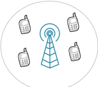
Consider a system model as depicted in figure 1 & 2. M mobile equipment users with ARX antennas each are served
by a single base station transmitting at a total average power of P with an array of ATX antennas. The antenna array has
AV vertical and AH horizontal antennas i.e. ATX = AV x AH.It
is further assumed that only one stream is assigned to a particular user & thus Ns = M. Also, it is assumed that at
max only one RF chain is assigned to a particularuser & so the number of RF chains, NRF ≥ M.All the mobile equipment
and the base station are assumed to operate in TDD mode with perfect synchronism.This paper shall focus only upon the downlink of the system with receiver beamforming into consideration.
BER Analysis of Hybrid Precoded Massive
MIMO Systems in Downlink with Receiver
Beamforming over mmwave Channels
In order to cater to the limited scattering exhibited by the mmWave channels, we assume a geometric channel model with L number of paths between a particular user and the base station. The geometrical channel can be transformed as
(1)
Where, represents the channel gain for lth path departing at angle & arriving at an angle . are antenna array response vectors at the Mobile equipment & the base station. As stated previously, a 2D array of antenna is being used at the Base station accordingly, the antenna array response vector can be defined as
(2)
[image:2.595.45.286.54.164.2]Where d & represent the antenna element separation & wavelength of the signal.
Figure 2 RF Beamforming Capable User Equipment
Let s = [s1, s2, s3, . . . ,sM]Trepresents a vector of symbols
being transmitted from the base station towards M users such that . si ϵ S represents the information
symbol desired by the ith user. These symbols go through two stages of precoding. A digital (baseband) precoder
followed byAnalog(RF)precoder
are applied by the base station.The transmit signal at the base station can be therefore expressed as
(3)
Let represent the signal received by the mth user, then
(4)
Let represent the combiner used at the mth receiving mobile equipment to process the received signal, then,
(5)
Where, I) represents the noise. Equation 5 can be rearranged as
(6)
Where, . The SINR observed by the mth
user can be given as
(7)
Table I Parameters used for simulation results of figure 5
Abbreviation Meaning
CSI Channel State Information
BER Bit Error Rate
SNR Signal to Noise Ratio
SINR Signal to Interference + Noise Ratio
MIMO Multi Input Multi output
RZF Regularized Zero Forcing
RF Radio Frequency
III. PRECODERDESIGN
We discuss some of the well-known precoders in this section and then conclude with precoder design for our system evaluation. A matched filter is known for its ease of implementation when compared to its complex counterparts that usually involve inversion of the channel matrix. The matched filter precoder tries to perform conjugate transpose of the channel matrix.
(8) A scaling factor is used to normalize the signal power, which ensures the same transmit power for all symbols. Eq. 8 can be modified for a Matched Filter precoded data stream as
(9) Matched filter precoding maximises the SNR at any intended user, and thus it is also called as Maximum Ratio Transmission (MRT) [6], [7]. The authors in [6] & [8] analyse the performance of MRT in the context of sum rate & total transmit power at the downlink. The work in [9] estimates the count of antennas as M= 81 & K=77 for an energy efficient system.
[image:2.595.53.285.426.561.2]Figure 3 Downlink with four single antenna user equipment
However, because of the close values of M & K, the asymptotic behaviour of massive MIMO is no longer valid. To summarize, MRT precoding performs optimally when the “number of antennas at the base station” is significantly larger than the “number of single antenna receivers”. While a matched filter delivers good performance in noise dominated systems, it is still inefficient for the systems where interference is significantly large than noise. One of the most interesting & widely appreciated precoding in interference dominating systems is the Zero Forcing precoding. The Zero Forcing precoding, as the name suggests, tries to nullify the signal transmission in the direction of unintended users, resulting in the removal of interference received at the intended user.The zero forcing precoder can be mathematically expressed as
(1 0) Eq. 10 can be modified for a Zero Forcing precoded data stream as
(11) The off-diagonal elements of depictcorrelation among the channel for different users. Channel capacity is reduced by ZF precoding when the channels are correlated [10]. The biggest weakness of ZF precoding is the well-known noise amplification. However, the ZF precoder serves optimally in the absence of noise. Regularized ZF precoder trades off the advantages of both MRT & ZF precoder. It is considered de facto standard for MIMO systems. A number of versions of RZF exist in literature. The RZF precoder can be mathematically expressed as [11]
(1 2) Eq. 12 can be modified for a Regularized Zero Forcing precoded data stream as
( 13) It is evident that eq. 12 converts into a ZF precoder for X=0 & λ=0. Also, a matched filter can be derived by setting X=0 & λ=∞. A new precoding scheme, Truncated Polynomial Expansiontries to implement the RZF precoding while reducing the complexity of implementation. The TPE precoder can be mathematically expressed as [12]
(14)
Wherewjis coefficient of precoder polynomial of order j.
Phased zero forcing [13] tries to implement a Hybrid precoding scheme, where the overall precoding matrix is derived as a multiplication of RF & baseband counterparts. In the RF part, only Phase control is used without causing any change in the magnitude of precoder. The phase is extracted from conjugate transpose of the channel. By aligning the phases of different channel elements, a huge gain can be achieved by virtue of the massive count of antennas. The analog precoding can be expressed mathematically as
(
15)
represents the phase corresponding to the element of the conjugate transposed channel at a location (i, j). Thus, the overall channel H now becomes
(
16)
The PZF is then implemented as
[image:3.595.83.242.49.189.2]
( 17) Where is a diagonal matrix for power normalization Precoding algorithm selected in this paper for BER analysis is as given below
Figure 4 Flow of ZF based Hybrid Precoded system
IV. PERFORMANCEANALYSIS
For QPSK signalling with Gray-mapped symbols, the probability of error can be expressed for mth user as
(18)
Table II Parameters used for simulation results of figure 5
Parameter Value
ATX 64 (8 x 8 UPA)
ARX 16 (4 x 4 UPA)
M 4
Modulation {'QPSK','8PSK','16QAM','64QAM' }
SNR -20:3:20
L 1
Monte-Carlo simulations
1e4
BER performance is evaluated for the system explained
previously, through
[image:3.595.311.533.360.485.2]availability of perfect CSI at both the Base station and the user equipment. This allows for setting the array response vector aTX&aRXas the analog precoder matrices at the base
station and the user equipment respectively. Also, the two precoders only have phase
value matrices & thus have
a. ATX = 64, ARX = {1,4,16,64}, {QPSK} b. ATX = {4,16,64}, ARX = 1, {QPSK}
c. ATX = 64, ARX = {1,4,16,64}, {16QAM} d. ATX = {4,16,64}, ARX = 1, {16QAM}
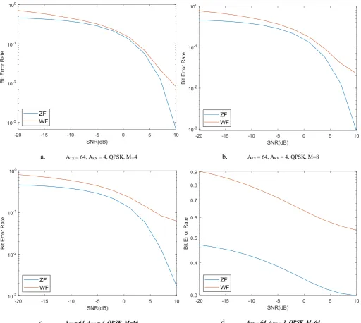
a. ATX = 64, ARX = 4, QPSK, M=4
c. ATX = 64, ARX = 4, QPSK, M=16
no impact over the magnitude of the signals involved.From figure 5 it is clear that the count of antennas at either side has a very limited impact over the BER performance in the case when full CSI is available at the Base station and the Mobile equipment as well. The BER performance follows the expected nature as we move along the order of modulation. Figure 6 compares BER performance of Wiener Filter & Zero Forcing precoder, again with an assumption of availability of CSI at both the transmitting and receiving ends of the downlink. The performance gap keeps on increasing as the number of users increases. Figure 6a, 6b, 6c assume 64 Antennas equipped at the base station and 4 antennas equipped at every single mobile equipment. The number of mobile users/ equipment varies as 4, 8, 16 for figure 6a, 6b & 6crespectively, while keeping the same system configuration. Figure 6d assumes 64 single antenna mobile equipment. The performance of both the precoders falls severely in this case becausethe advantages put in by the “massive” nature of BS antennas are lost. Thus, irrespective of count of antennas at the base station, if the number of users to be served is the same as thecount of antennas at the base station, the precoders shall behave very
b. ATX = 64, ARX = 4, QPSK, M=8
d. ATX = 64, ARX = 1, QPSK, M=64
poorly. This implies that the scalability of such systems with increasing users while sustaining the advantages of massive MIMO becomes challenging and needs to be addressed.
V. CONCLUSION
Most of the available literature is focused over capacity and rate related parameters but there is a need to ensure BER performance of the next generation systems as well. This becomes even more important because of the constraints put in by the nature of mm Waves. Hybrid precoding along with receiver combining was explored for a variety of system configurations in this paper. It was found that when perfect CSI is available at both the transmitting and receiving ends, processing playsa more vital role than diversity.ZF & WF precoding were evaluated for BER in systems with receiver combining and they performed as very closely especially in the low SNR range till 5 dB.
Both exhibit poor
[image:5.595.14.527.49.507.2]however, zero forcing precoder out performs WF precoding as SNR improves. In the case when number of antennas at base station served equal count of users, unacceptable error performance was observed even at high SNRs. The entire work presented in this paper assumes full CSI at both base station and mobile equipment. This however is very difficult to achieve in mm Wave systems. Thus, performance needs to be evaluated against different systems in which imperfect CSI is available or not available at all [14], [15]. New precoding solutions that deliver a minimum BER performance while not putting too much load of feedback on system need to be delivered. Precoding solutions targeting better BER, improved sum rates & at the same time reduced complexity should be targeted in future. Induction of OFDM & exploration of related problems[16-18] will be interesting in massive MIMO systems.
REFERENCES
1. O. El Ayach, S. Rajagopal, S. Abu-Surra, Z. Pi, and R. Heath, “Spatially sparse precoding in millimeter wave MIMO systems,” IEEE Trans. Wireless Commun., vol. 13, no. 3, Mar. 2014, pp. 1499–1513. 2. T. Rappaport et al., “Millimeter wave mobile communications for 5G
cellular: It will work!” IEEE Access, vol. 1, May 2013, pp. 335–349. 3. S. Hur et al., “Millimeter wave beamforming for wireless backhaul and
access in small cell networks,” IEEE Trans. Commun., vol. 61, no. 10, Oct. 2013, pp. 4391–4403.
4. T. Nitsche et al., “IEEE 802.11ad: Directional 60 GHz communication for multi-Gigabit-per-second Wi-F,” IEEE Commun. Mag., vol. 52, no. 12, Dec. 2014, pp. 132–141.
5. T. Baykas et al., “IEEE 802.15.3c: The first IEEE wireless standard for data rates over 1 Gb/s,” IEEE Commun. Mag., vol. 49, no. 7, Jul. 2011, pp. 114–121.
6. T. Parfait, Y. Kuang, and K. Jerry, “Performance analysis and comparison of ZF and MRT based downlink massive MIMO systems,” in Proc. 6th Int. Conf. Ubiquitous Future Netw., Shanghai, China, 2014, pp. 383–388.
7. A. Kammoun, A. Muller, E. Bjornson, and M. Debbah, “Linear precoding based on polynomial expansion: Large-scale multi-cell MIMO systems,” IEEE J. Sel. Topics Signal Process., vol. 8, no. 5, pp. 861–875
8. V. P. Selvan, M. S. Iqbal, and H. S. Al-Raweshidy, “Performance analysis of linear precoding schemes for very large multi-user MIMO downlink system,” in Proc. 4th Int. Conf. Innov. Comput. Technol., Luton, U.K., 2014, pp. 219–224.
9. E. Bjornson, L. Sanguinetti, J. Hoydis, and M. Debbah, “Optimal design of energy-efficient multi-user MIMO systems: Is massive MIMO the answer?” IEEE Trans. Wireless Commun., vol. 14, no. 3, Mar. 2015, pp. 3059–3075
10. X. Gao, O. Edfors, F. Rusek, and F. Tufvesson, “Linear pre-coding performance in measured very-large MIMO channels,” inProc. 2011 IEEE Veh. Technol. Conf., San Francisco, CA, USA, 2011, pp. 1–5. 11. J. Hoydis, S. Brink, and M. Debbah, “Massive MIMO in the UL/DL of
cellular networks: How many antennas do we need?” IEEE J. Sel. Areas Commun., vol. 31, no. 2, Feb. 2013, pp. 160–171.
12. A. Muller, A. Kammoun, E. Bjornson, and M. Debbah, “Linear precoding based on polynomial expansion: Reducing complexity in massive MIMO,” EURASIP J. Wireless Commun. Netw., vol. 2016, 2016, Art. no. 63.
13. L. Liang, W. Xu, and X. Dong, “Low-complexity hybrid precoding in massive multiuser MIMO systems,” IEEE Wireless Commun. Lett., vol. 3, no. 6, Dec. 2014, pp. 653–656.
14. A. Alkhateeb, G. Leus and R. W. Heath, "Limited Feedback Hybrid Precoding for Multi-User Millimeter Wave Systems," in IEEE Transactions on Wireless Communications, vol. 14, no. 11, Nov. 2015, pp. 6481-6494
15. S. Jacobsson, G. Durisi, M. Coldrey, T. Goldstein and C. Studer, "Quantized Precoding for Massive MU-MIMO," in IEEE Transactions on Communications, vol. 65, no. 11, Nov. 2017, pp. 4670-4684. 16. P. Kashyap and K. Thakur, "Improved ACE method for reducing
PAPR in OFDM system," 2018 Second International Conference on Inventive Communication and Computational Technologies (ICICCT), Coimbatore, 2018, pp. 402-406.
17. S. Sharma and K. Thakur, "Carrier frequency offset in OFDM systems," 2018 2nd International Conference on Inventive Systems and Control (ICISC), Coimbatore, 2018, pp. 369-373.
18. S. Sharma and K. Thakur, "Improved CE-OFDM Using LDPC Codes for Frequency Offset Compensation," 2018 2nd International Conference on Trends in Electronics and Informatics (ICOEI), Tirunelveli, 2018, pp. 869-873
Khushal Thakur is a PhD student at Chandigarh University. His areas of interest are mmWaves, Massive MIMO & Sensor Networks. He has more than four patents to his name & has published a book on mmWaves.
Dr. Bhasker Gupta is an associate professor at CCET, Chandigarh. He has published research in many reputed journals & conferences. His fields of interest include MIMO OFDM systems.
![Figure 2 RF Beamforming Capable User Equipment s = [s, s, s, . . . ,s]Trepresents a vector of symbols](https://thumb-us.123doks.com/thumbv2/123dok_us/8192689.258439/2.595.53.285.426.561/figure-beamforming-capable-user-equipment-trepresents-vector-symbols.webp)