Abstract: HSS (Hollow Structural Steel) tubular members used in buildings and bridges for structural application is rapidly developing technique in the recent era. Since, they have many advantages over RC structural members. This paper presents the application of CFRP on HSS tubular members under axial compression. Typical failure occurred during axial loading was local buckling, and this could be reduced by wrapping CFRP sheets around the HSS tubular columns were investigated experimentally. Eight steel samples are used in this test. Among eight specimens, two are unwrapped and the remaining six columns are externally wrapped by CFRP. CFRP sheets are used as strips, and the width of the sheets are constant. The spacing between the CFRP sheets is also constant. All columns are tested in column tester till the maximum to understand their failure modes, Ultimate load, load Vs. Displacement, Stress- Strain behaviour and Ductility index. Finally, results obtained from the experimental investigation could be validated with ANSYS software. The ultimate load and displacements from ANSYS validation are closely match with test results.
Keywords: Axial compression, Wrapping, CFRP sheets, Buckling, HSS columns, Short columns, Strips and ANSYS.
I.INTRODUCTION
HSS (Hollow Square Steel) tubular members used for structural application increased wide range both onshore and offshore structures. They have many adantages over traditionally available RC framed constructional methods including high strength and ductility properties. SHS members usually fails by local buckling due to excees axial compressive loads and corrosion in severe enuironmental condition. Traditional strengthening methods like plate bonding methods do not satisfy the needs when they subjected by further corrosionand excess loading. Also further repeat of this proceedure was not an ideal solution for the structure because of excess stress concentration during welding and high cost. Structural engineers search for a alternate solution with minimum cost and long losting new strengthening techniqe without any conflict. Strengthening using FRP (Fibre Reinforced Polimer) composites do not have any demerits like plate bonding because they had variety of advantages like high strength to weight ratio, high environmental durability and cover more areas with minimum period of time. Moreover, skilled labuors required for this operation is very less. Several RC structures like buildings and bridges are successfully strengthened using FRP composites during the mid 80’s till the recent decades. Many of the researchers were used FRP copmposites for their research in strengthening of
Revised Manuscript Received on August 05, 2019.
Dr. S. Sivasankar*, Associate Professor, Department of Civil Engineering, CMR Technical Campus, Hyderabad, Telangana, INDIA.
Dr. A. Praveen Kumar, Associate Professor, Department of Mechanical Engineering, CMR Technical Campus, Hyderabad, Telangana, INDIA.
beams, collumns and slabs. Studies conducted by [1 and 2], shows that the Reinforced Concrete beams externally reinforced by fibre sheets enhanced the loadcarrying capacity significantly. Numerous studies have done on the use fibre sheets for the restoration of RC members [3 and 4]. Some of the experimental studies reporting the compressive behaviour of RC columns externally confined by CFRP sheets [5 and 6]. The reported studies have shown that the RC meembers strengthened and repaired with FRP sheets can be effectively incresed the strength and ductility.
Zhong Tao & Lin-Hai Han [7] reported the strength improvement of fire affected concrete filled steel member repaired by fibre sheets. Teng & Hu [8] conducted an experiment on hollow circular tubes strengthened by GFRP sheets. It was found that, GFRP wrapped specimens showed high strength and ductility compared to bare specimen. Haedir et al [9] discussed the response of fibre sheets on steel structures. Ehab Ellobody [10] studied the strength and stiffness properties of concrete-filled stainless steel specimen confined by FRP sheets. Keykha et al [11] conducted both experimental and analytical study on hollow specimen externally reinforced with FRP sheets. Sivasankar.S et al [12] described the effectiveness of CFRP sheets on steel columns experimentally. Research articles explained above was not given clear idea about the optimum usage of CFRP sheets. This research article presents the SHS tubular columns externally confined by CFRP strips in transverse direction. Finally an analytical model was developed using ANSYS to validate the test results.
II.TEST PROGRAMME
Eight columns were investigated. Two columns are control and the remaining six were wrapped by CFRP sheets. Width and distance between CFRP strips are kept constant and the number of layers are varied like one, two and three. Width and distance are kept 50 mm and 40 mm respectively. Unwrapped columns are named CC1 and CC2 wereas the wrapped columns were named HS-50-40-T1, HS-50-40-T2 and HS-50-40-T3 respectively. HS referred as horizontal strips, 50 represents width of CFRP, 40 represents the spacing between the layers and T1 represented the number of layers wraped in transverse direction.
A. Carbon Fibre and Resin
Carbon fibre MBrace 240 was used in this test. Tensile strength of CFRP is 3800 N/mm2. The thickness of the fibre is 0.234 mm. Resin and hardener named MBrace saturant was used for this test. Mixing ratio is 100:40.
Numerical Modeling of Square Steel Members
Wrapped by CFRP Composites
B. Square Hollow Steel Tube
The dimension of the specimen is square 91.5 mm×91.5 mm. All specimens are 600 mm height and 3.6 mm thickness. Average yield strength found by coupon tests is 342 Mpa. Selection of hollow steel members based on the code IS 4923 -1997.
C. Test Specimen Preparation
After cut the specimen into the required length all columns are ready for the surface grinding to achieve perfect bonding and this can be done by sand blasting. Columns after sand blasting was shown in figure 1. Surface of the samples were washed by acetone before commencement of wrapping. Resin and hardner were mixed thoroughly by hand mix five minutes before the wrapping. Initially apply a layer of resin coating directly on the column surface by using wire brush. Before wrapping the first layer of CFRP strips, a GFRP surface mat was wrapped arround the column throughout its height to prevent the galanic corrosion. Another layer of resin coating was applied over GFRP sheets.. After this, single CFRP layer is wrapped transversely arrond the column. Steel ribbed roller was used to eliminate the gap present in between CFRP layers. The same proceedure was continued for the second and third layers of CFRP wrapping. Columns after CFRP wrapping proceedure was shown in the figure 2. After the successful completion CFRP wrapping all wrapped columns are dryed in room temperature for curing for a period of one week.
[image:2.595.59.258.371.551.2]Fig. 1. Column after sandblasting
Fig. 2. Columns after CFRP wrapping
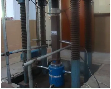
D. Testing
After curing period is over all columns are ready for axial compression test. This test is done on a 150 tonnes capacity column tester machine. To measure the displacements, two LVDTs were mounted on test specimen which is represented in figure. 4. One LVDT was mounted on the column base in vertical position and the other one is mounted along the height of the column. Load and the corresponding deformation values are displayed in the data logger. 1000 kN Capacity laoad cell was used for applying the load. All columns are tested in column testing machine until the ultimate load and fibre rupture.
III.EXPERIMENTAL RESULTS AND DISCUSSION
A. Failure Mode
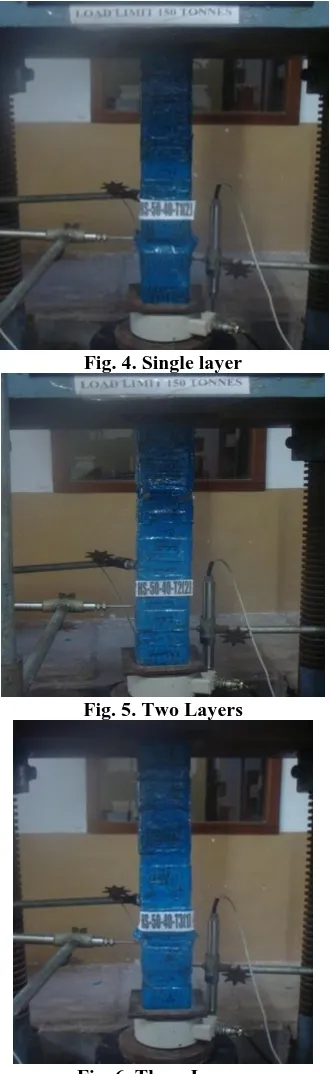
[image:2.595.60.262.382.741.2]Fig. 3- 6 shows the failure patterns of bare column and columns wrapped by CFRP sheets. Bare (CC2) column failed in typical local buckling which is occurs at the bottom similar to that of elephant foot buckling [Teng and Hu]. Specimen wrapped with single layer, failure takes place just above the bottom which is shown in Fig. 4. Fibre rupture occures with a huge sound after the column reached the maximum. Subsequently a huge reduction, because fibre activation is completely vanished. Figure 5 represented the failure pattern of column wrapped by two sheets. In this column buckling takes place on 200 mm from the top. Failure is similar to HS-50-40-T1, however the axial load increased more compared to that of column wrapped with single layer. Specimen wrapped by three layers (HS-50-40-T3) shown in figure 6, exhibited similar kind of failure occurs as in the case of single layer, but the load carried by the column is higher that of column wrapped with single and double layers respectively. All columns wrpped by CFRP sheets, failure was purely fibre rupture and not by delamination. This results ensures the perfect bonding of CFRP with steel columns.
[image:2.595.339.517.471.615.2] [image:2.595.69.267.556.765.2]Fig. 4. Single layer
Fig. 5. Two Layers
Fig. 6. Three Layers
B. Ultimate Strength
Ultimate strength of CFRP wrapped specimen and unwrapped samples are presented in Fig 7. Figure clearly showed that, CFRP wrapped sample have higher ultimate load compared to unwrapped columns. Specimen HS-50-40-T1, the ultimate strength is 677 kN and the percentage increment compared to CC2 is 19.82%. In case of HS-50-40-T2, ultimate load value was 685 kN which is 21.24% higher compared to CC2. The increase rate was not exactly the doble as compared to column wrapped by single layer. Because the resin breakage between the CFRP layers. Similar to single layer and two layers, the ultimate strength of three layers were increased and the corresponding ultimate load is 690 kN and the percentage increment compared to CC2 sample is
22.12%. Above results cleary showed the increment of strength by adding more layers.
[image:3.595.309.542.74.264.2]
Fig.7. Ultimate Load Capacity Curve
C. Axial Stress Strain Behaiour
Figure 8represented the axial stress –strain curve for columns wrapped with CFRP and unwrapped columns. CC2 specimen expressess an exact variation similar to ordinary steel. Specimens wrapped with CFRP strips exhibited an linear variation until reach the CC2 failure after that there was a non linear variation till the failure load. This is because of the better confinement proided by the addition of number of layers. Once the specimen reached the ultimateload a huge drop shown in the stress-strain curve because of fibre rupture and no longer the CFRP strips withstand the load.
0 100 200 300 400 500 600 700
0 0.01 0.02 0.03
Axial strain
A
xi
al
s
tr
es
s
(N
/mm
2 )
[image:3.595.311.544.451.636.2]C C 2 HS -50-40-T1 HS -50-40-T2 HS -50-40-T3
Fig. 8. Stress Strain Curve D. Ductility Index
Fig. 9. Ductility Index Curve
IV.ANSYS MODELLING
FRP is modelled using solid eight node element shell 181. The SHELL181 element has 4 nodes and linear interpolations are used within the element. Beam 188 was used for the fibre element. SHELL 181 and LINK8 are used for the attachment of FRP and steel. Figure 10 represents the load and boundary settings of the specimen.
[image:4.595.65.292.46.222.2]A. Failure mode
[image:4.595.322.530.49.445.2]Fig. 10. Loading and boundary condition
Fig. 11. Failure mode of CC2
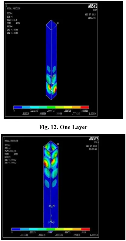
Fig. 12. One Layer
[image:4.595.60.277.348.538.2]Fig. 13. Two Layers
Fig. 14. Three Layers
Figure 11-14 represented the failure mode of CC2 and CFRP wrapped columns obtained from the ANSYS modelling. Failure mode of columns CC2 and wrapped columns both obtained from ANSYS modelling and experimental programme were similar. Ultimate load obtained by ANSYS
modelling for CC2 and
specimens wrapped CFRP
[image:4.595.322.530.466.684.2] [image:4.595.65.272.560.752.2]Table 1. From Table 1, it was observed that the percentage error for specimens CC2 and wrapped columns were found to be very less. and there will be a much closer value with the experimental results.
Table- I: Comparison between Experiment Vs ANSYS Modeling
Sl.No Specimen
Details
Ultimate Load (kN)
Percentage Error
Experiment ANSYS
Model
1 CC2 565 564.7 0.053
2 HS-50-40-T1 677 675.8 0.17
3 HS-50-40-T2 685 682.1 0.423
4 HS-50-40-T3 690 688.2 0.260
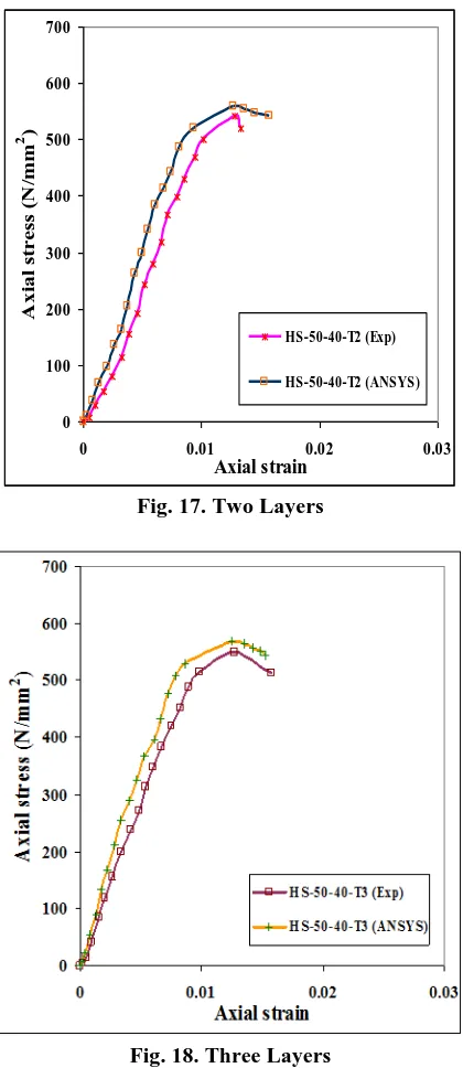
B. Stress-strain behavior
InFigure 15-18the stress-strain behaviour of CC2 and CFRP wrapped columns obtained from the ANSYS modelling and experimental investigation was presented. From this figures, it can be seen that all confined and unwrapped columns have shown a similar variation at the initial stage and a huge variation after control column peak load until CFRP rupture. Compression strain values are obtained from ANSYS shown the closed result with the test results.
0 100 200 300 400 500
0 0.01 0.02 0.03
Axial strain
A
xi
al
s
tr
es
s
(N
/mm
2 )
C C 2 (Exp)
[image:5.595.324.530.56.295.2]C C 2 (ANSYS)
Fig. 15. CC2
0 100 200 300 400 500 600 700
0 0.01 0.02 0.03
Axial strain
A
xi
al
s
tr
es
s
(N
/mm
2 )
HS-50-40-T1 (Exp)
HS-50-40-T1 (ANSYS)
Fig. 16. One Layer
0 100 200 300 400 500 600 700
0 0.01 0.02 0.03
Axial strain
A
xi
al
s
tr
e
ss
(
N
/mm
2 )
HS-50-40-T2 (Exp)
HS-50-40-T2 (ANSYS)
Fig. 17. Two Layers
Fig. 18. Three Layers
V.CONCLUSION
From the above experimental investigation and ANSYS modelling done on SHS tubular columns the following conclusions were made:
All columns failed by local buckling only and not by yielding of steel tubes.
Columns wrapped with CFRP strips, failure occurred at the peak load due to fibre rupture and no delamination take place.
Compared to CC2, columns wrapped with CFRP strips showed higher ultimate load. Among the confined columns, column wrapped with three strips showed better strength. Ultimate load of specimens wrapped with one, two and three layers showed 19.82%,
[image:5.595.51.281.104.209.2] [image:5.595.64.282.304.718.2]compared to CC2 respectively.
All columns wrapped by CFRP strips exhibited linear variation till reached the control column peak load and thereafter a huge variation shown in the curve due to the CFRP activation.
Ductility Index value for columns wrapped with CFRP strips was higher compared to CC2.
Results obtained from the ANSYS modelling showed a very much closed results with the experimental results.
REFERENCES
1. Arduini, M., Nanni, A., 1997. Behavior of Precracked RC beams strengthened with carbon FRP Sheets. ASCE Journal of for Composites Construction 1 (2), 63–70.
2. Chajes, M.J., Thomson, T.A., Januszka, T.F., Fin, W., 1994. Flexural strengthening of concrete beams using externally bonded composite materials. Construction and Building Materials 8 (3), 191–201. 3. Bonacci, J.F., Maalej, M., 2000. Externally bonded fiber-reinforced
polymer for rehabilitation of corrosion damaged concrete beams. ACI Structural Journal 97 (5), 703–711.
4. Teng JG, Lam L, Chan W, Wang J. Retrofitting of deficient RC cantilever slabs using GFRP strips. J Comput Constr L 2000; 4(2): 75–84.
5. Xiao Y, Wu H. Compressive behavior of concrete confined by carbon fiber composite jackets. Journal of Materials in Civil Engineering 2000; 12(2).
6. Li, J & Hadi, MNS 2003, ‘Behaviour of externally confined high-strength concrete columns under eccentric loading’, Composite Structures, vol. 62, pp. 145-153.
7. Zhong Tao, Lin-Hai Han & Ling-Ling Wang 2007, ‘Compressive and flexural behaviour of CFRP-repaired concrete-filled steel tubes after exposure to fire’, Journal of Constructional Steel Research, vol. 63, pp. 1116-1126.
8. Teng, JG & Hu, YM 2007, ‘Behaviour of FRP-Jacketed circular steel tubes and cylindrical shells under axial compression’, Construction and Building Materials, vol. 21, pp. 827-838.
9. Haedir, J, Bambach, MR, Zhao, XL & Grzebieta, RH 2010, ‘Analysis of CFRP externally-reinforced steel CHS tubular beams’, Composite Structures, vol. 92, pp. 2992-3001.
10. Ehab Ellobody, 2013, ‘Numerical modelling of fibre reinforced concrete-filled stainless steel tubular columns’, Thin-Walled Structures, vol. 63, pp. 1-12.
11. A.H. Keykha, M. Nekooei, R. Rahgozar, Numerical and experimental investigation of hollow steel columns strengthened with carbon fiber reinforced polymer, Journal of Structural and Construction Engineering, 3 (1) (2016) 49-58.
12. Sundarraja, MC & Sivasankar, S 2012, ‘Axial behaviour of HSS tubular sections strengthened by CFRP strips- An experimental investigation’, Science and Engineering of Composite Materials. vol. 19, pp. 159-168.
AUTHORSPROFILE
Dr. S. Sivasankar is presently working as an Associate professor in the Department of Civil Engineering, CMR Technical Campus, Hyderabad, Telangana. He has eight years of teaching experience and one year industry experience. Also he has four years of research experience. He published ten research articles in national and international journals. His research area includes steel-concrete composites, strengthening and retrofitting of steel and concrete structures and corrosion assessment in steel and concrete. He is a life member in ISTE, IAE and IE chapters.
Dr. A. Praveen Kumar is presently working as an Associate Professor in the Department of Mechanical Engineering, CMR Technical Campus, (A Unit of CMR Group of Institutions) Hyderabad, Telangana. He acquired distinction in