profusion. A Boost Converter with a high gain can be one solution towards to obtain the maximum efficiency. A comparative analysis is done between SEPIC and KY Boost Converter (KYBC) to identify the best converter with maximum efficiency using MATLAB Simulation. The Voltage conversion ratio is high for KYBC and also suited for low power applications. The simulation results also reveal that the KYBC is best suited in terms of high gain and less voltage and current ripple.
Keywords: Renewable Energy, SEPIC Converter, KY Boost Converter (KYBC)
I.INTRODUCTION
Renewable Energy plays a vital role in today’s power generation and also leads to Distributed Generation, Micro-grid and Smart cities. Researchers have been constantly working on the Converters to obtain better voltage gain and efficiency with reduced ripple in both voltage and current [1]. A converter is an electric power converter that changes the voltage or current of an electrical power source. DC-to-DC converters are electromechanical device that converts the dc voltage from one value to another value. Renewable Energy Systems requires a high gain boost converters for most of the applications. This could be effectively done implementing the boost converter [2]-[3]. The major drawback of the converter is the pulsating output currents, which tend to cause a large ripple in the output voltage. The ripples in the output can be reduced by implementing the converter with the interleaved concept. SEPIC converter finds its applications in SMPS and in high quality input power requirements [4]-[7].
A new converter named KY converter derives its name from its founder K. I. Hwu and Y. T. Yau [7]. The KY converter is a step up DC-DC converter with transient response operating in CCM always with low voltage ripple, non-pulsating current and the KY converter provides a larger voltage gain than the conventional boost converter[8].To overcome the drawbacks in Boost Converter, aKY converter along with synchronous rectified boost converter is used[9].And the other way is to use the capacitor with large capacitance and low equivalent series resistance (ESR), is to add an LC filter, and the other way is to increase the switching frequency [10]-[13].
Revised Manuscript Received on May 22, 2019.
Gayathri Devi Ramaraj, Assistant Professor, Sri Sairam Engineering College, Chennai
Booma Nagarajan, Professor, Jerusalem College of Engineering, Chennai
level of the application increases, the switch has to block more voltage during the turn off process which further increases the switching losses, thereby resulting in poor efficiency. The switching losses can be nullified through Zero Voltage Switching (ZVS) or Zero Current Switching (ZCS) or combination of both, popularly known as soft switching techniques. Researchers have been working on the different converters topologies comparison [14]-[18]. This paper compares the SEPIC converter and KYBC with respect to parameters such as high voltage gain, reduced voltage and current ripple through simulations under the conditions of identical input voltage, frequency and duty cycle using MATLAB/Simulink.
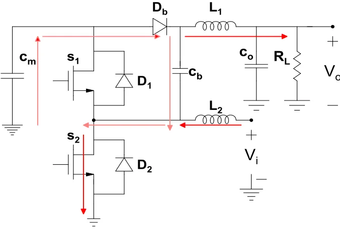
II. MODES OF OPERATION OF KY BOOST CONVERTER
Fig. 1 KY Boost Converter Mode 1
In this mode of operation, switch S1 remains off and S2 remains on. The diode Db gets forward biased as the capacitor Cb is connected to ground through its’ negative terminal. It is evident from the circuit, that in this mode of operation, the capacitor Cm discharges and Cb charges. Magnetizing current flows through L1 and demagnetizing current flows through
L2since the voltage across L1 is the input voltage Vi and the voltage across L2 is the output voltage Vo The difference between the current in the inductor L1 and load (RL) current flows through the capacitor Co. The sum of the capacitor current ICb and the current in the inductor IL2 flows through the capacitor Cm.
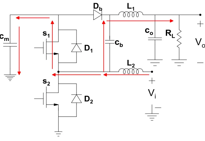
[image:2.612.137.475.435.666.2]Fig. 3 MODE 2 -KY Boost Converter
---6
---7
---8
---9
---10
III. SEPIC CONVERTER
Another kind of dc-dc converter that has the capability of providing buck-boost operation while maintaining the same polarity of output voltage as that of input is SEPIC converter (Single ended primary inductance convertor). It is a modification of basic boost and cuk convertor but the main drawback of cuk convertor is that it inverts the voltage. SEPIC has an advantage of providing non-inverted output voltage (as same that of input) by series coupling capacitor. It is superior to other convertors in terms of its switching losses, ripple, transient time and output noise. It consists of two inductors and a coupling capacitor for providing positive regulated DC
voltage which can be less (buck operation) or more (boost operation) than the input voltage. It can operate in the buck mode or the boost mode by appropriately controlling the duty ratio of the controllable switch, for example, transistor. The output voltage can be increased by increasing the turn on time of the controllable switch (since the duty ratio is increases). The greater the percentage of duty cycle, greater will be inductor charging which increases the output voltage [10]. Basic Operation
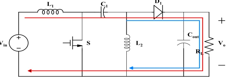
Fig. 4 SEPIC Converter Turn ON Process
Once the gate pulse is provided, MOSFET (S) turns on, the coupling capacitor discharges through the inductor L2. The inductor L2gets charged by the coupling capacitor and the
[image:4.612.117.498.288.428.2]inductor L1 gets charged by input voltage. Diode D1 is reverse biased. The output is maintained by output capacitor ( = ). Fig 2 shows Turn ON process of sepic
Fig. 5 Turn ON process Turn OFF Process
Once the gate pulse is removed, MOSFET (S) turns off, the charged inductor L1provides energy (discharges) to the load through the diode and charges the output capacitor. The output
voltage is maintained across L2 ( = ) .Both coupling and output capacitor gets recharged to provide load current and charge inductor L2 when S is ON. Here fig 3 shows the turn OFF process of sepic convertor
[image:4.612.127.489.528.656.2]
Ripple Current = *40% = *40%---15
Ripple Voltage = 1% of ---16
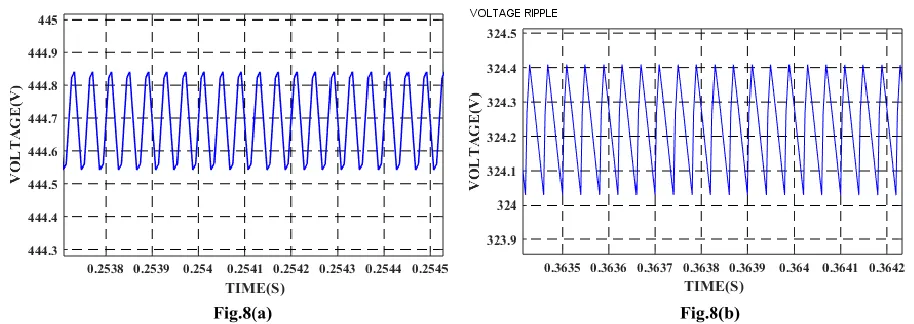
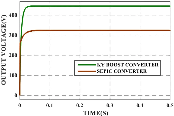
[image:5.612.314.564.50.161.2]Both the SEPIC Converter and KYBC are validated through the simulations using MATLAB/Simulink with the input voltage of 150V, frequency f= 25 kHz and a duty cycle of 50% for both the converters. The simulated waveforms of output voltage, voltage ripple and current ripple are shown in Fig.7, Fig.8 and Fig.9 respectively.
Fig. 7 Output Voltage waveform of (a) KYBC (b) SEPIC Converter
[image:5.612.74.531.471.633.2]Fig. 9 Current Ripple (a) KYBC (b) SEPIC Converter
Fig. 8 and 9, shows the voltage ripple and current ripple of both the converters from which it’s identified that the ripple of KYBC is lesser compared to that of the SEPIC.
Fig. 10 Comparison Waveform of KYBC and SEPIC Converter By comparing Fig.7 and Fig.10, it can be concluded that the
load (output) voltage of KYBC is higher compared to that of SEPIC which leads to high gain for the same value of input voltage. Also both current ripple and voltage ripple gets reduced in KY Boost converter.
Table. 1 Comparison of Parameters from Waveforms of KYBC and SEPIC Converter
PARAMETERS SEPIC
CONVERTER
KY BOOST
CONVERTER OUTPUT
VOLTAGE(V)
324 444
GAIN 2.16 2.96
VOLTAGE RIPPLE (V)
0.3798 0.2524
CURRENT RIPPLE (A)
0.0038 0.0033
performance in terms of higher output voltage as well as the reduction in both the current and voltage ripples.
V. CONCLUSION
[image:6.612.154.443.279.471.2]6. 2. Dr. Ridly, Ray. “Analyzing the Sepic Converter” 2006, Ridley Engineering. March 2014.
7. K. I. Hwu and Y. T. Yau, “KY converter and its derivatives,” IEEE Trans.Power Electron., vol. 24, no. 1, pp. 128–137, Jul. 2009.
8. Meera R Nair, Ms. Priya Jose, “ Voltage Gain Enhancement Using Ky Converter”,IOSR Journal of Electrical and Electronics Engineering (IOSR-JEEE) e-ISSN: 2278-1676,p-ISSN: 2320-3331, PP 27-34
9. K. I. Hwu, Member, IEEE, and Y. T. Yau, Student Member, IEEE,” A KY Boost Converter”,VOL. 25, NO. 11, NOVEMBER 2010.
10. F. L. Luo and H. Ye, “Positive output super-lift converters,” IEEE Trans. Power Electron., vol. 18, no. 1, pp. 105–113, Jan. 2003.
11. K.I.Hwuand , Y.T.Yau,“SoftswitchingofKYconverter,”inProc.IEEE APEC Conf., 2008, pp. 1477–1482.
12. Jiteash kumar V, Kirubhakaran U,Karthikeyan G, Essaki Raj R,” KY CONVERTER FOR RENEWABLEENERGY SYSTEMS”, International Journal of Pure and Applied Mathematics, Volume 118 No. 24 2018 13. S. Karthikumar,N. Mahendran, “Neuro Fuzzy Controller for Positive
Output KY Boost Converter to Reduce Output Voltage Ripple,ELEKTRONIKA IR ELEKTROTECHNIKA, ISSN 1392-1215, VOL. 19, NO. 8, 2013.
14. Hwu,K.I.;Jiang,W.Z.2013 “Applying Couple inductor to step-up Converter Combining KY and Buck-Boost Converters, IEEE 10th International Conference on Power Electronics and Drives System, 2013. 15. M.L. Bharathi, “Comparison of Solar Powerd SEPIC, ZETA and ILBC
Converters Fed DC Drive”Indian Journal of Science and Technology, Vol 8(S7), 247–250, April 2015.
16. S. Karthikumar,N. Mahendran, “Neuro Fuzzy Controller for Positive Output KY Boost Converter to Reduce Output Voltage Ripple,ELEKTRONIKA IR ELEKTROTECHNIKA, ISSN 1392-1215, VOL. 19, NO. 8, 2013.
17. Chanchal Verma,B.Anjanee Kumar, “Comparison of dc-dc converters with SEPICconverter for wind driven Induction generators”, International Journal of Engineering Trends and Technology (IJETT) – Volume 39 Number 4- September 2016.
18. Toma Patarau, Stefan R. Daraban, Dorin Petreus, and Radu Etz, “A Comparison between Sepic and Buck–Boost Converters Used in Maximum Power Point Trackers”, 34th Int. Spring Seminar on Electronics Technology, 978-1–4577–2112–0/2011/$ 26.00 © 2011 IEEE