MIMO Precoding for Filter Bank Modulation
Systems Based on PSVD
Nicola Moret
1, Andrea Tonello
2and Stephan Weiss
3,
Dipartimento di Ingegneria Elettrica Gestionale Meccanica
Universit´a di Udine, Udine, Italy
1,2Centre for Excellence in Signal & Image Processing
Department of Electronic & Electrical Engineering
Strathclyde University, Glasgow, Scotland, UK
3Email:
{nicola.moret
1, tonello
2}@uniud.it [email protected]
3,
Abstract—In this paper we consider the design of a linearly precoded MIMO transceiver based on filter bank (FB) modula-tion for transmission over broadband frequency selective fading channels. The modulation FB is capable of lowering the channel dispersion at sub-channel level. Nevertheless, the sub-channels experience some level of inter-symbol interference. Therefore, the pre-coder and the equalizer are designed exploiting the polynomial singular value decomposition (PSVD). In particular, we consider two types of FB system. The first system deploys maximal frequency confined pulses and it is referred to as filtered multitone (FMT) modulation, while the second uses maximal time confined pulses with rectangular impulse response, i.e., it corresponds to the conventional orthogonal frequency division multiplexing (OFDM) system. We compare the performance of the considered systems in terms of capacity over typical WLAN channels, showing that PSVD precoding with FMT can outperform the performance of precoded OFDM in the two-by-two antenna case especially for moderate to low SNRs.
I. INTRODUCTION
Transmission systems based on multiple antennas have attracted considerable interest due to the fact that they are able to exploit the spatial diversity of the channel to achieve throughput levels that are much higher than those achieved with single antenna realizations.
Under the availability of the full channel state information (FSI) at the transmitter and the receiver, several different precoding and equalization methods have been proposed in order to cope with the interference created by the MIMO spatial channel [1]. In this paper we consider precoding for broadband channels that introduce inter-symbol (ISI). For this scenario, a precoding approach has been proposed in [2]. It is based on the singular value decomposition (SVD) of polynomial matrices (PSVD) which it is also referred to as broadband SVD (BSVD). PSVD can be implemented with the algorithm proposed in [3].
To limit the residual interference introduced by the ISI channel, it was proposed in [4] to concatenate to the PSVD decomposition with a further precoder and equalizer stage.
The work of N. Moret has been partly supported by MIUR under the doctoral grant framework. The work of A. Tonello has been partly supported by the Royal Academy of Engineering under their distiguished visiting fellowship scheme.
This technique is characterized by high computational com-plexity that isO(L3)where Lis the order of the channel, or equivalently the channel length in number of taps.
To address this limitation in this paper we analyze the possibility of combining the PSVD decomposition of the broadband MIMO channel with a filter bank (FB) modulation transmission system. The FB modulator, also referred to as multicarrier transmission system [5], divides the broadband channel is in many narrow band sub-channels. This renders each sub-channel less frequency selective and therefore, less dispersive in time.
Thus, if each FB sub-channel is not affected by inter-channel interference, it will be possible to apply the PSVD on each sub-channel. This allows to reduce the complexity of the PSVD algorithm since it operates at sub-channel level which has a length shorter than that of the broadband channel.
In this paper, we consider two particular FB techniques: orthogonal frequency division multiplexing (OFDM) and fil-tered multitone (FMT) [6]. FMT uses filters well confined in frequency [7]-[8] so that the inter-channel interference can be considered negligible. OFDM can be viewed as an FMT system with a time confined prototype pulse having rectangular shape. Due to the cyclic prefix (CP), OFDM can cancel the interference, however, paying a price in terms of a loss of signal-to-noise ratio at the receiver since the receiver FB is not matched to the transmitter one contrarily to FMT. However, while precoding in MIMO OFDM can be based on the SVD of the channel, precoding in MIMO FMT requires the PSVD of the channel since it exhibits some inter-symbol interference (ISI).
This paper is organized as follows: in Section II we discuss the PSVD decomposition applied to a broadband channel. In Section III, we describe the design of the MIMO FB with the PSVD. In Section IV, we briefly describe the OFDM and the FMT systems. The evaluation of the capacity (under a uniform power distribution) is discussed in Section V, while in Section VI report numerical results for typical WLAN channels, and finally, in Section VII the conclusions are given.
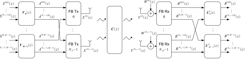
Fig. 1. MIMO FB transceiver with sub-channel precoder and equaliser based on the a polynomial SVD of the channel matrix.
II. POLYNOMIALSVD-BASEDPRECODING AND EQUALISATION
We consider a general linear time invariant (LTI) MIMO channel with NT transmit andNR receive antennas which is
characterised by an NR×NT matrix of impulse response
c[n] = ⎡ ⎢ ⎣
c1,1[n] · · · c1,NT[n]
..
. . .. ...
cNR,1[n] · · · cNR,NT[n]
⎤ ⎥
⎦, (1)
where ci,k[n] represents the finite channel impulse response between the kth transmit and the ith receive antennas. This channel matrix in (1) can also be written as
c[n] = Lc−1
=0
cδ[n−], (2)
whereδ[n]is the Kronecker function,Lc is the channel order,
and the matrixc∈CNR×NT contains theth time slice of the
FIR MIMO channel, i.e. c =c[]. The z-transform of c[n],
denoted by C(z) =Z{c[n]} ∈CNR×NT(z), is a polynomial matrix of size NR×NT and order Lc−1. Mathematically,
C(z)can be written as
C(z) = Lc−1
n=0
cnz−n . (3)
In analogy to optimal processing of narrowband MIMO systems by means of an SVD [9], [2] and [4] a precoding and equalization design for a single carrier transceiver is proposed, which exploits the polynomial SVD (PSVD) in order to decouple a broadband MIMO system matrix into
min{NT, NR}independent SISO subchannels. The PSVD of the polynomial channel matrix yields
C(z) =U(z)Σ(z)V†(z), (4)
where Vi†(z) = VHi (1/z∗) denotes the parahermitian
operation, and U(z) ∈ CNR×NR(z) and V(z) ∈
CNT×NT(z) are paraunitary matrices. Paraunitary matrices fulfillU(z)U†(z) =INR, whereINR is theNR×NRidentify matrix.
We assume that the MIMO system possesses a number of transmit antennas greater or equal to the number of receive antennas, NR ≥ NT, and that the channel C(z) has no
common zeros across all its transfer functions Z{ci,k[n]}, i = 0· · ·(NT −1). In such a case, the polynomial matrix
Σ(z)∈CNR×NT(z)can be written as
Σ(z) = Σ˜(z)
0(NR−NT)×NT
, (5)
where we define the diagonal matrix Σ˜(z) = diag{Σ0(z),· · · ,ΣNT−1(z)}, and 0A×B ∈ CA×B as a matrix with zero entries.
Using the matrixV(z)as a filter bank precoder andU†(z)
as an equalizer matrix, the equivalent overall MIMO channel is decoupled into NR independent subchannels, canceling
co-channel interference. It is worth noting that this type of precoding and equalization is not designed to remove ISI, and dispersive subchannels with transfer functions Σi(z)
remain [4]. As a drawback, the computational complexity of the PSVD approach is of orderO(L3C)and can be prohibitive.
The remaining ISI caused by the frequency selective chan-nels Σi(z), can be addressed employing a modulated FB system on each antenna. If the number of sub-channels, M, approaches infinity, the equivalent sub-channel MIMO impulse responses are no longer time dispersive. However, in feasible implementationsM might not be large enough and the equivalent sub-channel response could be still time dispersive. We propose an architecture based on the use of a PSVD decomposition on each FB sub-channel to address both the inter antenna interference and the inter-symbol interference. This approach has a lower computational complexity w.r.t the single carrier case, since the equivalent MIMO sub-channel impulse response is much shorter than the broadband MIMO channel.
In the following section we present the system model.
III. PRECODEDMIMO FB MODULATIONSYSTEM In this section we describe the proposed MIMO system model considering NT antennas at the transmitter and NR
antennas at the receiver. The general scheme is depicted in Fig. 1.
A. MIMO FB Modulation Transmitter
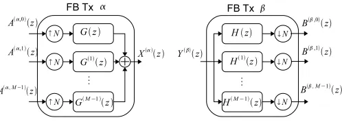
Fig. 2. Synthesis FB providing the signal for theαth transmit antenna, and analysis FB operating on theβth receive antenna.
depicted in Fig. 2 filteringM data streams at symbol rate
x(α)[n] = M−1
k=0
∈Z
a(α,k)()g(k)[n−N ] . (6)
Applying the z-transform to (6) we obtain
X(α)(z) = M−1
k=0
A(α,k)(zN)G(k)(z), , (7)
whereM is the number of the transmitter sub-channels, andN is the interpolation factor to obtain transmit signals operated atN times the symbol rate. According to (7), the M symbol rate data streams A(k)(z) are upsampled by a factor N and then filtered by pulses G(k)(z) = G(z e−j2Mπk) which are modulated versions of a prototype pulse with transfer function G(z). Thereafter, the sub-channel streams are summed and transmitted.
B. MIMO Precoding
The NT streams at the kth input of each FMT system are
obtained as
A(k)(z) =Vk(z)S(k)(z), (8)
where A(k)(z) ∈ CNT×1(z) denotes the NT-element vector of transmit signals A(α,k)(z) associated with the kth FMT sub-channel. The vector S(α,k)(z) ∈ CNT×1(z) contains NT signals S(α,k)(z) = Z{s(α,k)[n]} where s(α,k)[n] are spatially and temporally uncorrelated symbols belonging to a constellation set such as QAM with zero mean and variance σs2. The polynomial precoder matrix Vk(z) ∈ CNT×NT(z)
defined in (4) as the polyphase synthesis matrix of a filter bank of order Lv
Vk(z) = Lv−1
n=0
vk,nz−n , (9)
which comprises of FIR filters whose nth time slide is given by vk,n∈CNT×NT.
The NT transmitted signals X(α)(z) are sent over the MIMO channelC(z)∈CNR×NT(z), whose transfer function is defined in (3).
C. MIMO FB Modulation Receiver
The received signal at theβth antenna denoted byY(β)(n)
is affected by additive white Gaussian noise W(β)(z), and processed by an analysis FB (FB Rx) whose outputs are
B(β,i)(z) =PN
(Y(β)(z) +W(β)(z))H(i)(z)
, (10)
where we define the periodic repetition operation
PN[P(z)] = 1
N
N−1
k=0
P(z1/Nej2Nπk) . (11)
According to (10), the signal Y(β)(z) is filtered by the modulated filtersH(i)(z) =H(z e−j2Mπi), where H(z)is the prototype pulse of the analysis bank.
D. MIMO Equalisation
Theith outputs of the FMT receivers are processed by the equalization matrixU†i(z)∈CNR×NR(z)as
R(i)(z) =U†
i(z)B(i)(z), (12)
where B(i)(z) ∈ CNR×1(z) denotes a vector containing the NR signals B(β,i)(z) associated with the ith FMT
sub-channels and theβth receiver antenna. The vectorR(β,k)(z)∈
CNR×1(z) contains the NR output signals R(β,i)(z). The
equalizer matrixUi(z)∈CNT×NT is defined in (4) as a filter bank with polyphase analysis matrix of orderLu
Ui(z) = Lu−1
n=0
ui,nz−n, (13)
whosenth time slice is given by uk,n∈CNT×NT.
IV. FILTERBANKTRANSCEIVERS WITHTIME OR FREQUENCYCONFINEMENT
In this paper we consider and compare two classes of modulated FB transceivers. Firstly, we employ a filter bank based on a prototype with finite support in the time domain — here termed as time-confined. Secondly, an FB with filters confined to a finite interval in the frequency domain is utilised. Orthogonal frequency division multiplexing (OFDM) be-longs to a class of FB systems with time confined pulses. It employs a rectangularly shaped time domain prototype filters
g[n] =√1
Nrect
n
N
, (14)
whererect[n/N] = 1ifn∈ {0,· · · , N−1},0otherwise. The number of sub-channels of the FB is denoted as M, and the interpolation factor isN=M+TCPwhereTCPis the length of the cyclic prefix (CP), measured in sampling periods. The prototype pulse for the analysis FB in the receiver is given by h[n] = √1
Mrect n
M
FB systems with frequency confined pulses are also referred to as filtered multitone (FMT) systems. Due to this con-finement, inter-channel interference (ICI) becomes negligible. FMT system generally use matched filters that guarantee that SNR at the receiver is maximised. Ideal FMT uses sinc-shaped prototype pulses
g[n] =h[−n] = √1
Nsinc
n
N
. (15)
In presence of a frequency selective channel, FMT suffers from inter-symbol interference (ISI), which can be mitigated by sub-channel equalization. In order to limit ISI, common choice of prototype pulse is the root-raised cosine filter instead of the sinc pulse.
V. CAPACITY
In this section we define the signal to interference plus noise ratio (SINR) and the capacity, that are used to evaluate the performance of the proposed system.
We consider the received signal at theβth antenna and the ith sub-channel R(β,i)(z) which can be written in the time domain as
r(β,i)[n] =gEQ(β,i)[0]s(β,i)[n]
USE(β,i)[n]
+
=n
gEQ(β,i)[n−]s(β,i)[]
ISI(β,i)[n]
+w(β,i)[n] , (16)
where gEQ(β,i)[n] is the equivalent impulse response between the output r(β,i)[n]and the inputs(α,k)[n],USE(β,i)[n]is the useful signal, ISI(β,i)[n] the inter-symbol interference (ISI), and w(β,i)[n] the noise component. In (16), we assume that inter-carrier interference (ICI) is negligible, which is true for FMT in good approximation due to the very short spectral support of the pulses. For OFDM, it is assumed that the CP is sufficiently long to neglect ICI.
Assuming stationarity, the SINR experienced at theith sub-channel and at theβth antenna can be written as
SINR(β,i)=
1 SNR(β,i) +
1 SIR(β,i)
−1
, (17)
where in (17) we define the signal to noise ratio (SNR) and the signal to interference ratio (SIR) respectively as SNR(β,i)=
PUSE(β,i)/Pw(β,i) andSIR(β,i)=PUS(β,i)/PISI(β,i), where we denote
the average powers of the useful signal, the interference, and the noise respectively as PUSE(β,i) = E{|USE(β,i)[0]|2}, PISI(β,i) = E{|ISI(β,i)[0]|2}, and PN(β,i) = E{|w(β,i)[0]|2}, where E{·}is the expectation operator.
The average power of the useful signal and the ISI compo-nent can be expressed in the frequency domain as
PUSE(β,i)=Ps .5
−.5G (β,i)
EQ (ej2πf)df
2 (18)
and
PISI(β,i)=Ps .5
−.5
G(EQβ,i)(ej2πf)2df
−
.5
−.5G (β,i)
EQ (ej2πf)df 2
, (19)
whereG(EQβ,i)(z) =Z{gEQ(β,i)(n)}, the power of the transmitted data symbols is denoted as Ps, and f represents normalized
frequency relative to a sampling rate fs= 1.
The system performance that we present in the following sections is based on the information capacity of the system. For this purpose, we assume parallel Gaussian channels and statis-tically independent Gaussian distributed input signals, which render interferences also Gaussian (cf. e.g. [10]). Furthermore, by applying single tap zero forcing equalization, the capacity in [bit/s] for a given channel is
C(β) = B
N
NR−1
β=0 M−1
i=0 log2
1 + SINR(β,i)(β)
, (20)
where B is the transmission bandwidth in Hz.
VI. NUMERICALRESULTS INWLAN CHANNEL
In this section we present numerical results for the capacity of the proposed system when using either FMT or OFDM over typical WLAN channels.
A. Channel Model and Transmission Parameters
For our simulations, we adopt the IEEE 802.11 TGn channel model described in [11]. This model consists of five classes of channels representing different environments, i.e. small office, large open space/office. Both small scale multipath fading and large scale path loss fading as a function of distance are incorporated in this model. In particular, we consider the channel model of class C that has an RMS delay spread of 30 ns and of class E with an RMS delay spread of 100 ns. The transmitting and receiving antenna arrays are considered linear uniformly spaced with a specifiable distance between antenna elements. For a detailed description of the model, please refer to [11].
We assume the following system parameters. The transceiver has NT = 2 transmitting and NR = 2 receiving
antennas. The transmit antennas are spaced by one wavelength of the highest frequency component, while the receive an-tennas are spaced at half that distance. [12]. The FB system usesM = 64 sub-channels with a transmission bandwidth of
20 MHz. In the following we set the level of the transmitted signal PSD mask to −53 dBm/Hz, which represents the total power transmitted by theNT antennas. The receiver side experiences additive white Gaussian noise with a PSD equal to−168 dBm/Hz.
0 50 100 150 200 250 300 350 400 0.7
0.75 0.8 0.85 0.9 0.95 1
P(C>x)
x [Mbit/s] MIMO−FMT
MIMO−OFDM
60m 10m
[image:5.612.61.288.59.181.2]CLASS C
Fig. 3. Complementary cumulative distribution function (CCDF) of the capacity considering a2×2antennas system using FMT and MIMO-OFDM over an IEEE80.11TGn class C channel model.
0 50 100 150 200 250 300 350 400 0.7
0.75 0.8 0.85 0.9 0.95 1
P(C>x)
x [Mbit/s] MIMO−FMT
MIMO−OFDM
60m 10m
CLASS E
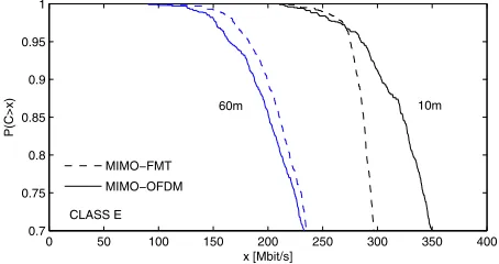
Fig. 4. Complementary cumulative distribution function (CCDF) of the capacity considering a2×2antennas system using FMT and MIMO-OFDM over an IEEE802.11TGn class E channel model.
B. Simulation Results
For the class C and E models detailed in Sec. VI-A, large ensembles of random channel realizations for distances of 10m and 60m between Tx and Rx arrays have been simulated. For these ensembles, Fig. 3 and Fig. 4 show the complemen-tary cumulative distribution functions (CCDF) for the system capacity. It is interesting to note that with probability 0.9, MIMO-FMT provides a capacity increase of 15% and 6% for class C over MIMO-OFDM for distances of 10m and 60m, respectively. While for class E, MIMO-FMT achieves a 7% advantage over MIMO-OFDM for the 60m distance. At the shorter distance of 10m, the advantage is reversed, and MIMO-OFDM achieves a 13% advantage over MIMO-FMT.
MIMO-OFDM provides an advantage in the case of channel class E for the shorter 10m distance, where the low path-loss provides relatively high SNR and the ISI dominates the performance of MIMO-FMT. While dispersive, the channel is however sufficiently short for OFDM to suppress all inter-block and inter-carrier interferences with its sufficiently long CP. In the cases where the SNR is not too high, MIMO-FMT gains from employing matched filtering for a superior performance in noise.
Although not reported, improved performance in FMT can be achieved with linear sub-channel equalization to better suppress the residual sub-channel ISI.
VII. CONCLUSIONS
In this paper we have presented a MIMO transceiver based on FB modulation systems and on the PSVD decomposition. In particular, we have considered two types of FB which deploys either time confined prototype pulses (OFDM) or frequency confined prototype pulses (FMT). We have shown the performance in terms of capacity of the considered systems in typical WLAN channels. MIMO-FMT can afford higher ca-pacity compared to MIMO-OFDM only in certain conditions, in particular when the power level of the noise at the receiver is higher than the power level of the interferences. In presence of high interference power, MIMO-OFDM is the best option because due to the CP it can cope with limit imposed by the interference.
REFERENCES
[1] D. P. Palomar, J. M. Cioffi, and M. A. Lagunas, “Joint Tx-Rx Beam-forming Design for Multicarrier MIMO Channels: A Unified Framework for Convex Optimization.,”IEEE Trans SP, vol. 51, no. 9, p. 23812401, 2003.
[2] S. Redif and T. Cooper, “Paraunitary Filter Bank Design via a Polyno-mial Singular Value Decomposition,” inProc. IEEE International Con-ference on Acoustics, Speech, and Signal Processing, vol. 4, (Philadel-phia, PA), pp. 613–616, March 2005.
[3] J. G. McWhirter, P. D. Baxter, T. Cooper, S. Redif, and J. Foster, “An EVD Algorithm for Para-Hermitian Polynomial Matrices,” IEEE Transactions on Signal Processing, vol. 55, pp. 2158–2169, May 2007. [4] C. H. Ta and S. Weiss, “Design of Precoding and Equalisation for MIMO Broadband Transmission,” inIEE/EURASIP Conference on DSP Enabled Radio(S. Weiss, ed.), vol. 2005/11086, (Southampton, UK), pp. 30/1–30/5, September 2005.
[5] J. Bingham, “Multicarrier Modulation for data Transmission, an Idea whose Time Has Come,” IEEE Commun. Mag., vol. 31, pp. 5 – 14, May 1990.
[6] G. Cherubini, E. Eleftheriou, and S. Olcer, “Filtered Multitone Modula-tion for Very High-Speed Digital Subscribe Lines,”IEEE J. Sel. Areas Commun., pp. 1016–1028, June 2002.
[7] A. M. Tonello, “Performance Limits for Filtered Multitone Modulation in Fading Channels,”IEEE Trans. Wireless Commun., vol. 4, pp. 2121– 2135, September 2005.
[8] M. Harteneck, S. Weiss, and R. Stewart, “Design of Near Perfect Reconstruction Oversampled Filter Banks for Subband Adaptive Filters,” IEEE Transactions on Circuits and Systems II: Analog and Digital Signal Processing, vol. 46, no. 8, pp. 1081–1085, 1999.
[9] M. Vu and A. Paulraj, “MIMO Wireless Linear Precoding,”IEEE Signal Processing Magazine, vol. 24, pp. 86–105, Sept. 2007.
[10] J. Seoane, S. Wilson, and S. Gelfand, “Analysis of Intertone and Interblock Interference in OFDM when the Length of the Cyclic Prefix is Shorter than the Length of the Impulse Response of the Channel,” in Proc. of IEEE Global Telecommunications Conference (GLOBECOM), (Phoenix, AZ, USA), pp. 32–36, Nov. 1997.
[11] V. Ercegl, L. Shumacher, and et al, “IEEE P802.11 Wireless LANs, TGn Channel Models, doc.: IEEE 802.11-03/940r4,” 2004.
[image:5.612.60.287.244.364.2]