Ultrashort-pulse laser with an intracavity phase
shaping element
N.K. Metzger,1,* W. Lubeigt,2 D. Burns,2 M. Griffith,3 L. Laycock,3 A.A. Lagatsky,1 C.T.A. Brown,1 and W. Sibbett1
1SUPA School of Physics and Astronomy, University of St Andrews, North Haugh, St Andrews, Fife, KY16 9SS, UK 2Institute of Photonics, University of Strathclyde, Wolfson Centre, 106 Rottenrow, Glasgow G4 0NW, UK 3BAE Systems Advanced Technology Centre, West Hanningfield Road, Great Baddow, Chelmsford, CM2 8HN, UK
*nkm2@st-andrews.ac.uk
Abstract: A novel ultrashort-pulse laser cavity configuration that incorporates an intracavity deformable mirror as a phase control element is reported. A user-defined spectral phase relation of 0.7 radians relative shift could be produced at around 1035 nm. Phase shaping as well as pulse duration optimization was achieved via a computer-controlled feedback loop.
©2010 Optical Society of America
OCIS codes: (140.3410) Laser resonators; (140.4050) Mode-locked lasers; (140.7090) Ultrafast lasers; (320.1590) Chirping; (320.5540) Pulse shaping; (320.5520) Pulse compression; (140.0140) Lasers and laser optics; (320.0320) Ultrafast optics; (010.1080) Active or adaptive optics; 050.5080 Phase shift.
References and links
1. P. O. E. Martinez, J. P. Gordon, and R. L. Fork, “Negative group-velocity dispersion using refraction,” J. Opt. Soc. Am. B 1(10), 1003–1006 (1984).
2. R. L. Fork, O. E. Martinez, and J. P. Gordon, “Negative dispersion using pairs of prisms,” Opt. Lett. 9(5), 150– 152 (1984).
3. E. Zeek, K. Maginnis, S. Backus, U. Russek, M. Murnane, G. Mourou, H. Kapteyn, and G. Vdovin, “Pulse compression by use of deformable mirrors,” Opt. Lett. 24(7), 493–495 (1999).
4. P. Baum, S. Lochbrunner, L. Gallmann, G. Steinmeyer, U. Keller, and E. Riedle, “Real-time characterization and optimal phase control of tunable visible pulses with flexible compressor,” Appl. Phys. B 74(9), s219– s 224 (2002).
5. J. Garduno-Mejıa, A. H. Greenaway, and D. T. Reid, “Programmable spectral phase control of femtosecond pulses by use of adaptive optics and real-time pulse measurement,” J. Opt. Soc. Am. B 21, 833–843 (2004). 6. A. Baltuška, and T. Kobayashi, “Adaptive shaping of two-cycle visible pulses using a flexible mirror,” Appl.
Phys. B 75(4-5), 427–443 (2002).
7. T. Binhammer, E. Rittweger, U. Morgner, R. Ell, and F. X. Kärtner, “Spectral phase control and temporal superresolution toward the single-cycle pulse,” Opt. Lett. 31(10), 1552–1554 (2006).
8. F. Verluise, V. Laude, Z. Cheng, C. Spielmann, and P. Tournois, “Amplitude and phase control of ultrashort pulse by use of an acousto-optic programmable device,” Opt. Lett. 25, 575–577 (2000).
9. P. Wnuk, C. Radzewicz, and J. S. Krasiński, “Bimorph piezo deformable mirror for femtosecond pulse shaping,” Opt. Express 13(11), 4154–4159 (2005).
10. R. Bartels, S. Backus, E. Zeek, L. Misoguti, G. Vdovin, I. P. Christov, M. M. Murnane, and H. C. Kapteyn, “Shaped-pulse optimization of coherent emission of high-harmonic soft X-rays,” Nature 406(6792), 164–166 (2000).
11. A. Sharan, and D. Goswami, “Prospect of ultrafast pulse shaping,” Curr. Sci. 82, 30–37 (2002).
12. W. S. Warren, H. Rabitz, and M. Dahleh, “Coherent Control of Quantum Dynamics: The Dream Is Alive,” Science 259(5101), 1581–1589 (1993).
13. D. Meshulach, and Y. Silberberg, “Coherent quantum control of two-photon transitions by a femtosecond laser pulse,” Nature 396(6708), 239–242 (1998).
14. H. Rabitz, M. Motzkus, K. Kompa, K. Kompa; de Vivie-Riedle R, “Whither the future of controlling quantum phenomena?” Science 288(5467), 824–828 (2000).
15. J. C. Dainty, A. V. Koryabin, and A. V. Kudryashov, “Low-order adaptive deformable mirror,” Appl. Opt. 37(21), 4663–4668 (1998).
16. T. Y. Cherezova, L. N. Kaptsov, and A. V. Kudryashov, “Cw industrial rod YAG:Nd3+ laser with an intracavity active bimorph mirror,” Appl. Opt. 35(15), 2554–2561 (1996).
17. W. Lubeigt, M. Griffith, L. Laycock, and D. Burns, “Reduction of the time-to-full-brightness in solid-state lasers using intra-cavity adaptive optics,” Opt. Express 17(14), 12057–12069 (2009).
19. W. Lubeigt, G. Valentine, and D. Burns, “Enhancement of laser performance using an intracavity deformable membrane mirror,” Opt. Express 16(15), 10943–10955 (2008).
20. P. Welp, H. -. Heuck, and U. Wittrock, “Intracavity adaptive optics optimization of an end-pumped Nd:YVO4 laser,” in CLEO/Europe and IQEC 2007 Conference Digest, (Optical Society of America, 2007), paper CC_12. 21. P. Yang, Y. Liu, W. Yang, M.-W. Ao, S.-J. Hu, B. Xu, and W.-H. Jiang, “Adaptive mode optimization of a
continuous-wave solid-state laser using an intracavity piezoelectric deformable mirror,” Opt. Commun. 278(2), 377–381 (2007).
22. A. A. Lagatsky, E. U. Rafailov, A. R. Sarmani, C. T. A. Brown, W. Sibbett, L. Ming, and P. G. R. Smith, “Efficient femtosecond green-light source with a diode-pumped mode-locked Yb3+:KY(WO
4)2 laser,” Opt. Lett. 30(10), 1144–1146 (2005).
23. BAE systems Advanced Technology Centre, West Hanningfield rd, Great Baddow, Chelmsford CM2 8HN, UK. 24. R. Paschotta, and U. Keller, “Passive mode locking with slow saturable absorbers,” Appl. Phys. (Berl.) 73, 653–
662 (2001).
25. P. O’Shea, M. Kimmel, X. Gu, and R. Trebino, “Highly simplified device for ultrashort-pulse measurement,” Opt. Lett. 26(12), 932–934 (2001).
26. S. Akturk, M. Kimmel, P. O’Shea, and R. Trebino, “Extremely simple device for measuring 20-fs pulses,” Opt. Lett. 29(9), 1025–1027 (2004).
27. P. O’Shea, S. Akturk, M. Kimmel, and R. Trebino, “Practical issues in ultra-short-pulse measurements with ‘GRENOUILLE’,” Appl. Phys. B 79(6), 683–691 (2004).
28. L. L. C. Swamp Optics, http://www.swampoptics.com/.
29. Private communication, Dr. Dongjoo Lee, Research Scientist Swamp Optics LLC. 30. L. L. C. Mesa Photonics, http://www.mesaphotonics.com/.
31. C. R. Houck, J. A. Joines, and M. G. Kay, “A Genetic Algorithm for Function Optimization: A Matlab Implementation,” http://www.ise.ncsu.edu/mirage/GAToolBox/gaot/
32. L. Davis, Genetic Algorithms and Simulated Annealing, (Pitman Publishing 1987)
33. S. Akturk, M. Kimmel, P. O’Shea, and R. Trebino, “Measuring pulse-front tilt in ultrashort pulses using GRENOUILLE,” Opt. Express 11(5), 491–501 (2003).
34. A. A. Lagatsky, N. V. Kuleshov, and V. P. Mikhailov, “Diode-pumped CW lasing of Yb:KYW and Yb:KGW,” Opt. Commun. 165(1-3), 71–75 (1999).
35. C. Radzewicz, P. Wasylczyk, W. Wasilewski, and J. S. Krasiński, “Piezo-driven deformable mirror for femtosecond pulse shaping,” Opt. Lett. 29(2), 177–179 (2004).
36. K. F. Kwong, D. Yankelevich, K. C. Chu, J. P. Heritage, and A. Dienes, “400-Hz mechanical scanning optical delay line,” Opt. Lett. 18(7), 558–560 (1993).
37. D. Brida, G. Cirmi, C. Manzoni, S. Bonora, P. Villoresi, S. De Silvestri, and G. Cerullo, “Sub-two-cycle light pulses at 1.6 microm from an optical parametric amplifier,” Opt. Lett. 33(7), 741–743 (2008).
38. J. Garduño-Mejía, A. H. Greenaway, and D. T. Reid, “Designer femtosecond pulses using adaptive optics,” Opt. Express 11(17), 2030–2040 (2003).
1. Introduction
Commercial ultrafast lasers are now well engineered to provide users with ultrashort pulses at high peak powers. In general, beam delivery and shaping optics are commonly placed in the beam path and so group delay dispersion (GDD) is omnipresent resulting in pulses that may be frequency chirped and / or stretched in time. Such dispersive effects can be compensated by introducing a grating or prism pulse compressor [1,2] into the beam path but these passive pulse compressors tend to suffer from limited flexibility in terms of individual phase control or pulse shaping, owing to the interdependence of the different phase orders. To generate ultrashort pulses having user-defined phase characteristics usually involves the use of an adaptive optics pulse shaper [3–8] where deformable mirrors are often preferred over liquid crystal or acousto-optic pulse shapers when losses are of key importance [9].
Over the past decade or so, pulse shaping techniques for ultrafast lasers have seen a substantial growth because of widening and far-ranging applications. Examples include the study of some of the fundamental laser physics, the control of intra-molecular vibration rotation, problems in chemistry, and optical manipulation at the cellular level in biology [10,11]. The manipulation of the pulse profile by controlling the spectral phase shape only has also been used as an enabling tool in a range of implementations either to influence the outcome of chemical reactions or to provide quantum-mechanical control [12–14]. In previously reported work, these shaping methods have been performed external to the laser cavity. By contrast, to date it has only been in the regime of spatial laser mode control that deformable mirrors have been shown to be a versatile intracavity element [15–21].
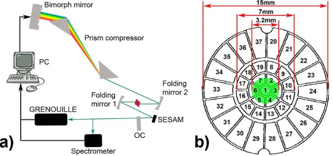
described. The primary goal in this work was to assess experimentally the capabilities of this novel design for an ultrashort-pulse laser that incorporates a bimorph deformable mirror as an adaptable in situ phase-control element. Conceptually, the implementation and function of the intracavity mirror design is similar to its extracavity counterpart in that a prism pair combined with a spherical mirror can be used to map out spatially the spectral components of the pulse onto the surface of a bimorph mirror (see Fig. 1). An imposed deformation of the bimorph mirror delays or advances the phase of the individual components by a change in propagation length that is twice the deformation or stroke of the mirror surface. Consequently, optical pulses having user-defined phase relations can be obtained directly from the laser oscillator.
2. Laser and experimental setup
An asymmetric, z-folded cavity was designed having three intracavity foci located at the bimorph mirror, the output coupler (OC) and the gain material. A 1.2-mm-long 10 at.% Yb:KYW crystal was used as a gain medium placed between two concave focusing mirrors M1, M2 having 50 mm, 75 mm radii of curvature respectively [22], in the layout as illustrated in Fig. 1 a).
Fig. 1. a) Laser cavity design and feedback loop. b) Bimorph mirror front surface. The mirror with 37 actuator elements has an active aperture of 7 mm, of which 3.2 mm were occupied by the cavity mode (marked in green).
The pump sources were two single-mode fibre-coupled, polarization-maintaining InGaAs diode lasers emitting at 980.5 nm that produced a combined pump power of 900 mW. The length of the short arm was set to 170 mm and accommodated a 1% output coupler and a quantum well (QW) semiconductor saturable absorber mirror (SESAM) that had a 1.2% modulation depth at 1045 nm and a relaxation time of about 5 ps. The SESAM was placed at an angle of 12° at a distance of 15 mm from the output coupler, the beam waist radius (at the 1/e2 level) was evaluated via ABCD matrix calculation to be 99.8 µm at the position of the SESAM and 73.6 µm at the position of the OC for a plane bimorph mirror surface.
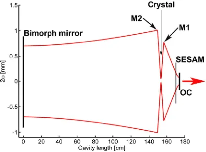
[image:3.612.140.475.257.415.2]Rayleigh range of the long cavity arm (of about 1.5 m) and therefore we presume to be ceaselessly operating in the Fourier plane.
Fig. 2. Simulated mode of the laser cavity with the position of the individual components as indicated. This shows that the bimorph mirror is placed at one of the Fourier planes of the cavity and that the SESAM location is not at a focal point of the cavity.
With this cavity configuration the laser produced pulses centred at 1035 nm with an output power of 60 mW at a repetition frequency of 95 MHz. The bimorph mirror [17,23] used had a multilayer dielectric coating for a central wavelength of 1064 nm and was actuated by 37 piezo-electric transducer (PZT) elements. It had an active aperture of 7 mm containing 19 electrodes while 18 boundary electrodes extend the accessible aperture to 15 mm. The cavity mode covered the 7 central actuators where the spot size on the mirror is defined by the spectrum of the laser pulses and for a spectral width of 6 nm the transverse beam diameter (1/e2) was measured to be 3.2 mm (shown in Fig. 1 b). An approximate spectral resolution of 3 nm per actuator is obtained. In practice however the surface response and hence the resolution is dependent on all the actuators. Even with only a few actuators covered, this setup should allow for the realization of different order phase shapes. As the mirror surface response to changes in actuator settings is modal it was chosen to operate all 37 actuators of the deformable mirror for the experiments presented here. It is however expected that the outer rim actuators of the mirror have far less influence in the total deformation of the mirror than the central actuators. No thermal deformation of the intracavity bimorph mirror surface [18] was observed and stable mode locking with a flat phase profile was maintained over extended periods of laser operation. Manipulation of the mirror surface was controlled by addressing the individual 37 PZT elements via a personal computer.
During the phase optimization process a spectrometer was used to monitor the output spectrum from the laser. From the results obtained it was clearly evident that stable mode-locked operation of the laser could be established and readily maintained. Additionally, the output from the spectrometer was used as an additional decision channel in the optimization process so that unwanted features such as cw-spikes, multiple-pulsing or mode competition could be avoided. As part of the phase optimization procedures optical and radio frequency (RF) spectra were used to confirm SESAM-based mode locking [24].
[image:4.612.207.415.107.260.2]3. Phase optimization algorithm
A feedback loop was implemented with a genetic optimization algorithm (GOA) [19,31,32] to achieve a user-defined phase shape. The advantage of such an algorithm in combination with a feedback loop is that the influence matrix of the deformable mirror [5] does not need to be known. The GOA converged rapidly towards the targeted phase shape and showed no sensitivity to phase fluctuations (which were at the order of 3.5% of the measured phase value) and the hysteresis (< 3% in the operation range) associated with the piezoelectric transducers of the bimorph mirror [23]. Prior to each shaping process the mirror was cleared of any residual hysteresis and set to its plane profile. During optimization the algorithm operated within previously established boundary conditions for the mirror deformation, to maintain the condition for stable mode locking of the laser. Given that the shape of the spectrum is dependent on the laser operating regime, the spectrometer data were used by the algorithm as a quality parameter to assess the laser stability, such that, for example, Q-switching instabilities could be eradicated during the shaping process. The phase shaping with the GOA is an iterative process and depending on the desired phase shape the algorithm converged within 20 minutes and could be terminated by the user whenever no further improvement towards the target spectral phase was evident. Interestingly, in one of the alternative assessment procedures evaluated in this study, the pulse duration rather than a user-defined spectral phase was used as an optimization target.
4. Measurement methods
Several methods were then used in subsequent measurements to ensure their robustness. For example, input beam misalignment exceeding ± 6 mrad can lead to erroneous phase retrieval of the GRENOUILLE [27]. To ensure the validity of our GRENOUILLE measurements the beam walk-off from the laser during phase shaping was evaluated, by measuring the output mode displacement of the beam with the beam profiling option of the GRENOUILLE. A beam pointing stability of better than 1 mrad for intracavity deformable mirror radii between 4.8 m to −4.6 m was achieved and it can be concluded that there was no significant beam walk-off during the GOA optimization. This is in agreement with observations of the retrieved central wavelength before and after GOA optimization where an input beam misalignment over ± 3 mrad is evident as shifts in the retrieved center wavelength which were not observed in the measurements. The raw GRENOUILLE trace can also be used as an indicator for beam displacement. In this case, a distorted trace indicates a displaced input beam of greater than ± 6 mrad [27].
Spatio-temporal distortions in pulses constitute another issue that must be addressed in a phase-shaped laser using a two-dimensional deformable mirror. Although the deformable mirror is placed at the Fourier plane of the asymmetric cavity it is important to assess whether the pulse shaping mechanism imposes pulse front tilt or spectral chirp on the shaped pulse, because this would imply some time-space coupling in the designed cavity. Both spatio-temporal distortions can be considered using the measured GRENOUILLE trace (measured SHG signal) [33] and are observable as either displacement of the SHG trace for pulse front tilt or shear of the trace for spatial chirp where the magnitude of displacement and shear are related linearly to the amount of spatial-temporal distortions of the pulse. Again, the measured GRENOUILLE trace was used in subsequent phase shaping results before and after phase shaping with the GOA to demonstrate that such spatial-temporal distortions were absent from the test laser. A robust indication of accurate pulse retrieval is the FROG trace error which should not change significantly during the shaping process, as it indicates an askew input beam [27]. Typically, a FROG trace error of 0.017 was achieved, which changed by only 0.001 when the phase was optimized.
During phase shaping, the mirror deformation can be rather complex because the 37 actuators are set to different voltages. To model such a complex intracavity mirror surface would be beyond the scope of this paper and so, for this reason, the response was approximated with an average voltage applied over all 37 actuators. With this approximation concave and convex mirror surfaces having radii of 35.4 m and −56.6 m were deduced as the two representative phase shaping examples shown in Fig. 6, 7. In Table 1 the cavity waist radii are given for the crystal and the SESAM with the different radii of curvature, r = 35.4 m, r = −56.6 m and these are compared to a plane mirror surface. As indicated, the changes to the waist radius at the crystal and SESAM during phase shaping were less than 1µm and can therefore be deemed too small to affect the nonlinearities in the crystal or the SESAM.
Table 1. Mirror radius of curvature (r) and the associated waist radii (ω at the 1/e2 level) at the crystal and the SESAM.
Mirror curvature r [m] ωcrystal [µm] ωSESAM [µm]
35.4 12.8 100.8
Plane 12.6 99.8
−56.6 12.4 99.7
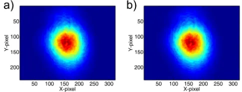
Additionally the change in the output beam profile of the laser for a plane and concave deformable mirror setting were experimentally recorded with a CCD camera (Fig. 3), with no significant spatial beam changes being evident.
Fig. 3. a) Laser mode for a plane deformable mirror surface. b) Laser mode for a concave (r = 35 m) mirror surface.
The changes in intracavity losses within the cavity in these phase shaping assessments were also scrutinized to eradicate any influence of the laser operating regime to the phase of the pulse. Beam power fluctuations were quantified before and after phase shaping and these were less than 5%. Also, the spectrum was monitored continuously to quantify any wavelength shifts (∆λcentral) that would imply changes in intracavity losses [34] and thus
indicate different laser operating regimes but in these assessments they were less than 1 nm. This also ensures accurate pulse retrieval from the GRENOUILLE because it is a relative spectral measurement, where the central operating wavelength is calibrated by the user.
5. Experimental results
The experimental results presented here show how this laser system can perform self-optimization by minimizing the pulse duration and how the spectral phase is influenced accordingly. Secondly, the different types of phase shapes that can be realized are demonstrated.
5.1 Self optimization
As an initial route to evaluate the versatility of the setup, a pulse duration optimization run was performed. In this process the fitness factor was calculated from the difference between the measured pulse duration and a minimal target pulse duration (Fitness = τpulse- τtarget), such
[image:6.612.181.423.301.393.2]minimization. Specifically, it shows input 278-fs pulses being improved by a factor of 1.36 to have final durations of 204 fs. During this optimization the measured spectrum increased from
∆λ = 3.9 nm to ∆λ = 6.2 nm while the time-bandwidth product (∆τ∆υ) improved from 0.38 to 0.36. Importantly, a ‘flattening’ of the phase profile was also observed. The stability of the measured pulses was tested over 10 minutes and, after flattening the mirror surface, the pulses broadened again to 270 fs.
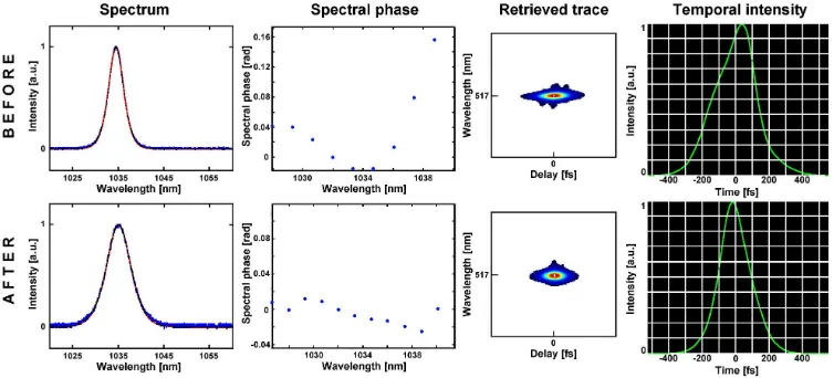
Fig. 4. Pulse duration optimization: Top row (from left to right) pulse parameters before optimization: initial spectrum, spectral phase, retrieved GRENOUILLE trace and initial temporal intensity. At the beginning of the optimization procedure the spectral width is 3.9 nm and the spectral phase fluctuates by > 0.16 rad, the pulses at this initial stage had durations of 278 fs. Bottom row, pulse parameters after optimization by the GOA (left to right): the spectral width has increased to 6.2 nm but importantly the spectral phase variations have decreased to < 0.04 rad. The retrieved GRENOUILLE and temporal intensity trace indicates that the pulse durations have shortened to 204 fs.
Furthermore, the GOA could be amended readily to monitor the pulse durations continuously and whenever the pulses broadened beyond a user-defined threshold the GOA would be restarted to optimize the cavity towards shorter pulses. Access to this modification enabled pulse duration optimization as well as the active stabilization of pulse duration.
5.2 User-defined phase shapes
In this case the GOA was applied to optimize the pulse phase to a user-defined target shape. The user thus defines via a formula (linear, quadratic or cubic) the target phase shape to which the GOA should optimize the laser output through changes in the actuator settings of the bimorph mirror. The results presented in Figs. 5-7, 9 show the spectrum, the target or user-defined spectral phase (black dots with line) together with the measured spectral phase (as blue dots) and the measured GRENOUILLE trace with a flat mirror surface (top row, labeled BEFORE) and after optimization by the feedback loop (bottom row, labeled AFTER). The measured GRENOUILLE trace is included to indicate any shift, walk off or skewing in the trace due to phase shaping, as already discussed.
[image:7.612.118.495.144.315.2]Fig. 5. Flat phase optimization: The top row shows the initial spectrum, initial spectral phase (blue dots) and target phase (black dots with line) with the measured GRENOUILLE trace. The initial spectrum has a width of ∆λ = 5.1 nm with a flat phase. After initiating the GOA (bottom row) the spectral width (bottom left) has increased to ∆λ = 6.1 nm, while the spectral phase has maintained its flat shape and started to extend (as the spectral width has increased). Importantly, the GOA was able to further optimize the laser and shorten the pulses from 251 fs to 210 fs, while maintaining a flat phase profile as defined by the user.
This offers the prospect of obtaining significantly reduced pulse durations from a simple femtosecond laser because different (higher) orders of frequency chirp can be compensated in a manner that is not feasible with intracavity prisms alone. This is important for femtosecond lasers that generate pulses with durations below 50 fs. The change in spectral width indicates that in this instance, this is not a pure phase-shaping process because the spectral width is altered while the cavity condition is being optimized. Rather, it illustrates the interdependence of the spectral, phase and duration characteristics of an evolving ultrashort pulse. By contrast, for the examples that follow, spectral changes are not observed and pure phase shaping is realized.
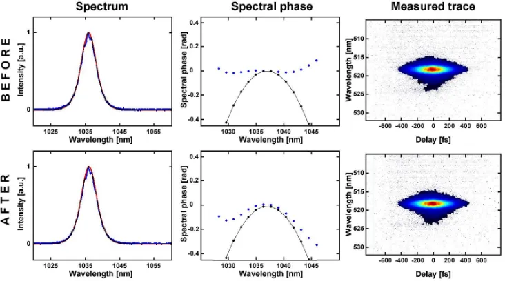
[image:8.612.117.485.74.281.2]Fig. 6. Positive quadratic phase optimization: The top row shows the initial spectrum (∆λ = 5.1 nm), initial spectral phase (blue dots) which is nearly flat and the target quadratic phase (black dots with line), as well as the measured GRENOUILLE trace. After initiating the GOA (bottom row) the spectral width remained constant at ∆λ = 5.3 nm while the spectral phase has changed its initially flat outline and started to converge towards the positive quadratic profile designed by the user and showing a maximum phase shift of over + 0.4 rad. Importantly, the measured GRENOUILLE trace remains undistorted.
Fig. 7. Negative quadratic phase optimization: The top row shows the initial spectrum (∆λ = 5.2 nm), initial spectral phase (blue dots) and the target negative quadratic phase (black dots with line), as well as the measured GRENOUILLE trace. After initiating the GOA (bottom row) the spectral width was measured to be ∆λ = 5.4 nm and the spectral phase starts to converge towards the negative quadratic profile designed by the user with a maximum phase shift of over −0.3 rad. Again the measured trace shows no indication of distortion.
[image:9.612.118.484.356.560.2]an approximated average mirror response that could be transferred into a total mirror curvature in dioptres given that the total deflection of the mirror surface is a linear combination from all the actuators [23,35]. With prior knowledge of the laser mode radius on the mirror and the stroke of the mirror, the maximum phase change in radians for a central wavelength of 1036 nm could then be calculated.
This is believed to be a valid approximation for the estimation of the mirror stroke (∆x) and thus the total phase change (∆φ), especially for a quadratic phase shape. Here a positive-sign deformation of the mirror will indicate a concave shape and a negative positive-sign for a convex shape, which correspond to phase advance (positive frequency chirp) or delay (negative frequency chirp) respectively, with the phase change being relative to the central wavelength.
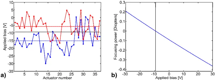
With this caveat it is possible to plot the applied bias settings as a dependence of the actuator number (shown in Fig. 8 a)) for the results shown in Fig. 6 (positive quadratic phase) and Fig. 7 (negative quadratic phase). Average voltages of −15.1 V and −5.7 V respectively were obtained, where a −9.4 V setting of all actuators would correspond to a flat mirror surface. These bias voltage settings correspond to mirror profiles with the following radii of curvature [23] (shown in Fig. 8 b): a concave mirror with r = 35.4 m, producing a positive quadratic frequency chirp and a convex mirror with r = −56.6 m producing a negative quadratic frequency chirp. Based on this observation, it is clearly evident that there is no sign of any inherent ambiguity in these SHG frequency-resolved optical gating measurements.
Fig. 8. a) Applied bias voltage of the 37 actuators. The red line corresponds to the phase shape shown in Fig. 7 and is averaged as a constant bias of −5.7 V over all actuators. The blue line corresponds to the phase shape shown in Fig. 6 and is averaged as a constant bias of −15.1 V over all actuators. The horizontal black line indicates a constant bias voltage of −9.4 V for a flat mirror surface. b) This shows the mirror response in dioptre to a constant bias voltage applied to all 37 actuators. The vertical black line donates a flat mirror surface at a bias of −9.4 V where lower bias voltages cause a concave mirror shape and higher voltages cause a convex mirror shape.
From the radius of curvature and the stroke, the associated phase change for both settings was deduced to be [36] ∆ = × ∆φ k 2 x wherek=2 /π λ, relative to the zero phase shift at the central wavelength. For the concave mirror with a stroke of 0.036 µm a calculated positive phase change of 0.43 rad was obtained in agreement with the measured phase change of 0.4 rad from Fig. 6. Analogously, for the convex mirror with a stroke of −0.023 µm the negative phase change calculated to be −0.27 rad was consistent with the measured phase change of −0.3 rad. Considering the approximate nature of this approach this represented a satisfactory agreement between deflection of the mirror and the phase change and confirmed the relationship connecting these two entities.
[image:10.612.120.490.300.437.2]period of 15-20 minutes after initiation and were maintained ahead of the GOA being restarted with a new phase design.
Fig. 9. Cubic phase design: The top row shows the initial spectrum, initial spectral phase (blue dots) and the target cubic phase (black dots with line), as well as the measured trace. Middle row: this is the intermediate step that shows the optimization algorithm while still working where at the longer wavelength the spectral phase has already been adjusted but it has not been yet achieved for the shorter wavelengths in the pulse spectrum. After the GOA is stopped (bottom row) the spectral phase converged towards the cubic profile designed by the user. The spectral width remained constant at 5.3 nm, while the pulse duration increased from 225 fs to 235 fs. Again for all three instances, there are no distortions and/or shifts in the measured traces.
6. Discussion and conclusion
range to the 1 µm wavelength regime but it is anticipated that this technology can be applied readily in other spectral bands.
Additionally, it has been shown that this laser is capable of self optimization. For example, at the “push of a button” it is possible to improve the pulse duration without realigning the cavity. Importantly, this feature could assist active cavity stabilization loop procedures when changes in the performance of the laser are monitored on a continuous basis. Similar phase shaping performance would be expected from a single-dimensional bimorph mirror, however it is anticipated that the self optimization will be less significant as only the horizontal axis could be optimized. Moreover, this cavity design could have major impact in the operational regime of few-cycle lasers because it offers the prospect of compensating the higher orders of dispersion that cannot be controlled satisfactorily by prisms or GTI mirrors alone. This approach thus has the potential to provide an enabling technology to a diverse user community for whom the intracavity phase control of femtosecond lasers offers new avenues of system versatility.
Acknowledgements