Abstract--Unique and varied power system conditions are already being experienced as a result of the deployment of novel control strategies and new generation and distribution related technologies driven by the smart grid. A particular challenge is related to ensuring the correct and reliable operation of protection schemes. Implementing smarter protection in the form of adaptive setting selection is one way of tackling some of the protection performance issues. However, introducing such new approaches especially to safety critical systems such as protection carries an element of risk. Furthermore, integrating new secondary systems into the substation is a complex and costly procedure. To this end, this paper proposes an adaptive protection architecture that facilitates the integration of such schemes into modern digital substations which are a staple of smart grids. Functional features of the architecture also offer powerful means of de-risking schemes and flexible implementation through self-contained modules that are suitable for reuse. An example adaptive distance protection scheme is presented and tested to demonstrate how the architecture can be implemented and to highlight the architecture’s novel features.
Index Terms--Adaptive relaying, smart grids, scheme architecture and real-time digital simulation
I. INTRODUCTION
HORTFALLS in power system protection performance are being experienced at both transmission and distribution networks. These are due to a number of factors including increased penetration of distributed generation, varied operational conditions and severe wide area disturbances [1-3]. Maintaining acceptable protection performance is essential for a functional smart grid as these schemes ensure the reliable and safe operation of the primary system. Adaptive protection (whether using settings groups or more advanced setting calculation techniques) has been proposed as a solution to enhancing the performance of protection schemes in response to many of these factors [4]. However, a body of work tackling adaptive protection schemes from an architectural point of view and ultimately the verification and validation (V&V) of such schemes is virtually non-existent.
This paper proposes a unique requirements-driven adaptive protection architecture. Devising such an architecture not only defines the constituents of an effective adaptive protection
This research was supported by the UK Research Councils’ Energy Programme as part of the Supergen FlexNet Consortium, grant no. EP/E04011X/1.
The authors are with the Institute for Energy and Environment, Electronic and Electrical Engineering Department, University of Strathclyde, Glasgow, G1 1XW, UK. (e-mail: iabdulhadi@eee.strath.ac.uk).
scheme, but it is instrumental in delivering straightforward substation integration and effective scheme V&V. This architecture and its constituent functions aim to contribute to the set of tools and approaches that form a “toolbox of proven technical solutions” for the smart grid [5], [6]. As communications system become more widespread and a cornerstone of delivering smart grid functions [7], emerging protection technologies (including adaptive protection) must effectively make use of these communications systems while maintaining reliable operation and interoperability between different vendor solutions.
The fact that adaptive protection essentially relies on modifying its behavior based on the prevailing power system conditions [8] raises a number of concerns related to the validity of adaptive behavior, the nature and amount of information required to infer the system state and the appropriate scheme performance at any given time. These issues compared to conventional protection philosophies, present a challenge in terms of devising suitable scheme implementations and V&V procedures. The work in [9] highlights the importance of dedicated ‘testing environments’ as an effective means of tackling this issue which requires considering the impact of varied primary system operational conditions dictated by smart grid controls.
This paper first of all discusses the different life-cycle stages of a protection scheme or platform from the point of view of utilities and manufacturers respectively. This is critical to understanding the requirements necessary to develop an adaptive protection solution that meets the utilities’ expectations while not leading to a costly and impractical overhaul of secondary substation infrastructure. In light of these requirements, the paper then develops the proposed architecture with its distinct functional layers. Detailed architecture functionality is also discussed. Challenges of integrating adaptive protection schemes into modern substations are identified and the role of the architecture in overcoming these is discussed.
Finally the V&V of adaptive protection schemes, although not the focus of this paper, is an important issue that needs to be addressed. Some of the challenges associated with this are discussed and the inherent architectural features that facilitate scheme verification and validation are explained. Furthermore, an example adaptive distance protection scheme is presented to illustrate the validation process and demonstrate how the architecture can be physically implemented.
Adaptive Protection Architecture for the Smart
Grid
I. Abdulhadi, F. Coffele, A. Dy
ś
ko, Member, IEEE, C. Booth and G. Burt, Member, IEEE
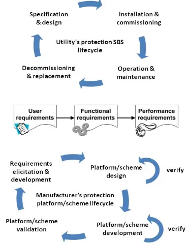
II. FUNCTIONAL AND USER REQUIREMENTS F PROTECTION SCHEME As any engineering system, adaptive prote through several life-cycle stages from development and from installation to d following a similar life-cycle to that protection schemes. Different stakeholder requirements that must be reflected in each The main stakeholders that define these req users (power utilities) and the suppliers (man adaptive protection scheme.
A. Protection Scheme Life-Cycle Stages From the user’s point of view, there ar cycle stages:
Scheme specification and design: this i case by case basis and draws heavily protection policy documentation. At th settings are calculated and the scheme lo Scheme installation and commissi
supplied by the manufacturer, which a type approved, are subjected to factory that emulate the physical scheme setup This is followed by installation in the site commissioning tests are cond electrical connections and corr functionality.
Scheme operation and maintenance: e operation during service is diagnosed causes of incorrect behavior. Some sch require revision should the primary s (e.g. reinforcement).
Scheme decommissioning and replacem of new schemes requires due considerat on existing systems. The evolving natur and secondary systems has resulted in and legacy protection schemes whic bespoke nature of delivering such sche concerns about sustainability of such ap of new smart grid developments and ad scheme implementations.
From the manufacturer’s point of view, f the relaying platform which ends up as part solution in a utility’s substation. In this cas equally important life-cycle stages. The main these stages and those of the utility are the requirements (Figure 1).
It is important to note that the last thr protection platform life-cycle involve rigoro outcomes against the originally specified r life-cycle stages are:
FOR AN ADAPTIVE
ection schemes go specification to decommissioning,
of conventional rs have specific h of these stages. quirements are the nufacturers) of the
e four main
life-is dealt with on a from the utility’s his stage detailed ogic is designed. ioning: schemes are assumed to be
y acceptance tests in the substation. substation where ducted to verify
rrect protection
erroneous scheme d to identify the heme settings may
system be altered
ment: introduction tion for the impact re of both primary a mix of modern ch highlights the
emes. This raises pproaches in light daptive protection
focus is placed on of a standard bay se, there are four n linkage between
specified scheme
[image:2.612.345.530.55.294.2]ree stages of the ous testing of the equirements. The
Figure 1 Protection scheme user and suppli User requirements elicitatio
functional requirements: work ensures delivering protection p are suitable. These requiremen further into performance requir boundaries of the protection sch Platform and scheme design:
devised to deliver the Considerations are also ma delivering the required fu platform.
Platform and scheme develop and software intensive enginee and integrates the elements required functionality wit requirements.
Platform and scheme validati conducted during the second that each of the elements requirements. Once these elem complete platform, it is valid being fit for purpose. A simi conducted to test schemes customer utility.
As manufacturer’s protection pla influence of the user requirements, little impact on what the platform order to tackle this, modern relayin flexibility such that new functions firmware upgrades or elaborate sche proposed in this paper builds up allows greater flexibility to integrate arrangements and the implementat without the need for an overhaul in p
ier life-cycle and requirements n and development of king closely with the user platforms and schemes that nts must also be developed rements that demarcate the
heme behavior.
platform architectures are functional requirements. ade into mechanisms of unctionality through the
pment: this is a hardware ring process which creates
necessary to deliver the thin the performance
ion: verification tests are and third stages to check created meet specified ments are integrated as a dated as a while and for ilar validation exercise is that are prepared for a
atforms reach maturity, the should they change, have m can inherently offer. In
ng platforms have built-in can be achieved through eme logic. The architecture
on this flexibility which e within existing substation
B. Adaptive Scheme Functional Requirements
Figure 2 shows a simplified functional flow of a generic adaptive protection scheme in order to achieve a suitable setting in response to a system event. Four main functions have been identified in order to deliver this at acceptable performance levels. These are: power system event detection and qualification, post-event evaluation of protection performance and post-event setting calculation and application.
Figure 2 Generic adaptive protection scheme operation
Events that have a potentially negative impact on the performance of a protection scheme must be detected through means of local or remote measurements or both. It is also necessary to qualify the extent of the event which is necessary to conduct the performance evaluation. Evaluating the performance of the protection scheme post-event is essential to ascertain the suitability of the applied settings. This function does not need to be conducted in real-time. It may be deemed sufficient to qualify the performance of the protection scheme under various operational events during the design stage which is then hardwired into the adaptive scheme. Should post-event scheme performance prove unsatisfactory after the evaluation process, a new setting is selected or calculated and then made active such that the scheme performance is brought to levels as specified by the original requirements outlined in the utility protection policy.
C. Adaptive Scheme User Requirements
Detailed functional requirements are highly dependent on the scheme in question and the application network. However, these serve to deliver on user requirements. The following is a brief list of the main user requirements that an adaptive protection scheme must adhere to. These should be measureable in such a way that they can be verified at different stage of scheme development:
Utilization of existing protection functions: the essence of adaptive protection functionality is altering the configuration of existing schemes (setting or scheme logic) in order to enhance their performance. For instance, a distance scheme can be complemented with overarching adaptive functions that improve its sensitivity to in-zone faults through reach alteration. Primary system conditions that sanction adaptive
behavior: as adaptive protection scheme do not offer a fit for all solution, it is necessary to define the events that instigate adaptive functionality and the nature of the required response. For instance, changing the topology of
a distribution network may require the regarding of overcurrent protection. Information about the new topology and its onset is therefore required.
Ease of integration with existing substation infrastructure: practical constraints posed by brown field sites and established protection practices require that adaptive schemes make most use of existing IEDs, computing and communications equipment. This manages risk of new technology as systems are decoupled and new technology introduced is limited to the adaptive functions as opposed to additional supporting infrastructure.
Minimum performance levels met by adaptive schemes: since these schemes are meant to alleviate performance shortfalls of existing schemes, they must satisfy minimum performance levels set by utility policy. Furthermore, any single failure mode of the adaptive scheme must not cause the any further deterioration of existing protection functions.
Standard interfaces for scheme configuration and diagnostics: adaptive protection schemes should remain faithful to the staple protection settings and scheme logic used for configuring expected scheme behavior. Furthermore signals that reflect adaptive behavior should be logged alongside disturbance records used to for post-event diagnostics. Information models adopted by the scheme should also adhere to common substation standards (e.g. IEC 61850).
All of the requirements developed above are fed in to the design process of the adaptive protection architecture proposed in following section. This aims to tackle some of the integration challenges of such new technologies and reduce their associated risks of their adoption.
III. ADAPTIVE PROTECTION ARCHITECTURE
One of the first and most critical steps in realizing an adaptive protection scheme is the design of a representative and functional architecture which reflects the developed requirements. This is an effective means of managing smart grid complexity through structural rigor [10]. The architecture will be referred to hereafter as the Adaptive Protection Architecture (APA). The APA serves the purpose of defining scheme elements’ connectivity, their interface and the scope of their operation. Furthermore, there are functions that the architecture delivers that are thought to be important to any adaptive scheme implementation. This greatly enhances technology maturity (de-risking) through components reuse.
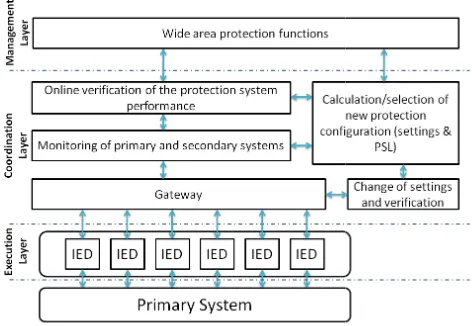
Figure 3 Adaptive protection architect A. APA Functional Layers
The extent of layer decoupling is determin system-wide impact of the layer’s functions. scope of each of the layer’s functions is affec of information required to infer the state of th based on which adaptive protection action is i At the execution layer, the status of th usually inferred from local voltage and curre or by remote measurements which are defin (e.g. digital current differential). Some lo information can also be used (e.g. breaker speaking, the execution layer encompasses m IEDs. The protection functions themselves conventional protection elements such as di overcurrent protection, low frequency deman etc. Execution layer functions usually r conditions in a matter of a few cycles d protection technology and function.
The functionality scope of the coord determined simply by status information t apparatus which has a direct impact on the p protection scheme to be adapted. Analogu aren’t usually of particular use but can association with thresholds to identify u conditions. Coordination layer functionalit status information to evaluate the ex performance under these conditions. Based on adaptive setting selection is initiated at response of coordination layer functions triggered nature which excludes fault conditi several seconds.
Finally, the management layer functions between the protection schemes in the fie protection functions in the control room. slower in responding to events compared layer and have no direct visibility of measurements. The management layer relies of a wide area nature such as synchrophas that are kept in phasor data concentrators system state. Advanced protection functions control room with the aid of managemen
ture
ned by the local or Furthermore, the cted by the extent he primary system
initiated.
he system can be ent measurements
ed by the scheme cal binary status r fail). Practically modern protection take the form of stance protection, nd disconnection, respond to fault depending on the
dination layer is that is related to
erformance of the ue measurements
still be used in unique operating ty relies on this xecution layer’s n that assessment,
this level. The is of an event ions and can take
s bridge the gap eld and advanced Those are much to the execution f the low level
on measurements sor measurements
(PDCs) to infer conducted in the nt layer interface
include diagnostic functions that e adaptive (an indeed general conven health. Management layer functions reside in the control room, but management layer functions that a system split points or zones that are stability margins or those that a interconnectors. This is in contrast [11], [12]. Simply handling all pro control-room as well as limiting t system integrity protection schemes need for a detailed understanding o performance of protection functions therein lies the importance function the APA.
B. Detailed APA Functional Descrip Each of the APA layers constitu essential to adaptive protection application and network to be prote implemented functions, maturity o achieved through the reuse of com higher level.
Figure 4 shows the interaction between the different functional ele layer and those of the adjacent layer the original functional requirements scheme shown and explained in sect necessary to detail a couple of performance evaluation and setting s If for example the reach of a dista the presence of a FACTS device (e.g presence of the device and its m detected by the coordination layer active distance reach settings can minimum reach requirements stipula This evaluation exercise can simply vs. line impedance calculations. Sho the scheme be violated, adaptive settings is sanctioned such that the offset.
The process of setting selection online setting calculations, where a each time the booster changes m network configuration. This setting affected protection IED. Alternative chosen from a pool of pre-calculate be activated by IED optical inputs local area network (LAN). This exam VI. to demonstrate the effectivenes
As shown in Figure 4, the scope encompasses several execution laye that coordination layer functions ov several protection IEDs that constitu scheme (e.g. distance schemes). O spectrum, the management layer additional supporting information f
evaluate the health of the ntional protection) scheme do not need to physically there could be regional are more suited to major defined by power flow or re demarcated by major t to suggestions found in otection settings from the the adaptive behaviour to s is impractical, hence the of the scope and required s and different levels. And nal abstraction offered by
ption
utes a number of functions operation. Although the ected heavily influence the of the technology can be mmon functions even at a
and flow of information ements of the coordination rs. This remains faithful to for an adaptive protection tion II. B. However, it is f the main functions – selection.
ance scheme is affected by g. a quad booster [13]), the mode of operation can be
and the suitability of the be evaluated against the ated by the utility’s policy. y take the form of a reach ould the minimum reach of e selection of protection e effect of the booster is
can be achieved through a new setting is calculated mode and in light of the
g is then written into the ely, the new setting can be ed settings groups that can or through the substation mple is reported in section s of the APA.
e of the coordination layer ers. This effectively means versee the performance of ute a substations protection On the other end of the r functions can provide
from a system wide-perspective or an override/enable signal which acts to prevent adaptive operation or indeed select a more appropriate setting, should this be of the primary system’s interest.
Figure 4 Detailed functional interactions at the coordination layer There are three main functions that reside at the management layer, all of which operate with system wide protection and primary system performance in mind. These are: contextual system evaluation, protection action and protection diagnostics. Information provided by phasor measurement units (PMU), for instance, can be used by the contextual system evaluation function to determine the onset of system instability, cascade trips or major changes in power flows due to intermittent energy resources. This information is then utilized by the protection action function. For example, in response to the onset of cascade trips, low frequency demand disconnection can be targeted to operate more optimally in the network area(s) closer to the frequency deviations. This can only be achieved with wider system visibility offered at the management layer level. Another example is related to system restoration conditions where protection schemes can act against the operator [14]. Protection action functions can disable adaptive behavior or set limits for the underlying schemes such that they are desensitized to non-fault phenomena during the restoration process. Finally the diagnostics function operates in a similar manner to that of the performance evaluation function but without direct intervention. Alarms are raised for system operator action. Global logs of the adaptive behavior can also be kept for post-event analysis. Communications between the substation and regional/national control rooms plays an important role enabling these functions.
The gateway serves the purpose of providing standard communications interfaces so that different scheme elements can be integrated more easily within the substation. Plant status information and setting change requests normally pass
through the gateway. Physically this can be existing substation gateways or protocol converters.
C. Centralized vs. Distributed Functionality
Since the APA is functionally abstract, implementing a physical scheme layout is a straightforward process of mapping functions onto physical devices. However, there are some unique physical implementation challenges from the view point of centralized and distributed layouts. Distributed functions pose a challenge since functions may need to be split over physical devices. Duplicating functions over several devices can be one way of tackling this challenge. However, there needs to be a coordinating authority through which a final adaptive setting selection decision is sanctioned.
To this end there are some functions that are suited to a certain physical layout as opposed to others. For instance, coordination functions that determine the system state and gather active setting indications from different relays are more suited to a centralized physical implementation. Conversely, active setting verification can be a distributed function, such that IEDs can verify whether they comply with the setting selection command and can raise a setting violation alarm if not.
IV. SUBSTATION INTEGRATION CONSIDERATIONS Considerations must be made for the communications system integration of adaptive protection schemes which constitutes several functional elements that can be from different vendors and can use different communication protocols. This challenge is being addressed by the development of substation communication gateways which can handle most of the commercial communication standards, including IEC 61850. The adaptive protection scheme can be implemented to use existing substation communication infrastructure. For example, coordination layer functions can monitor the system and change the protection settings through the communication gateway. To activate different settings groups using IEC 61850 requires writing to the SGCB control block over the LAN [15].
V. SCHEME VALIDATION MECHA The validation of protection schemes installation is of vital importance to malfunctioning, such as false tripping, protection, etc. Traditional protection schem validated through a series of type tests to dem protection scheme is capable of protecting th specified fault conditions.
Dynamic type tests are based on the use testing protective relays in order to simul behavior of the network during faults and t system performance [17], [18]. Dynamic typ used successfully for several years to va protection schemes, but the addition of ad protection makes the current validation techn
This can be explained by examining the d process. This process involves the set up relays or the protection scheme, and is then validation process which requires the simulat transients which can be:
Obtained from recorded or calculated w set can be used to playback a recorded generate a calculated waveform th transient of the network.
Calculated in real time: an RTDS is use network during normal and fault cond hardware in the loop (HIL) simulation. If the protection scheme is adaptive, the p are not fixed but can change as the prim changes. More effective validation mechani necessary. Knowledge of an adaptive sch blocks and their interactions, as shown in F the formulation of a validation methodolog adaptive protection schemes that adopt the A this paper. Each of the interfaces and components must adhere to the performance the requirements. However, since the APA implementation of an adaptive scheme, rep should only require the verification of these n
In terms of integrated scheme validation HIL simulation is considered a powerful met that. Dedicated testing environments can b purpose to investigate the impact of smart gr network and in turn the protection performa example adaptive scheme presented in sectio HIL testing environment for this purpose.
VI. EXAMPLE ADAPTIVE DISTANCE PROTE This section presents an example a protection scheme which modifies the r compensate for the presence of a qu transformer (QB) in the circuit. The impact o of distance protection has been discussed in proposed adaptive scheme. This scheme has and implemented in hardware while remai proposed APA.
ANISMS
s prior to their avoid undesired blinding of the mes are normally monstrate that the he network under
e of transients for late the dynamic est the protection pe tests have been alidate traditional daptability of the niques ineffective.
dynamic type test of the protection n followed by the tion of a series of
waveforms: a test d waveform or to hat represents a
ed to simulate the ditions to create a
protection settings mary system state
sms are therefore heme’s functional
igure 3 facilitates gy suitable for all APA presented in d the functional e levels set out in
enables modular placing functions new functions.
n, scenario-based thod of achieving be setup for this rid controls on the ance [9]. And the on VI. utilizes a
ECTION SYSTEM adaptive distance
reach settings to uadrature booster f QB on the reach
[13] along with a s been developed ining true to the
A. Adaptive Distance Scheme The adaptive protection scheme p [13] to overcome distance protecti implemented in a HIL configuration However, it is first important to features of this implementation.
The management layer function plans to operate QBs nationally in alluded to in [13], [19]. This effecti available from the coordinated contr control room to arm the adaptive sch mode change. This increases the r against spurious setting changes tha mode changes.
[image:6.612.337.537.596.717.2]The main coordination layer fun state acquisition, protection perf setting selection. The performance the system impedance data along assess the scheme performance characteristic description forms the c quantifies the impact of the QB mo characteristic description can be arrangements by simply modif coefficients. This reusability feature integration and facilitates technology The strategy of adapting the relay use of pre-verified settings groups. been used, although more than tw granularity is desired when the QB modes. In order to facilitate the scheme and components from differ one mapping of settings groups has of a reach error representation. Th from the performance evaluation fu from the physical relay’s settings im the scheme therefore involves an ou the same time allows greater flexib different manufacturers. The physi protection scheme in the HIL testing Figure 5. The coordination and ma are mapped to the ABB COM600 which communicates to the RTDS o execution layer functions reside in functional distance relay.
Figure 5 Adaptive distance scheme in a
proposed by the authors in ion under-reach has been n and is detailed later on. examine the architectural
ns in this case deal with a coordinated manner as ively uses the information roller situated in the grid’s heme in anticipation of QB robustness of the scheme at are not matched by QB
ctions perform the system formance evaluation and
evaluation function uses with the active setting to e. Furthermore, a QB core of this function which
de on distance reach. This applied to different QB fying the characteristic e enables easier substation y maturity.
y’s behavior is through the Two settings groups have wo can be used if greater is in boosting or bucking
integration between the rent manufacturers, one to s been abandoned in favor his means that the output function can be decoupled mplementation. Setting up utput stage mapping but at bility in using relays from cal setup of the adaptive g environment is shown in anagement layer functions 0 substation gateway [20] over DNP3 [21], [22]. The n the Alstom P446 multi
B. Primary System Model
[image:7.612.319.557.49.239.2]A section of the 400kV UK National modeled using RTDS as shown in Figure system parameters and substation designatio the appendix (section VIII. ) and [23]. A 2 installed on the line between HIGM and R manually controlled during the simulatio protection instrument transformers are on WBUR and HIGM at WBUR substation.
Figure 6 Simulated primary system C. Testing Results
Evaluation of conventional protection di performance has already been carried out in problem lies in zone under-reach when the Q the circuit. Figure 7 shows an example unde for a single phase fault applied on the RATS the QB is in bucking mode. An exhaust scenarios covering the full reach of the conducted to test the adaptive protection p results shown here illustrate a sample of the of the adaptive scheme.
[image:7.612.54.298.171.226.2]The performance evaluation function in change from setting group 1 (SG1 signal) t (SG2 signal) when the QB is engaged (QB shown in Figure 8. SG2 expands the zone cover the worst case scenario. The figure correct operation of the relay when the applied single phase fault is introduced to line.
Figure 7 Non-adaptive distance protection under-reac engaged for a single phase fault
l Grid has been e 6. The primary ons are detailed in 2750MVA QB is RATS and can be on. The distance
the line between
m
istance protection n [13]. The main QB is engaged in er-reach condition S-WILE line when tive set of fault
relay have been performance. The correct operation
nitiates a setting o setting group 2 Bypass signal) as reach to 20% to e also shows the
same previously the RATS-WILE
ch when the QB is
Figure 8 Correct adaptive distance protect engaged and a new setting g VII. CONCLUS This paper presented a flexi architecture fit for smart grid applic requirements-driven such that it manufacturer user and functional life-cycle stages of a scheme.
The architecture features function supporting functions which facilitate digital substations as well as the de by enabling their reuse.
Physical mapping of the archite has been demonstrated in a pro scheme targeting transmission c boosters. The correct performance demonstrated in a hardware-in-th procedure on a transmission system has been enabled through the imple quadrature booster control.
VIII. APPENDIX -RTDSMODEL D SETUP Primary system information inclu fault levels data is available in the statement [23]. The source impedan a 12 X/R ratio [24]. A 1000:1 and 4 ratios were used respectively. protection settings were used for th (i.e. 80% zone 1, 150% zone 2, 200ms and 600ms were used for zon Power swing blocking was enable functions were disabled.
tion operation when the QB is group is adapted
SION
ible adaptive protection cations. The architecture is
reflects utility and relay requirements at different
nally abstract adaptive and es integration into modern e-risking of new functions
cture’s adaptive functions ototype adaptive distance
circuits with quadrature of the scheme was also he-loop based validation m whose flexible operation
ementation of coordinated
DATA AND PROTECTION
uding line parameters and National Grid seven year nces were calculated using 400kV:110V CT and CVT Standard distance zone he conventional protection
[image:7.612.68.285.480.652.2]IX. REFERENCES
[1] S. K. Salman and I. M. Rida, “Investigating the impact of embedded generation on relay settings of utilities electrical feeders,” Power Delivery, IEEE Transactions on, vol. 16, no. 2, pp. 246 -251, Apr. 2001. [2] M. Khederzadeh and T. S. Sidhu, “Impact of TCSC on the protection of transmission lines,” Power Delivery, IEEE Transactions on, vol. 21, no. 1, pp. 80-87, 2006.
[3] S. Horowitz, D. Novosel, V. Madani, and M. Adamiak, “System-wide Protection,” Power and Energy Magazine, IEEE, vol. 6, no. 5, pp. 34-42, 2008.
[4] D. Tholomier, D. Paraiso, and A. Apostolov, “Adaptive protection of transmission lines,” in Power Systems Conference, 2009. PSC ’09., 2009, pp. 1-14.
[5] European Commission, “European SmartGrids Technology Platform - Vision and Strategy for European Electricity Networks of the Future.” 2006. [Online] Available: http://www.smartgrids.eu..
[6] E. M. Davidson, V. M. Catterson, and S. D. J. McArthur, “The role of intelligent systems in delivering the Smart Grid,” in 2010 IEEE Power and Energy Society General Meeting, 2010, pp. 1-6.
[7] T. Sauter and M. Lobashov, “End-to-End Communication Architecture for Smart Grids,” Industrial Electronics, IEEE Transactions on, vol. 58, no. 4, pp. 1218-1228, 2011.
[8] CIGRE, “Adaptive Protections and Control - Final Report,” 1995. . [9] P. McLaren et al., “Testing the ‘smarts’ in the smart T & D grid,” in
Power Systems Conference and Exposition (PSCE), 2011 IEEE/PES, 2011, pp. 1-8.
[10] K. Moslehi and R. Kumar, “A Reliability Perspective of the Smart Grid,” IEEE Transactions on Smart Grid, vol. 1, no. 1, pp. 57-64, Jun. 2010.
[11] Fangxing Li et al., “Smart Transmission Grid: Vision and Framework,”
IEEE Transactions on Smart Grid, vol. 1, no. 2, pp. 168-177, Sep. 2010. [12] N. Markushevich, “Cross-cutting Aspects of Smart Distribution Grid
Applications,” in 2011 IEEE Power and Energy Society General Meeting, 2011, pp. 1-8.
[13] I. F. Abdulhadi, G. M. Burt, A. Dysko, R. Zhang, and J. Fitch, “The evaluation of distance protection performance in the presence of Quadrature Boosters in support of a coordinated control strategy,” in
Developments in Power System Protection (DPSP 2010). Managing the Change, 10th IET International Conference on, 2010, pp. 1-5.
[14] T. S. Sidhu et al., “Protection issues during system restoration,” Power Delivery, IEEE Transactions on, vol. 20, no. 1, pp. 47-56, 2005. [15] “Communication networks and systems for power utility automation.
Basic information and communication structure. Abstract communication service interface (ACSI),” IEC Std 61850-7-2, 2010. [16] V. M. Catterson, E. M. Davidson, and S. D. J. McArthur, “Embedded
Intelligence for Electrical Network Operation and Control,” IEEE Intelligent Systems, vol. 26, no. 2, pp. 38-45, Apr. 2011.
[17] ALSTOM, “Network Protection and Automation Guide - Protective Relays, Measurement and Control.” 2011.
[18] “IEEE Guide for Power System Protection Testing,” IEEE Std C37.233-2009, pp. 1 -112, 2009.
[19] M. Belivanis and K. R. W. Bell, “Coordination of phase-shifting transformers to improve transmission network utilisation,” in Innovative Smart Grid Technologies Conference Europe (ISGT Europe), 2010 IEEE PES, 2010, pp. 1-6.
[20] ABB Oy, “ABB COM600 Station Automation - Product Guide,” 2009. [Online]. Available: http://www.abb.com.
[21] P. Forsyth, T. Maguire, and R. Kuffel, “Real time digital simulation for control and protection system testing,” in Power Electronics Specialists Conference, 2004. PESC 04. 2004 IEEE 35th Annual, 2004, vol. 1, pp. 329-335 Vol.1.
[22] RTDS Technologies, “RTDS Hardware Manual - GTNET Card.” 2009. [23] National Grid Electricity Transmission plc, “National Electricity
Transmission System (NETS) Seven Year Statement,” 2011. [Online]. Available: http://www.nationalgrid.com/uk/Electricity/SYS/current/. [24] N. Tleis, “Power Systems Modelling and Fault Analysis: Theory and
Practice. Newnes,” 2008.
X. BIOGRAPHIES
Ibrahim Abdulhadi obtained the MEng degree at the University of Strathclyde in 2007. He is currently studying for a PhD in power systems. His research interests include power system protection, real-time simulation and testing and communications applications for power systems.
Federico Coffele received the B.Eng and M.Eng from the University of Padova, Italy. He is a Research Associate within the Institute for Energy and Environment at the University of Strathclyde, Glasgow, U.K and he is studying towards his PhD degree. His research interests include power system simulation and power system protection.
Adam Dyśko (M’06) received the M.Sc. degree from the Technical University of Łódź, Poland, in 1990, and the PhD. degree from the University of Strathclyde, Glasgow, U.K., in 1998. Currently, he is a Lecturer in the Department of Electronic and Electrical Engineering, University of Strathclyde. His main interest areas are power system modeling and simulation, power system protection, and power quality.
Campbell Booth received the B.Eng. (Hons) and PhD. degrees from the University of Strathclyde, Glasgow, U.K. He is a Senior Lecturer within the Institute for Energy and Environment at the University. His research interests include power system protection and plant condition monitoring.