EXTENSION OF MARTIAN ORBITS USING CONTINUOUS LOW-THRUST PROPULSION
Pamela Anderson(1), Malcolm Macdonald(2), and Chen-wan L. Yen(3)
(1) Mechanical and Aerospace Engineering Department / JPL (JVSRP), University of Strathclyde
Glasgow G11XJ Scotland, +44 (0)141-548-5938, [email protected]
(2) Mechanical and Aerospace Engineering Department, University of Strathclyde Glasgow
G11XJ Scotland, +44 (0)141-548-2042, [email protected]
(3) JPL, 4800 Oak Grove Drive Pasadena CA 91109, (818)354-4899,
There has recently been significant interest in exploration of the Martian surface and atmosphere with a view to future human exploration. Thus missions must be developed which are responsive to these scientific goals. This work therefore develops novel orbits around Mars using continuous low-thrust propulsion to enable new and unique investigations of the red planet. This paper considers the use of continuous acceleration, using Solar Electric Propulsion, to alter the critical inclination of Highly Elliptical Orbits away from the conventional values, to any inclination required to optimally fulfill the mission objectives. This allows the spacecraft to spend a large amount of time over a region of interest as a result of apoareion dwell, thus allowing enhanced opportunities for remote sensing. In addition to this, the extension of existing circular Sun-synchronous orbits is considered as well as the development of Sun-synchronous Highly Elliptical Orbits, which force the ascending node angle to rotate at the same rate as the mean rotation of the Sun, whilst maintaining a constant argument of perihelion over the orbit. Thus, allowing simplification of the spacecraft thermal environment. Notably, we can enable these orbits using existing Electric Propulsion technology.
Keywords: Low-thrust propulsion, critical inclination, Sun-synchronous orbits.
1. Introduction
Exploration of Mars over the past three decades has allowed us to build a comprehensive and multidisciplinary view of Mars. Recently, Mars Express [1], Mars Odyssey [2, 3] and Mars Reconnaissance Orbiter [4] have delivered detailed information about the Martian surface geology and mineralogy, atmospheric composition and circulation, mineral composition, subsurface structure, radiation environment, and daily weather. However, each discovery about the Martian environment poses further questions. Additional significance has recently been placed upon the exploration of Mars with the reformulation of the Mars Exploration Program, which aims to assess both near-term mission concepts and longer-term foundations of program level architectures for future robotic exploration of Mars. With the goals of the program to discover whether life ever arose on Mars, characterize the climate of Mars and the geology of the surface, and prepare for human exploration, with the challenge of sending humans to orbit Mars in the decade of the 2030s. Thus, missions must be developed which are responsive to the scientific goals of both the National Research Council Planetary Decadal Survey [5], and the ESA Aurora Programme1, and extensive investigation is required into the Martian surface and
subsurface, lower atmosphere, winds and densities. This work therefore develops novel orbits around Mars to enable new and unique investigations.
Natural orbits typically used for remote sensing at Earth also exist at Mars, for example Sun-synchronous orbits, and Molniya-like orbits with fixed values of the ‘critical inclination’ [6]. The near constant illumination conditions of Sun-synchronous orbits, caused by the rotation of the orbit plane equalling that of the planet around the Sun, makes them especially suitable for remote sensing applications. These orbits have in the past been used for spacecraft orbiting Mars, such as Mars Odyssey [7], Mars Reconnaissance Orbiter [8], and Mars Global Surveyor [9]. Highly Elliptical Orbits (HEOs) with fixed ‘critical inclinations’ can also offer benefits for remote sensing of Mars, by allowing spacecraft to spend a large amount of time over a region of interest, as a result of apoareion dwell. The fixed inclinations of these orbits means there is no rotation of the apsidal line due to the concentration of mass around the equator of Mars, the fixed critical inclination of these orbits can however limit the potential applications.
The increased significance placed upon exploration of Mars means investigation is being conducted into a variety of Mars orbits to allow the best possible opportunities for remote sensing and for support of future Mars exploration [10]. This research therefore proposes new, novel orbits of Mars enabled using continuous low-thrust propulsion. Developments in electric propulsion systems are enabling a wide range of pioneering space applications, previously infeasible using conventional high-thrust propulsion. For example, recent research has considered the use of low-thrust propulsion for the extension of Earth Orbits, for example Sun-synchronous orbits to enable the free selection of orbit inclination and altitude [11]. The principle of using low-thrust propulsion to modify the perturbations has also been applied for the extension of HEOs around Earth, with particular focus on Molniya-like orbits [12, 13]. Extending this work further, Sun-synchronous HEOs have also been developed. For example, allowing a highly elliptical, Sun-synchronous orbit inclined at 90 degrees to the equator to allow a more simplified thermal environment [14].
Although the oblateness term, J2 is the dominating perturbation at Mars, this is not as dominating as J2at Earth, as the other first few harmonic coefficients are also strong for Mars, around 1-2 orders of magnitude lower than J2while, for Earth these are around 3-4 orders or magnitude lower. Thus, where previous work has enabled free selection of the critical inclination independent of the orbit semi-major axis and eccentricity, the magnitude of the first few harmonic coefficients at Mars, means these must be included when determining the critical inclination and so this value becomes dependent on the semi-major axis and eccentricity. Thus, for a particular semi-major axis and eccentricity two values of critical inclination exist for each orbit. The work presented herein extends these natural orbits using continuous low-thrust propulsion to create a new set of Martian orbits for improved remote sensing, while maintaining the zero change in argument of periapsis condition essential to Molniya-like orbits. This is achieved firstly by developing a general perturbations solution, which is validated using a special perturbations solution.
critical inclinations and thus no rotation of the apsidal line. The development of such novel orbits therefore creates additional observation opportunities of the surface and atmosphere of Mars, allowing more accurate observations for possible future human exploration. One such example would be to enable a Sun-synchronous HEO inclined at 90 degrees to allow improved studies of the Martian Polar Regions. Furthermore these new orbits may be of use for communication relay for human missions or UAVs or detailed mapping of the Martian surface. The transition from single spacecraft exploration of Mars to fleets of spacecraft both around Mars and on the Martian surface further highlights possible benefits of these novel orbits.
2. Spacecraft Motion About Mars
At Earth, the most dominant perturbation is the oblateness term, J2, with a value of J2 = 1.082627E-3. The harmonic coefficients J3 and J4 are around three orders of magnitude smaller than the J2 term with J3 = -2.53266E-6, and J4 = -1.61962E-6, and thus have negligible effect on the determination of the critical inclination. At Mars, the J2 perturbation is also dominant, with a value of J2 = 1.95545E-3. However, zonal harmonics through to J5 are only around two orders of magnitude lower than the J2 perturbation, with values of J3 = 3.14498E-5, J4 = -1.53774E-5, and J5 = 9.0793E-6, and so will have an effect on the determination of the critical inclination at Mars. Thus, unlike at Earth the computation of the critical inclination at Mars must include higher order terms and the values therefore become dependent on the semi-major axis and eccentricity of the orbit. This distinction highlights the unique contribution of this paper.
Considering the gravitational potential of a body
( )
( )
(
, ,)
,0 0
( , , )
n M
n m n m n m
n m R
U r C cos m S sin m P sin
r r
µ
β λ ∞ ∞ λ λ β
= =
⎛ ⎞
= ⎜ ⎟ +
⎝ ⎠
∑∑
(1)For a body possessing axial symmetry the influence of periodic effects (tesseral and sectorial harmonics) can be neglected for most orbits. The gravitational potential may be written as
0
( , ) 1
n M
n n
n
R
U r J P sin
r r
µ
β ∞ β
=
⎡ ⎛ ⎞ ⎤
= ⎢ − ⎜ ⎟ ⎥
⎝ ⎠
⎢ ⎥
⎣
∑
⎦ (2)( )
(
)
( )
(
)
( )
( )
(
)
( )
( )
( )
(
)
2 2 2 3 2 3 4 2 4 4 4 5 3 5 1( , ) [1 3 1
2 1
5 3
2 1
3 30 35
8 1
63 70 15
8 ....] M M M M R
U r J sin
r r
R
J sin sin
r R
J sin sin
r R
J sin sin sin
r
µ
β β
β β
β β
β β β
⎛ ⎞ = − ⎜ ⎟ − ⎝ ⎠ ⎛ ⎞ − ⎜ ⎟ − ⎝ ⎠ ⎛ ⎞ − ⎜ ⎟ − + ⎝ ⎠ ⎛ ⎞ − ⎜ ⎟ − + ⎝ ⎠ − (3)
Including perturbations to the order of J5 and using spherical triangle laws Eq. (3) becomes
( )
(
)
(
)
( )
(
)
( ) (
)
(
)
( )
(
)
( )
(
)
(
)
( )
(
)
( )
(
)
( ) (
)
(
)
2 2 20 2 3
3
3 3 3 4
4
2 2 4 4
4 5 5
5 5 3 3
5 6
( , ) 3 1
2
5 3
2
3 30 35
8
63 70 15
8 M p M M M R
U r U U J sin i sin
r r
R
J sin i sin sin i sin
r R
J sin i sin sin i sin
r R
J sin i sin sin i sin sin i sin
r
µ µ
β θ ω
µ θ ω θ ω
µ θ ω θ ω
µ θ ω θ ω θ ω
= + = − + −
− + − +
− − + + +
− + − + + +
(4)
This results in expressions for the perturbing accelerations in the radial, transverse and normal directions of
( ) (
)
( ) (
)
( ) (
)
( ) (
)
( ) (
)
2
3 2 2 3 2 2
2 4 3 5 2 4
7
2 2
3 5 4 5
( 12 15 ( 48 90 (6 (6 25 )
8
(80 420 7 (25 54 )))))
M
J M M M M
M M M M
R
R J r J rR sin i sin J r R J R sin i sin r J r J R
r
R sin i sin J r J R R sin i sin J r J R sin i sin
µ θ ω θ ω
θ ω θ ω θ ω
= − + + + − + + + − + + − + + + + (5)
(
) ( )
( ) (
)
( ) (
)
( ) (
)
( ) (
)
22 3 2 2
2 5 2 4
7
2 2
3 5 4 5
( 12 15 (24 60 5
8
(6(2 7 ) 7 (4 9 7 ))))
M
J M M M M
M M M M
R cos sin i
T J r R J rR sin i sin J r J rR R sin i sin
r
J r J R R sin i sin J r J R R sin i sin
µ θ ω
θ ω θ ω
θ ω θ ω
+ =− − + + + − + + − + + + + + (6)
( )
( ) (
)
( ) (
)
( ) (
)
( ) (
)
22 3 3 2
3 5 2 4
7
2 2
3 5 4 5
( 12 15 (24 60 5
8
(6(2 7 ) 7 (4 9 ))))
M
J M M M M
M M M
R cos i
N J r R J R sin i sin J r J rR R sin i sin
r
J r J R R sin i sin J r J R sin i sin
µ
θ ω θ ω
θ ω θ ω
=− − + + + − + +
− + + + +
3. Highly Elliptical Orbits
3.1 General Perturbations Solution
The equatorial bulge of Mars causes the argument of periapsis of the orbit to rotate; this effect is negated with orbits inclined at a critical inclination. The value of which is derived using the Gauss form of the Lagrange Planetary Equation for the rate of change of argument of periapsis [15].
(
)
2 3
1
tan
d r r r
Rcos T sin sin N
d e p p i
ω θ θ θ ω
θ µ µ
⎡ ⎛ ⎞ ⎤
= ⎢− + ⎜ + ⎟ ⎥− +
⎢ ⎝ ⎠ ⎥
⎣ ⎦ (8)
To obtain the value of the critical inclination Eqs. (5) - (7) are substituted into Eq. (8) and integrated analytically over one orbital revolution. Inserting orbital element values into the resulting formula, and setting this equal to zero, the resulting critical inclination is determined. For example, for a 12-hr orbit with a perihelion altitude of 800km and apogee altitude of 17,724km including perturbations to J4 results in critical inclinations of 63.29 degrees and 116.71 degrees. Increasing the perturbations to include J5 alters the critical inclination values to 63.24 degrees and 116.76 degrees, thus including the J5 perturbation results in difference of less than 0.1% from the J4 results, and can therefore be neglected in order to significantly reduce the solutions.
Equations (5) - (7) are simplified and low thrust terms added to allow the extension of the solutions. These low-thrust terms are added using the argument of periapsis control law derived from the variational equation, given in Eq. (8), by consideration of the sine and cosine terms in this equation. Locally optimal control laws maximize the instantaneous rate of change of the argument of perihelion, and provide the thrust orientation in analytical form [16]. The locally optimal control law gives the distinct position of the orbit where the sign of the thrust is required to switch direction. The combined perturbations up to J4 and low-thrust perturbations in each of the radial, transverse and out-of-plane directions are thus given by
( ) (
)
( ) (
)
( ) (
)
( ) (
)
( )
2
3 2 2 2
2 4 3 2 4
7
3 4
( 12 15 ( 48 (6(6 25 )
8
5 (16 35 )))) sgn cos
r M
J F M M M
M M r
R
R J r J rR sin i sin J rR sin i sin J r J R r
R sin i sin J r J R sin i sin F
µ θ ω θ ω
θ ω θ ω θ
+ = − + + + − + + −
⎡ ⎤
+ + + + + ⎣ ⎦
(9)
(
) ( )
( ) (
)
( ) (
)
( ) (
)
[
]
2
3 6
2 2
2 4 3 4
(3 2
(6 15 5 (3 7 ))) sgn
t
M
J F M
M M M t
R cos sin i
T J rR sin i sin
r
J r J R R sin i sin J r J R sin i sin F sin
µ θ ω θ ω
θ ω θ ω θ
+
+
= − +
− + + + + +
( )
( ) (
)
( ) (
)
( ) (
)
(
)
2 3 6 2 22 4 4 4
(3 2
(6 15 5 (3 7 ))) sgn
n
M
J F M
M M M n
R cos i
N J rR sin i sin
r
J r J R R sin i sin J r J R sin i sin F sin
µ
θ ω
θ ω θ ω θ ω
+ = − +
⎡ ⎤
− + + + + + ⎣ + ⎦
(11)
Equations (9) - (11) are again substituted into Eq. (8) and integrated over one orbital revolution. The resulting equation for the change in argument of perihelion over the orbit is made up of an Earth gravity term to the order of J4, a radial acceleration term and a transverse acceleration term, given by Eqs. (12) to (15).
( )
2( ) ( ) ( )
0 J Fr Ft
π
ω ω ω ω
Δ = Δ + Δ + Δ (12)
( )
(
)
(
)
(
)
(
)
(
)
( )
(
)
( )
(
)
( )
(
)
( )
( )
(
)
( )
(
)
( )
( )
2 2 2
2 2 2 2 2 2
2 4 2
4
4 2
2 2 2 2
4 4
2 2 2 2
4
2 2 2
3
3
( (384 1 135 4 5 20(32 1
512 1
52 63 ) cos 2 35 28 27 cos 4 )
10 ( 6 5 4 2 7 cos 2 7 2 9 cos 4 ) cos 2
16 1 ( 1 3 4cos 2 5 1 7 cos 4 ) csc si
M M J M M M e R
e a e J e J R a e J
a e e
e J R i e J R i
eJ R e e i e i
a e J R e i e i i
π ω
ω
Δ = − + − + + − +
− +
− + − +
+ − + + − + + +
+ − + − − − + + n
( )
ω ))(13)
( )
2 2 22
2 2
2 2
1 2 ( 2 2 4 1 1
1
1 1
1 ln 1 ln )
1 1
r r
F
e a F e e e Arctanh
e e
e e
e e e e
e e
ω
µ
⎡ − + ⎤
Δ = − + − − + ⎢ ⎥
⎢ − + ⎥
⎣ ⎦
⎡ − ⎤ ⎡ − + ⎤
− − + ⎢ ⎥+ − + ⎢ ⎥ ⎢ − + ⎥ ⎢ − + ⎥
⎣ ⎦ ⎣ ⎦ (14)
( )
t 4 2(
2 2)
t F
a e F
e
ω
µ
− +
Δ =−
(15)
acceleration are not equal, and no out-of-plane element is included, as this does not produce any reduction in the required acceleration magnitude; this is explained in more detail in [17].
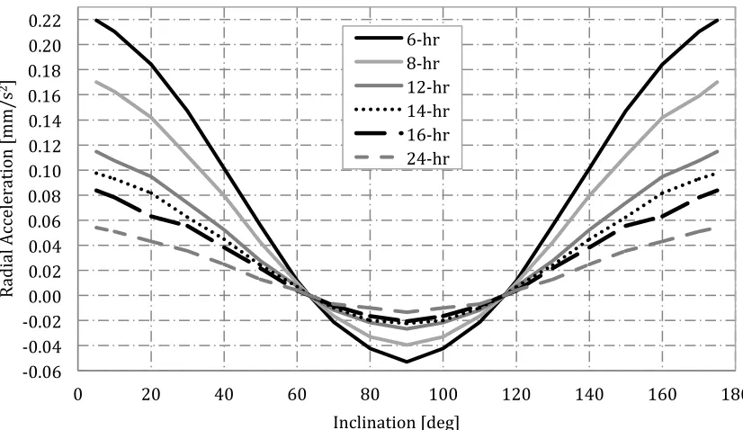
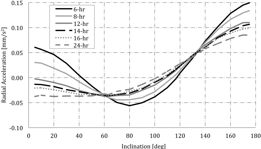
[image:7.612.98.511.236.475.2]The resulting acceleration magnitudes are shown for a variety of orbit periods between 6 and 24 hours to achieve inclinations between 5 degrees and 175 degrees for a constant periapsis altitude of 800km, to compensate for the drift in argument of perihelion caused by perturbations to the order of J4. The results are shown in Figure 1 - Figure 3 for an argument of perihelion value of 270 degrees. It is noted that the acceleration magnitude is dependent on the value assigned to the argument of periapsis, however considering the results for an argument of perihelion of 0 degrees shows a very small difference between the required acceleration from a value of 270 degrees.
Figure 1. Required radial acceleration, 800km perihelion orbits.
-‐0.06 -‐0.04 -‐0.02 0.00 0.02 0.04 0.06 0.08 0.10 0.12 0.14 0.16 0.18 0.20 0.22
0 20 40 60 80 100 120 140 160 180
R
ad
ia
l Ac
ce
le
ra
ti
on
[mm/
s
2]
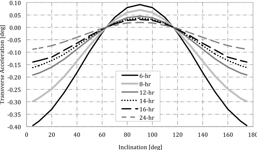
Figure 2. Required transverse acceleration, 800km perihelion orbits.
Figure 3. Total required acceleration for combined thrusting in radial and transverse axes,
800km perihelion orbits.
Figure 1- Figure 3 shows the curves of the required acceleration in the radial, transverse directions and the minimum total acceleration made up of unequal radial and transverse components to alter the critical inclination of the orbit to a wide range of possible values for the given orbit. It is shown that as expected, as the orbit period increases, the total acceleration
-‐0.40 -‐0.35 -‐0.30 -‐0.25 -‐0.20 -‐0.15 -‐0.10 -‐0.05 0.00 0.05 0.10
0 20 40 60 80 100 120 140 160 180
T
ra
ns
ve
rs
e
Ac
ce
le
ra
ti
on
[d
eg
]
Inclination [deg] 6-‐hr 8-‐hr 12-‐hr 14-‐hr 16-‐hr 24-‐hr
0.00 0.05 0.10 0.15 0.20 0.25 0.30 0.35 0.40 0.45 0.50
0 20 40 60 80 100 120 140 160 180
Ac
ce
le
ra
ti
on
[mm/
s
2]
magnitude decreases. Considering a 12-hr orbit with an inclination of 90 degrees requires a total acceleration of 0.05mm/s2. For a 1-ton spacecraft corresponds to an initial thrust level of 50mN, a thrust level well within the capabilities of current thruster technology. For example, NASA’s Solar Electric Propulsion Technology Application Readiness (NSTAR) thruster is capable of providing between 20mN and 94mN of thrust [18] and the QinetiQ T6 thruster, which is able to provide between 30mN and 210mN of thrust [19]. Thus, both thrusters are capable of providing the required thrust for this particular case.
It should be noted at this stage, that initial investigations into determining the fuel optimal solution suggest that significant savings in propellant mass could be gained from applying coast arcs to the orbit. This reduction appears to be larger than that gained by applying coast arcs to Earth orbits, it is thought that the higher order J terms at Mars have a more significant effect on the solution than at Earth, thus the difference between the locally optimal solution and the solution including coast arcs is more significant.
3.1 Special Perturbations Solution
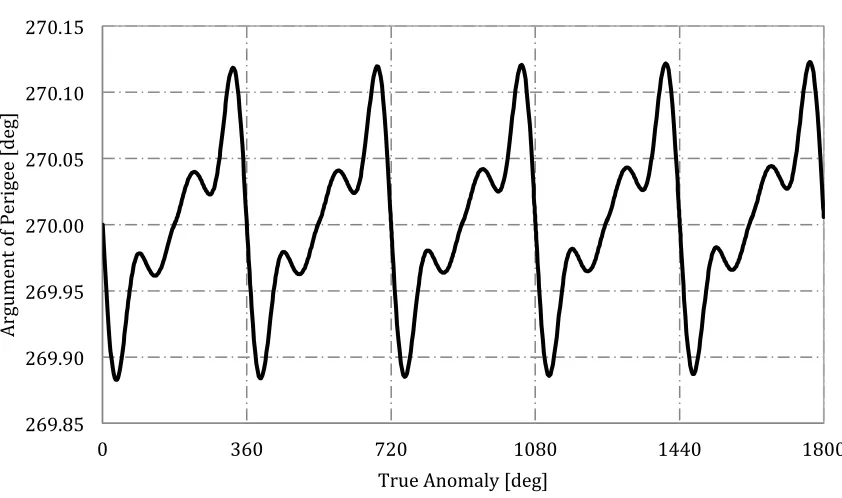
[image:9.612.95.510.438.679.2]Analytical solutions are verified using a special perturbations solution. This numerical model propagates the position of the spacecraft using a set of Modified Equinoctial Elements [21] using an explicit variable step size Runge Kutta (4,5) formula, the Dormand-Prince pair [22]. Results are shown for the semi-major axis, eccentricity and argument of periapsis for five revolutions of a 12-hr orbit with a 90 degree inclination in Figure 4 - Figure 6. These results show that although the orbital elements oscillate throughout the orbit, after one revolution, as expected, the element returns to the original value. It is noted that there is no change in the inclination or ascending node angle, thus these elements are not shown.
Figure 4. Variation of semi-major axis over five orbital revolutions.
12640 12660 12680 12700 12720 12740 12760 12780
0 360 720 1080 1440 1800
Se
mi
-‐ma
jo
r
Ax
is
[k
m]
.
Figure 5. Variation of eccentricity over five orbital revolutions
Figure 6. Variation of argument of periapsis over five orbital revolutions.
4. Sun-synchronous orbits
In addition to the extension of the critical inclination, continuous low-thrust propulsion can also be used to extend existing Sun-synchronous orbits to allow free selection of the orbit inclination
0.6685 0.6690 0.6695 0.6700 0.6705 0.6710 0.6715 0.6720
0 360 720 1080 1440 1800
Eccentr
icity
True Anomaly [deg]
269.85 269.90 269.95 270.00 270.05 270.10 270.15
0 360 720 1080 1440 1800
Ar
gu
me
nt
o
f P
er
ig
ee
[d
eg
]
[image:10.612.93.514.372.621.2]and altitude. A Sun-synchronous orbit requires the rate of change of the ascending node matches the motion of the Mean Sun (2π/686.429). The ascending node angle can also be described by the Gauss form of the variational equations using classical orbital elements [15]
( ) ( )
3 sin sin
d r
N dθ µp i θ ω
Ω= + (16)
Equation (11) is substituted into Eq. (16) and is again integrated over one revolution to give the change in ascending node over one orbit. In this case, as an out-of-plane acceleration is applied which is dependent on the argument of latitude, two solutions exist for an argument of perihelion equal to 0 degrees and 270 degrees, which give the maximum and minimum of the solution. This is again explained in more detail in [17]. This change in ascending node over one orbit is given by Eq. (17).
( )
2( ) ( )
0 J Fn
π
ΔΩ = ΔΩ + ΔΩ (17)
Where,
( )
(
)
( )(
)
(
)
(
)
( )( ) ( ) ( )
(
)
( ) ( ) ( ) ( )2 2
2 2 2 2 2 2
2 4 4
4
4 2
2 2 2
4 3
3
(cos ( 32 1 5 2 3 35 2 3 cos 2 )
32 1
5 (5cos 7 cos 3 ) cos 2 2 1 (cos 15cos 3 ) csc sin ) M
M M
J
M M
R
i a e J e J R e J R i
a e
e J R i i ae e J R i i i
π
ω ω
ΔΩ = − − + + + + +
− +
− + − − + +
(18)
( )
, 0 2( ) ( )
4 cos cot
n
n F
a F i
ω
ω µ
=
ΔΩ =− (19)
( ) ( )
( )
2
2 2 2
, 270 2
2 2 2
csc
(4 1 2 1 1
1 1 1
12 3 3 sin )
1 1 1
n
n F
a F i
e e e
e
e e e
eArcTanh eLog eLog
e e e
ω µ
ω
=
ΔΩ =− − + + − +
− +
⎡ − + ⎤ ⎡ − ⎤ ⎡ − + ⎤
− ⎢ ⎥− ⎢ ⎥+ ⎢ ⎥
− + − + − +
⎣ ⎦ ⎣ ⎦ ⎣ ⎦
(20)
( ) ( ) ( )
(
)
( )(
)
(
)
(
)
( ) ( ) ( ) ( )(
)
( ) ( ) ( ) ( ) 2 22 2 2 2 2
2 4
4
0 3 4 2
2 2 2 2
4 4
2 3
4 cos csc 1
( 3 (cos ( 32 1 5 2 3
2 (32 1 )
35 2 3 cos 2 ) 5 (5cos 7 cos 3 ) cos 2
2 1 (cos 15cos 3 ) csc sin ))
n
M M
M M
M
a F i
R i a e J e J R
a a e
e J R i e J R i i
ae e J R i i i
ω ω µ π µ π ω ω =
ΔΩ = + − − + + +
− + + + − + − − + + (21) ( ) ( ) ( )
(
)
( )(
)
(
)
(
)
(
)
( )2 2 2 2
270 3 2 2
4
2 2 4 2
2 2
2 2 2 2 2 2
2 2 4
2 2
4
1 1
( csc (4 1 2 1 12
2 ( 1 ) 1
1 1 1
3 3 )sin ( )
1 1 (32 1 )
3 (cos ( 32 1 5 2 3 5 2 3
35 2 3 cos 2
n
M M
M
e
a F i e e e eArcTanh
a e e
e e
eLog eLog
e e a e
R i a e J e J e J R
e J R i
ω µ π µ ω π = ⎡ ⎤ − − +
ΔΩ = − + + − + − ⎢ ⎥
− + ⎣ − + ⎦ ⎡ − ⎤ ⎡ − + ⎤ − ⎢ ⎥+ ⎢ ⎥ + − + − + − + ⎣ ⎦ ⎣ ⎦ − − + + + + +
+ +
(
2)
( ) ( ) ( ) ( )3
) 2− ae −1+e J RM(cos i +15cos 3 ) csci i sin ω ))
(22)
4.1 Circular Sun-synchronous Orbits
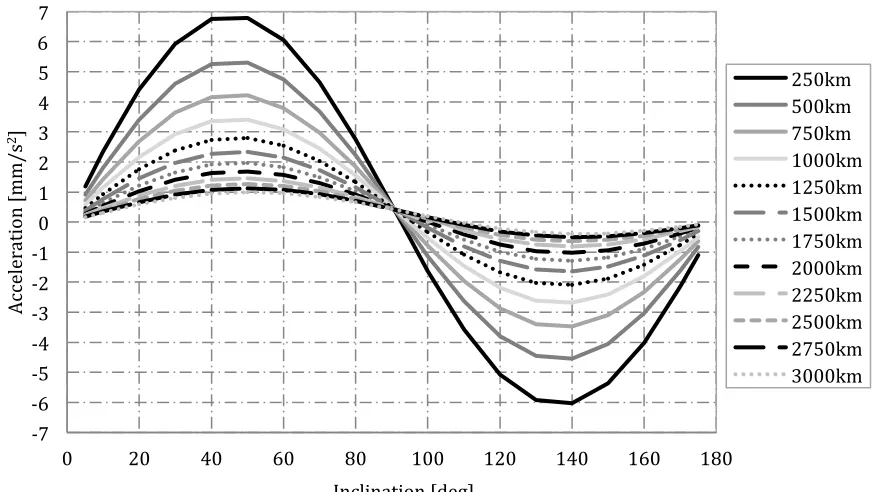
[image:12.612.73.499.186.292.2] [image:12.612.88.524.411.657.2]Firstly, considering the extension of circular orbits, the acceleration magnitude directed out of the orbit plane to achieve free-selection of the inclination for a range of orbit altitudes is given in Figure 7.
Figure 7. Normal acceleration required for extension of circular Sun-synchronous orbits, inclination range 5 degrees – 175 degrees.
-‐7 -‐6 -‐5 -‐4 -‐3 -‐2 -‐1 0 1 2 3 4 5 6 7
0 20 40 60 80 100 120 140 160 180
Ac ce le ra ti on [mm/ s
2]
Inclination [deg]
Figure 7 shows that circular Sun-synchronous orbits with free selection of the inclination and
altitude can be enabled using continuous out-of-plane acceleration. It is shown that orbits with inclinations around 90 degrees require acceptable accelerations, and the further the inclination drifts from this region, the level of acceleration required becomes infeasible using existing thruster technology.
4.2. Sun-synchronous Highly Elliptical Orbits
If HEOs are now considered, two conditions can be combined to obtain Sun-synchronous HEOs. These orbits use continuous out-of-plane acceleration to allow the ascending node angle to rotate to match the motion of the mean Sun, giving the Sun-synchronous condition. Combined radial and transverse acceleration are then used to compensate for the applied normal acceleration and maintain the zero change in argument of periapsis condition essential to Molniya like orbits. The radial, transverse, normal and the total acceleration magnitude to achieve Sun-synchronous HEOs of varying orbital period and inclination are given in Figure 8 - Figure 11 respectively for argument of perihelion values of 270 degrees for a constant periapsis altitude of 800km. It is noted that the same analysis is also conducted for an argument of periapsis value of 0 degrees, these results are however similar to those for an argument of periapsis value of 270 degrees, and so are not included in this paper. Comparison of these results shows that the value of the argument of perihelion does not significantly affect the level of acceleration required to achieve Sun-synchronous HEOs as these accelerations are of the same order of magnitude.
Figure 8. Radial acceleration to achieve Sun-synchronous HEOs of varying period and inclination, ω = 270 degrees.
-‐0.10 -‐0.05 0.00 0.05 0.10 0.15
0 20 40 60 80 100 120 140 160 180
R
ad
ia
l Ac
ce
le
ra
ti
on
[mm/
s
2]
Inclination [deg] 6-‐hr
[image:13.612.101.517.388.626.2]Figure 9. Transverse acceleration to achieve Sun-synchronous HEOs of varying period and inclination, ω = 270 degrees.
Figure 10. Normal acceleration to achieve Sun-synchronous HEOs of varying period and inclination, ω = 270 degrees.
-‐0.30 -‐0.25 -‐0.20 -‐0.15 -‐0.10 -‐0.05 0.00 0.05 0.10 0.15
0 20 40 60 80 100 120 140 160 180
T
ra
ns
ve
rs
e
Ac
ce
le
ra
ti
on
[mm/
s
2]
Inclination [deg]
6-‐hr 8-‐hr 12-‐hr 14-‐hr 16-‐hr 24-‐hr
-‐0.20 -‐0.10 0.00 0.10 0.20 0.30 0.40 0.50 0.60
0 20 40 60 80 100 120 140 160 180
N
or
ma
l Ac
ce
le
ra
ti
on
[mm/
s
2]
Inclination [deg]
[image:14.612.102.515.381.619.2]Figure 11. Total acceleration magnitude to achieve Sun-synchronous HEOs of varying period and inclination, ω = 270 degrees.
From Figure 11, considering a 12-hr orbit with an inclination of 90 degrees requires a total acceleration magnitude of 0.31mm/s2 and 0.15mm/s2 for argument of perihelion values of 0 degrees and 270 degrees respectively. Corresponding to initial thrust levels of 310mN and 150mN respectively for a 1-ton spacecraft. Although these thrust levels are higher than that required for the orbits excluding the Sun-synchronous condition, these levels are still within the capabilities of current thrusters. For example, the High Power Electric Propulsion (HiPEP) thruster which has undergone ground testing is capable of providing a maximum of 670mN [23] and test data from the Nuclear Electric Xenon Ion System (NEXIS) has also shown a maximum thrust level of 476mN [24].
4.3. Special Perturbations Solution
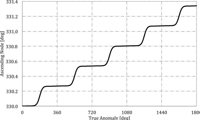
Similarly to the extension of the critical inclination solutions, Sun-synchronous HEOs are verified using numerical simulations. Figure 12 and Figure 13 show the evolution of the argument of periapsis and ascending node are as expected over five orbital revolutions, for a 12-hr, 90 degree inclination Sun-synchronous orbit. With the change in argument of perihelion shown to be negligible over the orbit and a change in ascending node angle of around 0.5 degrees per day.
0.00 0.10 0.20 0.30 0.40 0.50
0 20 40 60 80 100 120 140 160 180
Ac
ce
le
ra
ti
on
[mm/
s
2]
Inclination [deg]
Figure 12. Variation of argument of periapsis over five orbital revolutions, Sun-synchronous orbit.
Figure 13. Variation of ascending node over five orbital revolutions, Sun-synchronous orbit.
6. Conclusion
269.85 269.90 269.95 270.00 270.05 270.10 270.15
0 360 720 1080 1440 1800
Ar
gu
me
nt
o
f P
er
ig
ee
[d
eg
]
True Anomaly [deg]
330.0 330.2 330.4 330.6 330.8 331.0 331.2 331.4
0 360 720 1080 1440 1800
As
ce
nd
in
g
N
od
e
[d
eg
]
[image:16.612.99.509.394.641.2]Continuous low-thrust propulsion has been shown to enable novel orbits around Mars for enhanced remote sensing. This applied acceleration is used to extend the critical inclination from the conventional values to any inclination required to fulfill the mission goals. For example, to enable a 12-hr, 90 degree inclination orbit an acceleration of 0.05mm/s2 is required, a modest value of acceleration which is achievable using existing Electric Propulsion technology. Additional out-of-plane acceleration can also be added to allow extension of Sun-synchronous orbits around Mars. This can be applied to both circular and Highly Elliptical Orbits, which allow the rotation of the ascending node angle to match that of the Mean Sun whilst maintaining a constant argument of perihelion over each orbital revolution. Although Sun-synchronous orbits require higher acceleration than simply altering the critical inclination, the acceleration values are within the limits of current thruster technology.
7. References
1. Chicarro, A. F., Witasse, O. G., and Rossi, A. P. "Mars Express: Summary of Scientific Results." 2009.
2. Christensen, P. R., Jakosky, B. M., Kieffer, H. H., Malin, M. C., McSween, H. Y., Nealson, K., Mehall, G. L., Silverman, S. H., Ferry, S., Caplinger, M., and Ravine, M. "The Thermal Imaging System (THEMIS) for the Mars 2001 Odyssey Mission," Space Science Reviews Vol. 110, No. 1, 2004, pp. 85-130.
3. Varghese, P. "2001 Mars Odyssey Mission."
4. Zurek, R. W., and Smrekar, S. E. "An overview of the Mars Reconnaissance Orbiter (MRO) science mission," Journal of Geophysical Research Vol. 112, No. E05S01, 2006. 5. Squyres, S. "Vision and Voyages For Planetary Science in the Decade 2013-2022." 2011. 6. Liu, X., Baoyin, H., and Ma, X. "Five Special Types of Orbits Around Mars," Journal of
Guidance, Control and Dynamics Vol. 33, No. 4, 2010, pp. 1294-1301.
7. Smith, J. C., and Bell, J. M. "2001 Mars Odyssey Aerobraking," Journal of Spacecraft and Rockets Vol. 42, No. 3, 2005, pp. 406-415.
8. Jai, B., Wenkert, D., Hammer, B., Carlton, M., Johnston, D., and Halbrook, T. "An Overview of Mars Reconnaissance Orbiter Mission and Operations Challenges," AIAA Space 2007 Conference & Exposition. Long Beach, California, 2007.
9. Lyons, D. T., Beerer, J. G., Esposito, P., and Johnston, D. M. "Mars Global Surveyor: Aerobraking Mission Overview," Journal of Spacecraft and Rockets Vol. 36, No. 3, 1999, pp. 307-313.
10. Macdonald, M., Mckay, R., Vasile, M., Bosquillon de Frescheville, F., Biggs, J., and McInnes, C. R. "Low-Thrust Enabled Highly Non-Keplerian Orbits in Support of Future Mars Exploration," Journal of Guidance, Control and Dynamics Vol. 35, No. 5, 2011, pp. 1396-1411.
11. Macdonald, M., McKay, R., Vasile, M., and Frescheville, F. B. d. "Extension of the Sun-Synchronous Orbit," Journal Guidance Control and Dynamics Vol. 33, No. 6, 2010, pp. 1935-1940.
12. Anderson, P., and Macdonald, M. "Extension of Highly Elliptical Earth Orbits using Continuous Low-Thrust Propulsion," Journal Guidance Control and Dynamics, 2011. 13. Anderson, P., and Macdonald, M. "Continuous Remote Sensing of Polar Regions from a
14. Anderson, P., and Macdonald, M. "Sun-Synchronous Highly Elliptical Orbits uisng Low-Thrust Propulsion," Journal of Guidance, Control and Dynamics, Submitted August 2012.
15. Fortescue, P., Stark, J., and Swinerd, G. Spacecraft Systems Engineering. England: John Wiley & Sons Ltd. Chichester, West Sussex, England, 2003. 94.
16. Macdonald, M., and McInnes, C. R. "Analytical Control Laws for Planet-Centered Solar Sailing," Journal of Guidance, Control and Dynamics Vol. 28, No. 5, 2005, pp. 1038-1048.
17. Anderson, P., and Macdonald, M. "Extension of Highly Elliptical Earth Orbits using Continuous Low-Thrust Propulsion," Journal of Guidance, Control and Dynamics, Accepted November 2011.
18. Brophy, J. R., Kakuda, R. Y., and Polk, J. E. "Ion Propulsion System (NSTAR) DS1 Technology Validation Report."
19. Wallace, N. C. "Testing of The QinetiQ T6 Thruster in Support of the ESA BepiColombo Mercury Mission," 4th International Spacecraft Propulsion Conference (ESA SP-55). Cagliari, Sardinia, Italy, 2004, 2-4 June 2004.
20. Becerra, V. M. "PSOPT Optimal Control Solver User Manual." University of Reading, 2010.
21. Walker, M. J. H., Ireland, B., and Owens, J. "A set of Modified Equinoctial Orbital Elements," Celestial Mechanics Vol. 36, 1985, pp. 409-419.
22. Dormand, J. R., and Prince, P. J. "A family of enbedded Runge-Kutta formulae," Journal of Computational and Applied Mathematics and Statistics Vol. 6, No. 1, 1980, pp. 19-26. 23. Forster, J. E., Haag, T., Patterson, M., Williams, G. J., Sovey, J. S., Carpenter, C.,
Kamhawi, H., Malone, S., and Elliot, F. "The High Power Electric Propulsion (HiPEP) Ion Thruster," 40th Joint Propulsion Conference and Exhibit. Fort Lauderdale, FL, 2004, 11-14 July 2004.