Effect of dimerization on the field-induced birefringence in ferrofluids
Jacek Szczytko,1,*Nataˇsa Vaupotiˇc,2,3Mihail A. Osipov,4Karolina Madrak,5and Ewa G´orecka5 1Institute of Experimental Physics, Faculty of Physics, University of Warsaw, Hoza 69, 00-681 Warsaw, Poland
2Department of Physics, Faculty of Natural Sciences and Mathematics, University of Maribor, Koroˇska 160, 2000 Maribor, Slovenia
3Jozef Stefan Institute, Jamova 39, 1000 Ljubljana, Slovenia
4Department of Mathematics and Statistics, University of Strathclyde, 26 Richmond Street, G1 Glasgow, UK 5Department of Chemistry, University of Warsaw, ˙Zwirki i Wigury 101, 02-089 Warsaw, Poland
(Received 21 April 2013; published 28 June 2013)
The magnetic-field-induced birefringence in a ferrofluid composed of spherical cobalt nanoparticles has been studied both experimentally and theoretically. The considerable induced birefringence determined experimentally has been attributed to the formation of chains of nanoparticles. The birefringence has been measured as a function of the external magnetic field and the volume fraction (f) of nanoparticles. It is quadratic inf as opposed to the Faraday effect, which is linear inf. Experimental results agree well with the theoretical model based on a simple density functional approach. For dilute solutions the experimental results can be explained by assuming that only dimers of nanoparticles are formed while the concentration of longer chains is negligible.
DOI:10.1103/PhysRevE.87.062322 PACS number(s): 82.70.−y, 75.75.−c, 78.20.Ls, 78.67.Sc
I. INTRODUCTION
Magnetic fluids [1–4], called also ferrofluids, are colloids that consist of ferromagnetic nanoparticles dispersed in a liquid host. During the past four decades ferrofluids have been under intensive study, since they can be used in several mechan-ical and electromechanmechan-ical devices. Currently they attract a particular interest because of their biological applications. Ferrofluids can easily be manipulated by an external magnetic field, and thus they can be used for precise drug delivery and in hyperthermia applications (see, e.g., [5,6] and references therein). They also have large potential for applications in optical devices [7], such as tunable beam splitters [8], tunable gratings [9], interferometers [10], and optical logic devices [11]. They are also used in fiber optics including optical fiber modulators, optical filters, and fiber sensors, in which the ferrofluid is used as a fiber cladding or coating [12,13]. Recently, the fabrication of the magnetic-fluid core fiber was reported as well [14].
The most common optical effects which may be tuned by an external magnetic field are optical activity and birefringence. Both induced optical activity (Faraday rotation) and induced birefringence (Cotton-Mutton effect) of ferrofluids have been studied extensively. The induced birefringence results from the anisotropic shape of nanoparticles or/and formation of chains of nanoparticles. If birefringence is due to the anisotropic shape of particles, it increases linearly with increasing vol-ume fraction of nanoparticles, as has already been shown experimentally for cobalt ferrite [15], maghemite [16], nickel ferrite [17,18], and magnetite [19] ferrofluids. Nanoparticles can also form chains. Chain formation presents another source of anisotropy in the ferrofluid, but if nanoparticles have anisotropic shape, chains affect the birefringence only when the volume fraction of nanoparticles is high enough [20]. However, if the ferrofluid is a suspension of spherical cobalt nanoparticles in organic liquids such as toluene or cyclohexane [21,22], the only source of anisotropy is due to chains of
*Corresponding author: [email protected]
nanoparticles. While the formation of particle chains has been discussed already in 1970 [23], it has been only recently confirmed by direct experimental observation [24–26]. It has been suggested that the chain length increases with increasing magnetic field [27–31], the effect being important only if the volume fraction of nanoparticles is sufficiently high. In dilute systems of nanoparticles of the size of the order of 10 nm one can expect only a small volume fraction of two-particle dimers [32]; their volume fraction increases with increasing magnetic field [33,34]. Besides being theoretically predicted, particle chains in very dilute samples were obtained also by Monte Carlo numerical studies [35].
In this paper we present measurements of magnetically induced birefringence in ferrofluids composed of spherical cobalt particles dispersed in cyclohexene. Very dilute solutions with volume fraction of nanoparticles (f) lower that 10−4 have been studied. The dependence of birefringence on the magnitude of the external field and on the concentration of nanoparticles is investigated. Experimental results can be explained by the formation of nanoparticle dimers, thus confirming the theory. Both theory and experiment show that the induced birefringence increases as f2, while in the case of nanoparticles with anisotropic shape, the birefringence increases linearly withf.
II. THEORETICAL CONSIDERATIONS A. Volume fraction of dimers
To estimate the volume fraction of dimers we use the simple density functional approach [23,32–34]. The concentration of dimers depends on the competition between the reduction in energy due to the formation of a dimer and the reduction in entropy associated with the pair formation. When a dimer is formed, the energy reduces by kBT S0, where in the case of very weak external magnetic fields
S0=ln
1 3U03e
2U0(1−e−U0)
and in the case of a strong external magnetic field
S0 =ln
1 3U2
0
e2U0
. (2)
The parameterU0is the ratio between the magnetic interaction energy of two magnetic dipoles and the thermal energykBT:
U0=
μ2μ 0 4π d3k
BT
,
whereμis the magnetic moment of one nanoparticle,μ0is the magnetic constant, andd is the distance between the dipole centers, which we shall take to be equal to the average diameter of nanoparticles including the surface organic coating.
The general expression for the free energy (F) of a suspension including chains withN nanoparticles is
F kBT
= −∞
N=1
(N−1)S0ρ(N)+
∞
N=1
ρ(N)[lnρ(N)−1]
+λ
∞
N=1
Nρ(N).
The first term presents the reduction in free energy due to the formation of a chain withN particles. The reduced number densityρ(N) is the number density multiplied by the volume of one nanoparticle. The second term is the reduction in entropy due to the formation of the chain. The last term with the Lagrange multiplierλenforces the condition that the number of nanoparticles is constant:
∞
N=1
Nρ(N)=ρ0, (3)
whereρ0 is the reduced number density of all nanoparticles. The minimization condition∂F /∂ρ(N)=0 gives
ρ(N)=exp{(N−1)S0−λN}. (4)
In dilute solutions and for small nanoparticles with radius up to 10 nm only chains of two particles need to be considered, so the condition(3)reads
ρ(1)+2ρ(2)=ρ0. (5)
When Eq.(4)is used in Eq.(5), one obtains the condition for
λ:
e−λ= −1+
1+8ρ0eS0
4eS0 ≈ρ0,
where we have assumed very low number densities of nanoparticles: 8ρ0eS01. Finally, the number density of the
dimers is
ρ(2)≈ρ02eS0. (6)
Expressing the result(6)in terms of the volume fraction of all particles (f) and the volume fraction of dimers [f(2)] and using Eq.(1)we find the volume fraction of dimers in a zero external field:
f(2)≈2f2e
2U0
3U3 0
(1−e−U0) (7)
and the volume fraction of dimers in a strong external magnetic field:
f(2)≈2f2e
2U0
3U02. (8)
In the case of nanoparticles with a diameter (including the surfactant coating) ofd =13 nm with a magnetic moment of 6×10⁴ Bohr magnetons we findU
0=3.4 (at T =300 K). If the volume fraction of nanoparticles is of the order of
f ∼10−4then one can expect 1 or 2 dimers per 103monomers at zero field and approximately 5 dimers per 103 monomers in a strong external magnetic field. From Eq. (4) we can also calculate the number density of three-particle chains and confirm that it is negligibly small.
III. DIELECTRIC TENSOR OF A FERROFLUID Optical properties of composite materials can be expressed by the effective dielectric tensor εeff, which includes infor-mation on the optical properties of the host and inclusion (nanoparticles). Although the mixture is also optically active [22,36–38] we shall focus only on birefringence, and the off-diagonal terms in the dielectric tensor can be neglected. When calculating the expression for the dielectric tensor we have to include the possibility of the spherical nanoparticles forming chains. While these chains are not significant in explaining the Faraday rotation in dilute solutions of nanoparticles, they have a huge effect on the birefringence, because of their anisotropic shape.
For an external field applied along thezaxis the effective dielectric tensor is written as
εeff =
εeff
1 0 0
0 εeff
1 0
0 0 εeff2 .
The host is optically isotropic in a zero external field and it becomes birefringent in a nonzero external magnetic field. The dielectric tensor of the host,εhost, is thus expressed as
εhost=
εh1 0 0
0 εh1 0
0 0 εh2
.
The dielectric tensor of the Co nanoparticles (inclusion) is anisotropic since particles are magnetized having internal magnetic field already built-in. The elements of the dielectric tensor are obtained from the Drude model. However, the effect of the internal and external magnetic field on the diagonal elements of the dielectric tensor expressed in the eigenframe of a nanoparticle turns out to be negligible. The theoretically predicted birefringence which results from the anisotropy of spherical nanoparticles due to the external magnetic field is several orders of magnitude smaller than the measured value. Therefore we assume that the diago-nal elements of the dielectric tensor of inclusion are all equal to
εi=1+
i(ωpτ)2
where ω is the frequency of light, ωp is the plasma fre-quency, and τ is the characteristic lifetime of momentum relaxation.
Since we are interested in birefringence only, we can also neglect the off-diagonal terms, which are always very small compared to the diagonal terms and are important only when Faraday rotation is considered.
We shall thus attribute the birefringence solely to the formation of nanoparticle chains. In the first approximation a short chain of nanoparticles can be described as an inclusion of ellipsoidal shape, the ratio between the long and the short axis being simply the number of particles in the chain. To find the effective dielectric tensor we use the fact that in our system the volume fraction of nanoparticles is very small, of the order of 10−4 or less. As shown in the previous section only dimers can be expected at such low densities. The effective dielectric tensor of the mixture can then be approximated as
εeff =εhost+ρ(2) ε0
αiθ,φ,
where αiθ,φ is the dimer polarizability averaged over all possible orientations of dimers.
For a dimer with its long axes along the external magnetic field the polarizability is expressed as
αi=
α⊥ 0 0
0 α⊥ 0
0 0 α
=
αI+α
3
1 0 0
0 1 0
0 0 −2
, (9)
withα=(2α⊥+α)/3,α=α⊥−α , and
α⊥= (εi−εh) εh+(εi−εh)L⊥
ε0εhVi
and
α = (εi−εh) εh+(εi−εh)L
ε0εhVi,
whereViis the volume of a dimer andεhis the average value of εh1,2.L⊥ andL are the depolarization ratios that satisfy the conditionL +2L⊥=1.
The average polarizabilityαiθ,φis calculated as
αiθ,φ= 1
Z
1 4π
1
−1
dcosθ 2π
0
dφ RαiRTexp(xcosθ),
whereRis the rotation matrix andZ= −(sinhx)/xis the sta-tistical sum withx =μ(2)Bext/kBT andμ(2) being the mag-netic moment of a dimer. Performing the integration one finds
αiθ,φ=αI +
α
3
p1 0 0
0 p1 0
0 0 −2p1
with
p1=1−3
L(x)
x ,
whereL(x)=cothx−1/x is the Langevin function. By defining the volume density of dimers asf(2)=ρ(2)Vi the following expressions for the elements of the effective dielectric tensor are found:
ε1eff=εh1+f(2)εh(εi−εh)
[−2+3L⊥+p1(1−3L⊥)]εi−[1+3L⊥+p1(1−3L⊥)]εh 3[L⊥(εi−εh)+εh][2L⊥(εi−εh)−εi]
(10)
and
εeff2 =εh2+f(2)εh(εi−εh)
[−2+3L⊥−2p1(1−3L⊥)]εi+[−1−3L⊥+2p1(1−3L⊥)]εh 3[L⊥(εi−εh)+εh][2L⊥(εi−εh)−εi]
. (11)
The result given by Eqs. (10) and (11) is the same as the result derived by Rasa [39,40] for solutions of particles with anisotropic shape, if the limit of a small volume fraction of particles is considered.
The dielectric anisotropyε=εeff2 −εeff1 is
ε=εh2−εh1
+f(2) εhp1(εi−εh) 2(3L
⊥−1) [L⊥(εi−εh)+εh][2L⊥(εi−εh)−εi]
. (12)
The anisotropy is zero if there is no external field (p1=0,εh1=εh2) and it equals the anisotropy of the host material if (i) the particles are spherical (L⊥=1/3), (ii) there are no dimers [f(2)=0], (iii) and the inclusion has the same dielectric constant as the host [(εi−εh)=0].
The elements of the dielectric tensor are related to the ordinarynoand extraordinarynerefractive indices and in the limit of small birefringence n=ne−no it can be shown
that
n≈1
2 Re(ε)
√ εh
.
The birefringence due to the dimers is thus
n≈ 1
2f(2)
p1 √ε
h
×Re
(εi−εh)2(−3L⊥+1) [L⊥(εi−εh)+εh][2L⊥(εi−εh)−εi]
. (13)
Since n is proportional to the volume fraction of dimers,
f(2), it is thus proportional to f2eS0 [see Eq. (6)], i.e., to
IV. EXPERIMENTAL SETUP AND MEASUREMENTS Cobalt nanoparticles were obtained by the high-temperature decomposition of an organometallic precursor— octacarbonyldicobalt, Co2(CO)8—in ao-dichlorobenzene so-lution under inert (Ar) atmosphere. To prevent particle aggre-gation organic surfactants, trioctylphosphane oxide (TOPO) and oleic acid (OA), were present. The diameter of obtained particles was controlled by the TOPO/OA ratio used in the synthesis. Synthesized Co nanoparticles were precipitated in anhydrous acetone and redissolved in a nonpolar solvent such as cyclohexane. Particles were spherical, as shown from high-resolution transmission electron microscopy (TEM). The metal core diameter was estimated by small-angle x-ray scattering (SAXS) from particles dissolved in cyclohexane. The BrukerNanoStar x-ray system with NANOFIT software was used. The size of nanoparticles was also checked by TEM. The average diameter of studied particles was 11 nm; the size distribution evaluated from the scattering data under the assumption of a Schultz size distribution was±1 nm.
For the magneto-optical measurements cyclohexene mix-tures of different concentration of nanoparticles were prepared. The concentration of nanoparticles was determined by as-suming that UV absorption increases linearly with particle concentration.
The setup for measurements of birefringence consisted of a light source (a He-Ne laser of five lines with wavelengths of 543, 594, 604, 612, and 633 nm), an optical chopper with a defined frequency to modulate the beam (to measure the total light intensityITotwith a lock-in amplifier), and a set of filters to reduce the intensity of light at the detector. The light propagated through the first polarizer P1 and then through the sample placed in the induction coil, generating a homogenous magnetic field up to 0.4 T. The light transmitted through the sample was modulated by the photo-elastic modulator (PEM), working at a basic frequency=50 kHz and maximal retardation λ/4. Finally, the light passed through a linear polarizer P2. Polarizers P1 and P2 were crossed and their axes were at 45 degrees to the PEM axis. Transmitted light was detected by a silicon diode and the output signal was analyzed by using a lock-in amplifier.
Quantitative information about optical properties of a sample is given by the ratio of the signal intensities at
(I1) and 2 (second harmonic,I2). The birefringence is given by
n=λ0R
2π l,
whereλ0is the wavelength in vacuum,lis the sample length, and the measured quantityRis given by
R=arctan
I1 I2
J2π
2
J1
π
2
,
whereJn(π2) is thenth Bessel function of the first kind. Bire-frigence is proportional to the signalI1. The lock-in detection enables high-sensitivity measurements of birefrigence:R as small as 10−2degree/cm can be measured. The retardation of pure solvent (cyclohexane) is negligible.
0 0.05 0.1 0.15 0.2 0.25 0.3 0.35 0.4 0
0.2 0.4 0.6 0.8 1 1.2 1.4x 10
−6
Bext (T)
Δ
n
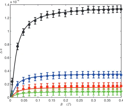
FIG. 1. (Color online) Birefringence (n) as a function of external magnetic field (Bext) at different volume fractions (f) of the nanoparticles. Measurements at the maximum volume fraction are presented by circles; this concentration was diluted by factors of 2 (diamonds), 4 (squares), and 8 (triangles). The best fit to the data was obtained atμ(2)=(1.4±0.1)μ, whereμ=6×10⁴μ
B is the
value of the measured magnetic moment of a single nanoparticle. The wavelength of light is 633 nm.
V. RESULTS AND DISCUSSION
Figure 1 shows the dependence of the measured bire-fringence on the external magnetic field at different volume fractions of nanoparticles. The birefringence due to the cyclohexane is negligible as is the birefringence of spherical nanoparticles, so the observed birefringence is due to the dimers. Theoretical curves are obtained by fitting Eq. (12)
to the data with the magnetic moment [μ(2)] of a dimer and the volume fraction of dimers [f(2)] as fitting parameters. The wavelength of light was 633 nm. The plasma frequency was obtained from the measurements of the Faraday rotation [22], where it was found thatωpτ =190±6 ifτ =2×10⁻¹⁴ s. For cyclohexane εh=2.0 and for dimers L⊥=0.17. The temperature wasT =300 K. The best fit of the experimental data is found atμ(2)=(1.4±0.1)μ, whereμ=6×10⁴μB is the value of the measured magnetic moment of a single nanoparticle with a diameter of 11 nm (without the coating), determined from the analysis of Faraday rotation for the same sample [22]. Our results for the magnetic moment of a dimer confirm the flexible chain theory by Mendelev and Ivanov [33], since the magnetic moment of a dimer should be twice the magnetic moment of a single nanoparticle if internal orientational fluctuations of particles in a chain were negligible. Using the expressions derived by Mendelev and Ivanov we have calculated the zero-field correlation coefficient (K) between the orientations of the two neighboring particle magnetic moments in a chain and find it to be
[image:4.608.315.555.75.283.2]0.1 1 10−8
10−7 10−6
f/f ma x
Δ
n
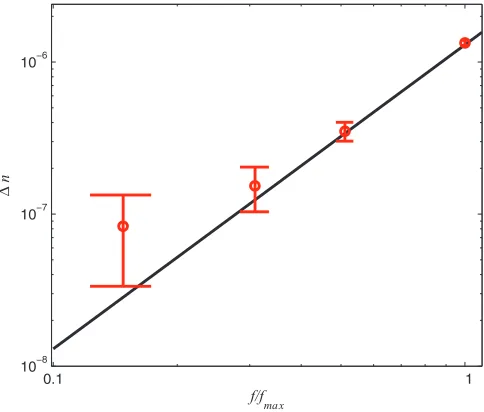
FIG. 2. (Color online) Measured birefringence (n) as a function of the relative volume fraction of nanoparticles (f/fmax), wherefmax is the maximum volume fraction used in the experiments. The black line presents the dependencen∝f2.
however, the results agree qualitatively and confirm that internal fluctuations of particles in a chain cannot be neglected. The volume fraction of dimers has to be fitted at each volume fraction of nanoparticles. At the largest value of f
(black data points in Fig. 1) we find f(2)∼2×10⁻⁸ (at
ωpτ =190). Withf ∼4×10⁻⁴(a value that, unfortunately, is the least accurate one in our measurement and can be twice as large or half as large) one thus expects a few dimers per 104 monomers. Using Eq.(7)andU0=3.4 (for nanoparticles with diameterd =13 nm, including the surfactant coating, and a magnetic moment of 6×10⁴μB) we calculate the theoretical value for the dimer volume fractionf(2)∼8×10⁻⁸at strong fields. We find qualitative agreement of the volume fractions of dimers obtained from the experiment and theory. Considering the crudeness of the model and also the low accuracy in measuring the volume fraction as well as the fact that there is also a distribution of particle diameters, we find the agreement satisfactory.
Figure 2 shows the log-log diagram of the measured birefringence as a function of the volume fraction of nanopar-ticles. The solid line presents the fit of quadratic dependence
n∝f2. There are some discrepancies at lower volume fractions; however, the experimental error is rather large at very low volume fraction due to the procedure used to prepare diluted samples.
VI. CONCLUSIONS
We have studied magnetic-field-induced birefringence in ferrofluids composed of cobalt nanoparticles dispersed in
cyclohexane. The measured birefringence is due to the for-mation of chains of nanoparticles. Since the volume fraction of nanoparticles is very low, only formation of dimers can be expected. The volume fraction of dimers has been obtained from the measurements of birefringence and it has been compared with the theoretical prediction obtained from the density functional approach. The theoretical prediction and the experimental results agree well, particularly given the crudeness of the measurements (due to the particle size distribution and the experimental error in determination of the volume fraction).
The expected magnetic moment of a dimer was obtained from the measurements of the birefringence as a function of the external magnetic field. We find the magnetic moment of a dimer to be 1.4 times the magnetic moment of a monomer. This result shows that internal particle fluctuations inside the chain play an important role, as suggested theoretically in Ref. [33].
The analysis presented in this paper is valid at very low volume densities of inclusions. Since we were studying the optical properties in a 1-cm-thick cuvette, we had to work with very low concentrations:f ∼10−4and less in order to have a measurable optical transmittance. At higher volume fractions of nanoparticles chains of more than two nanoparticles must be considered as well. For example, atf =0.05 the number of dimers is already comparable with the number of monomers and there is a significant number of chains with higher number of particles [34], which, at high magnetic fields, are also expected to form ordered chain phases [41]. In addition to chains, particles can also form clusters and rings. Zubarev et al.[42] showed that if the number of particles interacting is fewer than 5, the concentration of chains is much larger than the concentration of clusters and rings. They study two-dimensional ferrofluids and find significant concentrations of clusters at a volume fraction of nanoparticles equal to 0.14, but at a volume fraction of 0.03, the volume fraction of clusters is already significantly reduced. We were studying samples in which the volume fraction of nanoparticles was from 10−5to 10−4. Since the experimental results agree well with the theory that accounts only for formation of chains, we can conclude that, in such diluted systems, indeed, only two-particle chains need to be considered.
ACKNOWLEDGMENTS
The authors wish to acknowledge the TEAM program from FNP (Project TEAM/2010-5/4, Self-assembly of functional-ized inorganic-organic liquid crystalline hybrids for multi-functional nanomaterials) for financial support. This work was also supported by the Slovenian-Polish joint research project Liquid Crystalline Phases Made by Metal Nanoparticles and the research program P1-0055 financed by the Slovenian Research Agency (ARRS).
[1] S. Odenbach (ed.), Colloidal Magnetic Fluids: Ba-sics, Development and Application of Ferrofluids, Lec-ture Notes in Physics Vol. 763 (Springer, Berlin, 2009);
[image:5.608.52.294.71.277.2][2] R. E. Rosenweig, Ferrohydrodynamics (Dover, New York, 1997).
[3] B. Berkovski and V. Bashtovoy (eds.), Magnetic Fluids and Applications Handbook(Begel House, Wallingford, 1997). [4] E. Blums, A. Cebers, and M. M. Maiorov,Magnetic Fluids(de
Gruyter, Berlin, 1997).
[5] S. F. Medeiros, A. M. Santos, H. Fessi, and A. Elaissari,Int. J. Pharm.403, 139 (2011).
[6] A. M. Schmidt,Colloid Polym. Sci.285, 953 (2007).
[7] Y. Zhao, Y. Zhang, R. Lv, and. Q. Wang,J. Magn. Magn. Mater.
323, 2987 (2011).
[8] H. E. Horng, C. S. Chen, and K. L. Fang,Appl. Phys. Lett.85, 5592 (2004).
[9] S. L. Pu and X. F. Chen,Appl. Phys. Letts.87, 021901 (2005). [10] C. Y. Hong and S. Y. Yang,J. Magn. Magn. Mater.297, 71
(2006).
[11] J. J. Chieh, C. Y. Hong, and S. Y. Yang,J. Nanopart. Res.12, 293 (2010).
[12] H. E. Horng, J. J. Chieh, Y. H. Chao, and S. Y. Yang,Opt. Lett.
30, 543 (2005).
[13] T. Liu, X. F. Chen, and Z. Y. Di,Appl. Phys. Lett.91, 121116 (2007).
[14] Y. Zou, K. Liu, Z. Shen, and X. Chen,Microfluid Nanofluid10, 447 (2011).
[15] S. Neveu-Prin, F. A. Tourinho, J.-C. Bacri, and R. Perzynski, Colloids Surf. A80, 1 (1993).
[16] E. Hasmonay, E. Dubois, J.-C. Bacri, R. Perzynski, Yu. L. Raikher, and V. I. Stepanov,Eur. Phys. J. B5, 859 (1998). [17] E. Hasmonay, J. Depeyrot, M. H. Sousa, F. A. Tourinho, J.-C.
Bacri, R. Perzynski, Yu. L. Raikher, and I. Rosenman,J. Appl. Phys.88, 6628 (2000).
[18] E. Hasmonay, J. Depeyrot, M. H. Sousa, F. A. Tourinho, J.-C. Bacri, and R. Perzynski,J. Magn. Magn. Mater.201, 195 (1999). [19] E. S. Kooij, A. C. Galca, and B. Poelsema,J. Colloid Interface
Sci.304, 261 (2006).
[20] K. Skeff Neto, A. F. Bakuzis, P. C. Morais, A. R. Pereira, R. B. Azevedo, L. M. Lacava, and Z. G. M. Lacava,J. Appl. Phys.89, 3362 (2001).
[21] J. P. Llewellyn,J. Phys. D16, 95 (1983).
[22] J. Szczytko, N. Vaupotiˇc, K. Madrak, P. Sznajder, and E. Gorecka,Phys. Rev. E87, 033201 (2013).
[23] P. G. de Gennes and P. A. Pincus, Phys. Kondens. Mater.11, 189 (1970).
[24] K. Butter, P. H. H. Bomans, P. M. Frederik, G. J. Vroege, and A. P. Philipse,Nat. Mater.2, 88 (2003).
[25] M. Klokkenburg, C. Vonk, E. M. Claesson, J. D. Meeldijk, B. H. Ern´e, and A. P. Philipse,J. Am. Chem. Soc.126, 16706 (2004).
[26] M. Klokkenburg, B. H. Ern´e, A. Wiedenmann, A. V. Petukhov, and A. P. Philipse, Phys. Rev. E 75, 051408 (2007).
[27] S. Taketomi,Jpn. J. Appl. Phys.22, 1137 (1983).
[28] N. A. Yusuf, I. Qasmieh, and H. Abu-Safia,J. Magn. Magn. Mater.166, 374 (1997).
[29] Z. Di, X. Chen, S. Pu, X. Hu, and Y. Xia,Appl. Phys. Lett.89, 211106 (2006).
[30] Q. Zhang J. Wang, and H. Zhu,J. Appl. Phys.78, 3999 (1995). [31] B. R. Jennings, M. Xu, and P. J. Ridler,J. Phys. D34, 1617
(2001).
[32] M. A. Osipov, P. I. C. Teixeira, and M. M. Telo da Gama,Phys. Rev. E54, 2597 (1996).
[33] V. S. Mendelev and A. O. Ivanov, Phys. Rev. E70, 051502 (2004).
[34] A. O. Ivanov and S. S. Kantorovich,Phys. Rev. E70, 021401 (2004).
[35] J. J. Weis and D. Levesque, Phys. Rev. Lett. 71, 2729 (1993).
[36] P. M. Hui and D. Stroud,Appl. Phys. Lett.50, 950 (1987). [37] D. Stroud,J. Appl. Phys.66, 2585 (1989).
[38] T. K. Xia, P. M. Hui, and D. Stroud,J. Appl. Phys.67, 2736 (1990).
[39] M. Rasa,J. Magn. Magn. Mater.201, 170 (1999). [40] M. Rasa,Eur. Phys. J. E2, 265 (2000).
[41] J.-J. Weis,J. Phys.: Condens. Matter15, S1471 (2003). [42] A. Y. Zubarev and L. Y. Iskakova,Phys. Rev. E 76, 061405