1
Static
Highly Elliptical
Orbits using Hybrid Low-
Thrust
Propulsion
Pamela Anderson 1 and Malcolm Macdonald2 University of Strathclyde, Glasgow, G1 1XJ, Scotland, E.U.
Static highly-elliptical orbits enabled using hybrid solar-sail/solar-electric propulsion are
investigated. These newly proposed orbits, termed Taranis orbits, have free selection of
‘critical inclination’ and use low-thrust propulsion to compensate for the drift in argument
of perigee caused by Earth’s gravitational field. In this paper, a 12-hr Taranis orbit with an
inclination of 90deg is developed to illustrate the principle. The acceleration required to
enable this novel orbit is made up partly by the acceleration produced by solar-sails of
various characteristic accelerations, and the remainder supplied by the electric thruster.
Order of magnitude mission lifetimes are determined, a strawman mass budget is also
developed for two system constraints, firstly spacecraft launch-mass is fixed, and secondly
the maximum thrust of the thruster is constrained. Fixing maximum thrust increases
mission lifetimes, and solar-sails are considered near to mid-term technologies. However,
fixing mass results in negligible increases in mission lifetimes for all hybrid cases considered,
solar sails also require significant development. This distinction highlights an important
contribution to the field, illustrating that addition of a solar-sail to an electric propulsion
craft can have negligible benefit when mass is the primary system constraint. Technology
requirements are also outlined, including sizing of arrays, propellant tanks and
solar-sails.
1
PhD Candidate, Advanced Space Concepts Laboratory, [email protected]
2
Nomenclature
a = Semi-major axis, km
ap = Solar Electric Propulsion acceleration, mm/s2
as = Solar Sail Acceleration, mm/s2
As = Solar sail area, m2
asc = Solar sail characteristic acceleration, mm/s2
atot = Total solar sail and Solar Electric Propulsion acceleration, mm/s2
e = Eccentricity
Fr = Low-thrust radial perturbation scalar
Ft = Low-thrust transverse perturbation scalar
G = Universal gravitational constant, m3/kg s-2
g0 = Gravity of the Earth, m/s2
i = Inclination, degrees
Isp = Specific impulse, sec
J2 = Perturbation due to Earth oblateness
ksa = Solar array specific performance, kg/W
kSEP = Solar Electric Propulsion specific performance, kg/W
L = Mission lifetime, years
m = Spacecraft mass, kg
m0 = Initial mass, kg
mf = Final mass, kg
mp = Power system mass, kg
mpay = Payload mass, kg
mprop = Propellant mass, kg
ms = Solar sail mass, kg
msc = Mass of spacecraft excluding solar sail, kg
mSEP = Solar Electric Propulsion thruster mass, kg
3
mtank = Propellant tank mass, kg
n = Solar sail thrust vector
p = Semi-parameter, km
Pmax = Maximum power, kW
r = Orbital radius, km
ȓ = Sun-sail vector
Re = Mean radius of Earth, km
tf = Final time, sec
Tmax = Maximum thrust, N
Δt = Mission duration, sec
α = Locally optimal sail pitch angle, degrees
= Pitch angle for ideal force vector, degrees
β = Solar sail lightness number
δ = Locally optimal sail clock angle, degrees
η = Solar sail efficiency
ηSEP = Solar Electric Propulsion efficiency
ϑ = Angle measured from the first point of Aries to the planet, within the ecliptic plane
θ = True anomaly, degrees
λω = Rate of change of argument of perigee
µ = Gravitational parameter of Earth, km3/s2
σs = Solar sail loading parameter, g/m2
σ* = Critical solar sail loading parameter, g/m2
ω = Argument of perigee, degrees
Ω = Ascending node angle, degrees
I.
Introduction
HE extension of highly elliptical orbits (HEOs) using low-thrust propulsion to counteract the perturbations due
to the Earth’s gravity have previously been considered, to enable HEOs with free selection of the ‘critical
α
4
inclination’ [1], with no rotation of the apsidal line [2-4]. Such orbit extensions are termed Taranis orbits [4]. One
particular example is the 12-hr Taranis orbit inclined at 90deg to the equator to enable continuous observation of
frigid and neighboring temperate regions. Previously, Taranis orbits have been considered using Solar Electric
Propulsion (SEP), a mature technology with a high Technology Readiness Level (TRL) [5, 6] and low Advanced
Degree of Difficulty (AD2) [5, 6]. However, mission lifetimes are limited by the amount of propellant that can be
carried. Consequently, consideration is given to the addition of a solar sail to the system. Solar sails exploit solar
radiation pressure generated by photons reflecting off a large, highly reflective sail to produce a continuous,
propellant–less thrust. Hybrid SEP / solar sail systems reduce the propellant requirements of the SEP thruster, while
the SEP system compensates for the inability of the solar sail to thrust in the direction of the Sun. The use of a small
solar sail on the spacecraft also contributes towards lowering the AD2 of solar sailing [5]. It is also noted that the
addition of a solar sail to the system will create system level design complexities, however these effects are
considered out with the scope of the paper, and are consequently neglected to allow a simple comparison to be
made.
The complementary nature of the two propulsion systems enables a new range of missions in which continuous
low-thrust is required. These hybrid solar sail / SEP systems have been proposed for various applications including
geostationary orbits (GEO) displaced above or below the equatorial plane to create new geostationary slots [7].
Moreover, the hybrid propulsion concept has recently been proposed to modify the well-known Pole Sitter mission
concept [8], enabling a spacecraft to be statically stationed high above one of the Earth’s poles at over two-million
kilometers range, giving continuous observation of the Earth’s poles using a single spacecraft [9-11]. In each of
these studies considering hybrid solar sail / SEP propulsion, either the launch mass of the spacecraft has been fixed
or the maximum thrust from the SEP system has constrained the analysis. However, in this paper the comparison is
made between the two constraining parameters to determine the most beneficial scenario and the development in
solar sailing technology required.
This paper significantly extends the work introduced in [2-4] by considering the addition of a solar sail to the
SEP system, to enable the Taranis orbits using a hybrid SEP / solar sail low-thrust propulsion system. Two cases are
considered assuming different constraining parameters. Firstly, it is assumed that the launch mass of the spacecraft
is fixed. Thus the mass of the solar sail added to the system is limited to be no more mass than the amount of
5
thrust of the SEP system, thus allowing the initial mass of the spacecraft to vary. Consideration is given to allocating
this additional mass in two ways, in the first instance; it is assigned solely to the solar sail. In the second instance it
is used in part for the solar sail and in part to increase the useful payload capacity. The impact of the added solar sail
is considered on mission lifetime along with the development of strawman mass budgets to quantify the benefit of a
hybrid SEP / solar sail system over a pure SEP system.
II.
Taranis Orbits
Taranis orbits are HEOs unconstrained by orbit period, perigee and apogee altitude or inclination. They are
characterized by the application of a small continuous acceleration to ensure no rotation of the apsidal line due to the
oblateness of the Earth. The total acceleration required to achieve a Taranis orbit of any inclination is obtained from
the expression for the change in argument of perigee, due to J2 effects and the addition of continuous radial and
transverse acceleration only [2]. It is noted that the out of plane acceleration is not included in this term, as it has
been shown previously in [4] that the normal acceleration component offers limited value and significantly
complicates both the analytical expressions and the spacecraft control profile.
(
)
(
)
2(
)
(
)
20 J Fr Ft
π
ω
ω
ω
ω
Δ = Δ + Δ + Δ (1)
where each acceleration component is given by
(
)
(
( )
)
(
)
2 2 2 2 23 3 5 2 4 1
e J
J R cos i
a e
π
ω
+ Δ = − + (2) Δω( )
Fr = 1eµ2a
2F
r(−2+2e 2
−4e −1+e2Arctanh −1+e
−1+e2
! " # # $ % & &
−e −1+e2ln 1−e
−1+e2 ! " # # $ % &
&+e −1+e
2ln −1+e
−1+e2
! " # # $ % & &) (3)
(
)
(
)
2 2 4 2 t t Fa e F
e
ω
µ
− +
6
The orbital elements from Table 1 are substituted into Eq. (1), for an inclination of 90deg, and the change in
argument of perigee is set equal to zero results in the expression for the radial acceleration as a function of
transverse acceleration. It is noted that for the orbits considered in the paper i.e. e < 1, Eq. (3) contains complex
numbers in the arguments, however when the orbital parameters from Table 1 are substituted into the equation, the
acceleration required to change the argument of perigee is real.
4 1.579 1.676
r t
F e− F
=− + (5)
The transverse acceleration is assigned a range of values between 0mm/s2 and 0.1mm/s2 and the corresponding radial
acceleration is found using Eq.(5). From this, it is found that the minimum acceleration magnitude occurs when the
transverse acceleration is equal to 0.07mm/s2 and the corresponding radial acceleration is -0.0406mm/s2,this results
in a total required acceleration magnitude of 0.0809 mm/s2.
Table 1 Orbital parameters.
Orbital Element Value
Perigee Altitude 813 (km)
Apogee Altitude 39540 (km)
Ascending Node 330 (deg)
Argument of perigee 270 (deg) unless otherwise stated
III.
Hybrid SEP / Solar Sail Propulsion
To lower the demands placed upon the SEP system, by lowering its required thrust, the use of hybrid SEP / solar
sail propulsion to maintain the Taranis orbit is considered. The total acceleration needed to maintain the Taranis
orbit has been shown as 0.0809mm/s2; using hybrid propulsion a fraction of this acceleration is now generated by
the solar sail with the SEP system supplying the remainder of the acceleration. The total required acceleration is
given by
tot s p
a =a +a (6)
where as is the acceleration generated by a perfectly reflecting solar sail [12]
as=βGms
r2 (ˆr dot n)
7
and where β is the dimensionless sail lightness number given as*
s
σ
β
σ
= (8)
The critical sail loading, σ*, in Eq. (8), is equal to 1.53g/m2 [12], and the sail loading, σs, is the ratio of the spacecraft
mass to solar sail area
s s
s
m A
σ
= (9)A parallel design parameter to the sail loading is the solar sail characteristic acceleration, and is defined as the
actual acceleration experienced by the sail at a solar distance of 1 AU with the sail surface normal to the Sun, and
may be written as [12]
2 sc
s
P
a
η
σ
= (10)
At a distance of 1AU from the Sun the magnitude of the solar radiation pressure, P, exerted on a perfectly
absorbing surface is 4.56 x 10⁻⁶ N/m2[12]. The solar sail efficiency,η, is a function of the optical properties of the
sail film and the sail shape, and accounts for the finite reflectivity of the film; typically this taken to be of the order
of 0.85-0.9 [12].
2 ( / )
sc
s sc s
P a
m A
η
σ
=+ (11)
Equation (11) shows that the sail characteristic acceleration is a function of the spacecraft mass, msc, excluding the
solar sail mass The mass of the spacecraft will decrease as the SEP thruster consumes propellant. Thus, the sail
characteristic acceleration increases over time.
Locally Optimal Control Laws
Locally optimal control laws are used to maximize the instantaneous rate of change of a given orbital element
and provide the required thrust orientation in analytical form [13]. Where, locally optimal refers to optimal at a
8
SEP system uses the simple switching law previously derived [4]. In the absence of any low-thrust propulsion to
maintain the 12hr Taranis orbit, the natural drift in argument of perigee due to the gravitational perturbation is
-0.15deg per day (towards the ascending node). Thus, it is required that the sail attempt to impart positive rate of
change of argument of perigee to compensate for this drift. The argument of perigee locally optimal control law is
derived from the argument of perigee variational equation, given in terms of classical orbital elements
dω
dθ = R T N
! "#
$
%&λω (12)
where
(
)
1 cot p cos e p r sin p e r isin p ω θ λ θ θ ω ⎡ ⎤ − ⎢ ⎥ ⎢ ⎥ ⎢ ⎛ ⎞ ⎥ ⎢ ⎥ = ⎜ + ⎟ ⎢ ⎝ ⎠ ⎥ ⎢ ⎥ ⎢− + ⎥ ⎢ ⎥ ⎣ ⎦ (13)The locally optimal control law thus requires the solar sail thrust to be maximized along λω, [13]. The solar
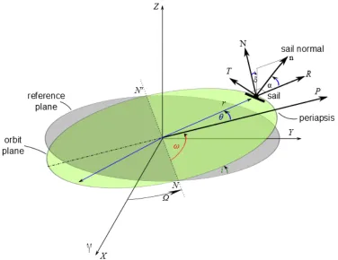
[image:8.612.72.208.203.375.2]sail trajectory is planet-centered; therefore λωmust be transposed into the Sun-sail line reference frame, shown in
Fig. 1, using standard transformation matrices. The transformation is performed in two stages; first, transformation
from planet-centered RTN to Earth-centered inertial using the inverse of the transformation matrix [14]
(
)
(
)
(
)
(
)
(
)
(
)
(
)
(
)
(
)
(
)
cos cos cos cos sin sin RTN ECI ECIO T O
cos cos sin isin cos sin sin icos sin sini sin cos cos isin sin sin cos icos cos sini O
isin icos cosi
ω θ ω θ ω θ ω θ ω θ
ω θ ω θ ω θ ω θ ω θ
=⎡ ⎤⎣ ⎦
⎡ + Ω − + Ω + Ω+ + Ω + ⎤
⎢ ⎥
=⎢− + Ω − + Ω − + Ω+ + Ω + ⎥
⎢ Ω − Ω ⎥
⎣ ⎦
9
Fig. 1 Orientation of solar sail pitch and clock angles.
The second stage is to transform from Earth-centered inertial to Sun-line coordinates, using the transformation
matrix given in Eq.(15) [14]. It is noted that orthogonal coordinate systems are employed and that parallax effects
are negligible.
[ ]
0
SUN ECI ECI
cos sin cos sin sin
O T O sin cos cos cos sin O
sin cos
ϑ ϑ ε ϑ ε
ϑ ϑ ε ϑ ε
ε ε
⎡ ⎤
⎢ ⎥
= =⎢− ⎥
⎢ − ⎥
⎣ ⎦
(15)
With conversion of λω into the Sun-sail line coordinate system, the pitch angle of the ideal force vector is found
using Fig. 1, and is given as
α=arccos λxˆ ss
( )
(16)where,λˆ ss / λ ss / λ ssz / λ ˆss ˆss ˆss
x y ω x y z
ω =⎡⎣
λ
ω ωλ
ω ωλ
ω⎦⎤=⎣⎡λ
ωλ
ωλ
ω ⎤⎦, the unit argument of perigee vector taken from theco-10
ordinate system and subscripts x, y, and z refer to the x, y, and z components of the argument of perigee vector. The
sail orientation to maximize the sail thrust vector is found, the locally optimal sail pitch angle is given from [15]
tanα=−
3cosα+ 9cos2
( )
α +8sin2( )
α4sinα (17)
The locally optimal sail clock angle is also found using Fig. 1 and is given as
ˆ ˆ 2 2 ˆ
arccos
z
z y
λ
δ
λ
λ
⎛ ⎞
⎜ ⎟
=
⎜ + ⎟
⎝ ⎠
(18)
The solar sail thrust vector in Eq. (7) is found using [12]
cos sin sin sin cos
n
α α δ α δ
⎡ ⎤
⎢ ⎥
=⎢ ⎥
⎢ ⎥
⎣ ⎦
(19)
Where α is the sail pitch angle, or the angle between the sail normal and incident radiation, and δ is the sail clock
angle, the angle measured within a plane normal to the Sun line from the projection of the orbit normal vector in that
plane. As the sail is in an Earth-centered trajectory the normal vector orientation given in Eq. (19) must be
transformed into planet-centered RTN coordinates. This is again performed in two stages transforming from
Sun-line coordinates to Earth-centered inertial, using the inverse of the transformation matrix given in Eq. (15), and from
Earth-centered inertial to Earth-centered RTN, using the matrix in Eq. (14).
General perturbations methods are used to determine the total acceleration required to enable the Taranis orbits.
Special perturbations methods use these acceleration values and numerically integrate the Lagrange planetary
equations including the motion of the solar sail. Using the defined solar sail equations, various solar sail
characteristic accelerations are considered to determine the sail characteristic acceleration that offers the most
benefit in terms of the lowest acceleration demand on the SEP system. As the characteristic acceleration of the sail is
increased, at some point the acceleration provided by the solar sail will be so high that the SEP system will be
required to counteract the sail acceleration, rather than supplement it. Using a spacecraft with an initial mass of
11
mass of the spacecraft is shown in Fig. 2 over the first year of operation, the remaining mass is also shown in Fig. 3
[image:11.612.128.492.120.455.2]as a function of the solar sail characteristic acceleration over various time intervals.
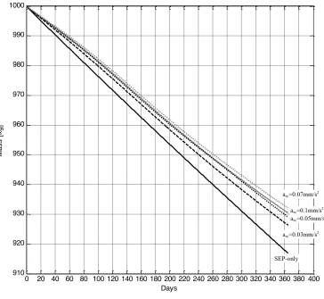
Fig. 2 Fuel consumption of spacecraft over one year using various solar sail characteristic accelerations.
0 20 40 60 80 100 120 140 160 180 200 220 240 260 280 300 320 340 360 380 400
910 920 930 940 950 960 970 980 990 1000
Days
Ma
s
s
[
k
g
]
SEP only asc=0.03mm/s2
asc=0.05mm/s2
asc=0.07mm/s2
asc=0.1mm/s2
12
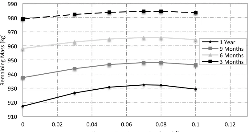
Fig. 3 Remaining mass as a function of characteristic acceleration.
It is seen from Fig. 2 that, as expected, each solar sail considered offers some benefit over the SEP-only case, by
decreasing the amount of propellant consumed, thus increasing the final spacecraft mass. The solar sail with a
characteristic acceleration of 0.07mm/s2 offers the highest reduction in fuel consumption. This turning point was
determined by a process of trial and error, increasing the characteristic acceleration in increments of 0.001 mm/s2.
Increasing the characteristic acceleration above this value causes the SEP system to counteract the acceleration
generated by the solar sail, thus increasing the fuel consumption of the SEP system. This turning point will,
however, move as the SEP system uses up propellant and the solar sail acceleration increases, as in Eq (11). The
maximum propellant mass saving over the first year, given by a sail characteristic acceleration of 0.07mm/s2, is just
over 15kg. With characteristic accelerations of 0.03mm/s2 and 0.05mm/s2 offering reductions in propellant
consumption of around 9kg and 13.5kg respectively.
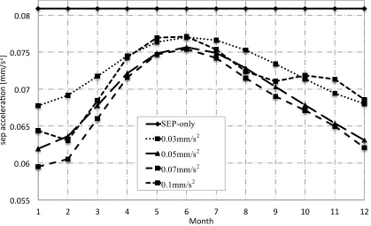
The acceleration provided by the solar sail varies throughout the year due to the tilt of the Earth’s rotational axis
with respect to the orbit plane, thus the acceleration required by the SEP system varies throughout the year, the
necessary SEP acceleration is shown in Fig. 4.
910 920 930 940 950 960 970 980 990
0 0.02 0.04 0.06 0.08 0.1 0.12
Re
m
ai
ni
ng
Mas
s
[k
g]
Characteris>c Accelera>on [mm/s2]
13
Fig. 4 SEP acceleration required over one year.
Fig. 4 shows that from April to August the acceleration from the sail decreases, thus the maximum demand on
the SEP system occurs during this time. A significant decrease in the required SEP acceleration is shown throughout
the Northern Hemisphere winter. The turning point described in Fig. 2 is again explained in Fig. 4, where it is shown
that the acceleration generated by the solar sail with a characteristic acceleration of 0.1mm/s2 is so high that the SEP
thruster has to counteract this.
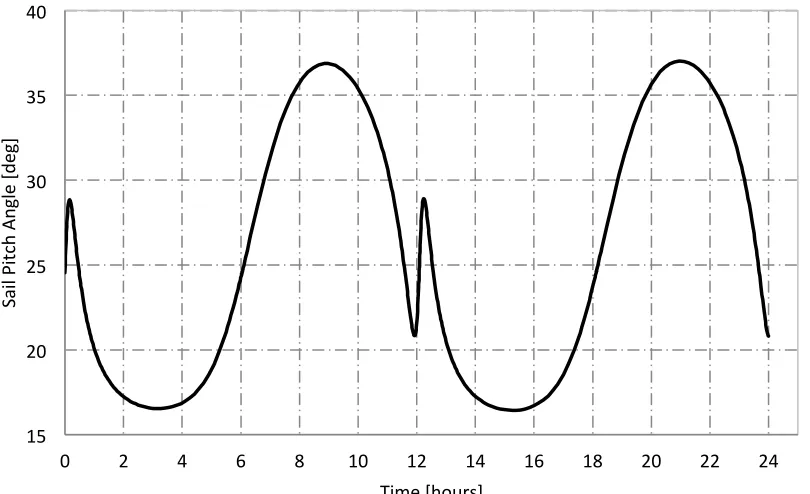
The solar sail control angles required to achieve the 90deg inclination Taranis orbits and accomplish the stated
reduction in total SEP accelerations are shown in Fig. 5 and Fig. 6.
0.055 0.06 0.065 0.07 0.075 0.08
1 2 3 4 5 6 7 8 9 10 11 12
se
p
ac
ce
le
ra>
on
[m
m
/s
2]
Month SEP only 0.03mm/s^2 0.05mm/s^2 0.07mm/s^2 0.1mm/s^2 SEP-only
0.03mm/s2
0.05mm/s2
0.07mm/s2
14
Fig. 5 Solar Sail Pitch Angle.
Fig. 6 Solar Sail Clock Angle.
From Fig. 5 it is shown that the sail pitch angle must rotate by around 20deg per orbit, while from Fig. 6 the sail
clock angle has been plotted from -180deg to 180deg to show the motion is smooth, the sail clock angle therefore
15 20 25 30 35 40
0 2 4 6 8 10 12 14 16 18 20 22 24
Sai
l P
itc
h
An
gl
e
[d
eg
]
Time [hours]
320 330 340 350 360 370 380 390 400
0 2 4 6 8 10 12 14 16 18 20 22 24
Sai
l C
lo
ck
A
ng
le
[d
eg
]
[image:14.612.106.509.86.624.2]15
completes three 360deg revolutions within 12-hrs. The relatively short orbit period of the Taranis orbits, means that
fast slew maneuvers are required by the solar sail, which are currently beyond the current capabilities of solar sail
technology.
IV.
Mission Analysis
Mission Lifetime
By evaluating the performance of the 12-hr Taranis orbit in terms of propellant consumption, possible mission
lifetimes of the orbit facilitated by means of SEP-only and hybrid SEP/solar sail systems are determined. In the
hybrid SEP/solar sail systems the constant acceleration is given by taking the average acceleration required by the
SEP system over the first year, given in Table 2.
0
0
ln f sp
f
p
m I g L t
m a
⎛ ⎞ = =− ⎜ ⎟ ⎝ ⎠
(20)
where, the mass fraction mf/m0 is defined as
(
0)
0 0
prop
f m m
m
m m
−
[image:15.612.158.455.483.571.2]= (21)
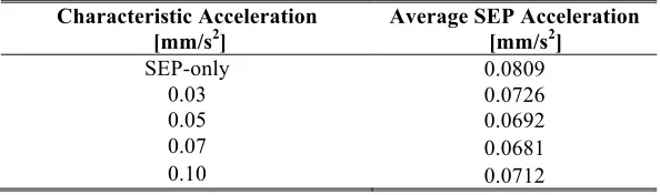
Table 2 Average SEP Acceleration over a 12 month period.
Characteristic Acceleration Average SEP Acceleration
[mm/s2] [mm/s2]
SEP-only 0.0809
0.03 0.0726
0.05 0.0692
0.07 0.0681
0.10 0.0712
It is noted from Table 2 that the acceleration required from the SEP system decreases by less than the sail
characteristic acceleration, this is due to the useful sail acceleration magnitude being set by the square of the cosine
of the pitch angle. The lifetime of the 90deg, 12-hr Taranis orbit, detailed in Table 1, is thus determinable for a
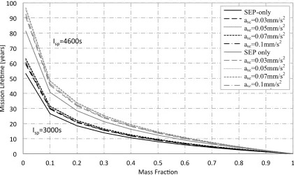
particular mass fraction and specific impulse. The resulting possible mission lifetimes are shown in Fig. 7 for the
16
Fig. 7 Taranis mission lifetime as a function of mass fraction for SEP-only and various solar sail
characteristic accelerations.
Fig. 7 shows the possible mission lifetimes for the Taranis orbit as a function of mass fraction for specific
impulses of 3000s and 4600s, using SEP / sail systems with various solar sail characteristic accelerations. For
example, using a mass fraction of 0.5 the resulting mission lifetime for each system and both specific impulses is
given in Table 3.
Table 3 Mission lifetime.
Isp=3000s Isp=4600s
Characteristic Acceleration [mm/s2] Lifetime [years] Lifetime [years]
SEP-Only 8.0 12.3
0.03 9.0 13.7
0.05 9.3 14.3
0.07 9.5 14.6
0.10 9.1 13.9
Table 3 shows that employing a solar sail with a characteristic acceleration of 0.07mm/s2 can enable a mission
around a year and a half longer than a Taranis orbit enabled using a pure SEP system, with a specific impulse of
3000s. It is also shown that an increase in lifetime of over two years is possible increasing the specific impulse to
4600s. This highlights the benefit of the hybrid solar sail / SEP system due to the reduced propellant consumption
0 10 20 30 40 50 60 70 80 90 100
0 0.1 0.2 0.3 0.4 0.5 0.6 0.7 0.8 0.9 1
Mi
ss
io
n
Li
fe
>m
e
[y
ear
s]
Mass Frac>on
SEP
a=0.03mm/s^2 a=0.05mm/s^2 a=0.07mm/s^2 a=0.1mm/s^2 SEP
a=0.03mm/s^2 a=0.05mm/s^2 a=0.07mm/s^2 a=0.1mm/s^2
I
sp=4600s
I
sp=3000s
SEP-only
asc=0.03mm/s2
asc=0.05mm/s2
asc=0.07mm/s2
asc=0.1mm/s2
SEP only
asc=0.03mm/s2
asc=0.05mm/s2
asc=0.07mm/s2
17
from the SEP-only system. It is noted that this is a conservative analysis, as the sail will become more effective as
the SEP propellant is depleted and hence the mission lifetimes will in fact be longer than detailed here.
Initial Spacecraft Mass
The maximum allowable initial mass of the spacecraft is determined for the given level of thrust, using the
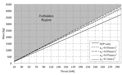
constant SEP accelerations given in Table 2;the maximum allowable mass is shown in Fig. 8, determined using the
following expression
max 0 p
[image:17.612.85.511.272.536.2]T =m a (22)
Fig. 8 Maximum allowable initial mass for the 12-hr Taranis orbit in Table 1.
Fig. 8 shows the valid region for the initial mass of the spacecraft, where the forbidden region is the area where
the thrust / mass ratio is less than that required to maintain the orbit. Two separate factors can constrain the system;
firstly, where the launch mass of the spacecraft is fixed and secondly where the maximum thrust of the SEP system
is used to constrain the mission. This paper considers both cases to examine the possible benefits of each.
0 500 1000 1500 2000 2500 3000 3500 4000 4500
10 30 50 70 90 110 130 150 170 190 210 230 250 270 290
Mas
s
[k
g]
Thrust [mN]
SEP
a=0.03mm/s^2 a=0.05mm/s^2 a=0.07mm/s^2 a=0.1mm/s^2
Forbidden
Region
SEP-only
asc=0.03mm/s2
asc=0.05mm/s2
asc=0.07mm/s2
18
Fixed Launch Mass
Firstly, the case where the launch mass of the spacecraft is fixed is considered. Selecting three initial masses of
[image:18.612.73.538.164.251.2]spacecraft of 1000kg, 1500kg and 2500kg the corresponding required initial thrust values are given in Table 4.
Table 4 Maximum initial thrust values.
1000kg 1500kg 2500kg
Characteristic Acceleration [mm/s2] Initial Thrust [mN] Initial Thrust [mN] Initial Thrust [mN]
SEP-Only 80.9 121.4 202.3
0.03 72.6 108.9 181.5
0.05 69.2 103.8 173.0
0.07 68.1 102.2 170.3
0.10 71.2 106.8 178.0
Table 4 shows that for a particular initial mass of spacecraft, the addition of a solar sail, reduces the thrust
required by the SEP thruster. With the maximum reduction in thrust of 32mN, occurring for the 2500kg spacecraft
with a solar sail with a characteristic acceleration of 0.07mm/s2 characteristic acceleration solar sail. Note that the
additional mass incurred by adding a solar sail remains constrained by the fixed launch mass. As such, the solar sail
mass is constrained to be no more than the saving in propellant mass for a given mission lifetime.
Fixed Maximum Thrust
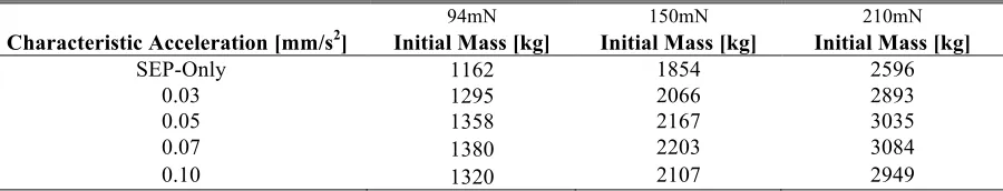
The second case considers the maximum thrust of the SEP system as the constraining parameter. The maximum
allowable initial mass of the spacecraft for a particular thrust value is found using Fig. 8, with the allowable mass
shown to increase for each of the hybrid systems considered. For example, fixing the available SEP thrust at three
particular values of 94mN, 150mN, and 210mN corresponding to the thrust available from NASA’s Solar Electric
Propulsion Technology Application Readiness (NSTAR) thruster [16], the qualified thrust of the QinietiQ T6
thruster, and the maximum thrust of the QinetiQ T6 thruster [17] respectively, results in the maximum allowable
[image:18.612.82.532.576.662.2]mass values given in Table 5.
Table 5 Maximum allowable mass values.
94mN 150mN 210mN
Characteristic Acceleration [mm/s2] Initial Mass [kg] Initial Mass [kg] Initial Mass [kg]
SEP-Only 1162 1854 2596
0.03 1295 2066 2893
0.05 1358 2167 3035
0.07 1380 2203 3084
0.10 1320 2107 2949
Table 5 shows that the addition of solar sails can offer a significant increase in the allowable mass of the
19
mass of around 218kg, 349kg and 488kg for each available thrust. In the first instance this additional mass is
considered to be the total mass of the solar sail added to the system. It is noted that this case will produce no
increase in mission lifetime over the SEP-only case, as there is no additional propellant on board. However, the
relevance of including this case is that it provides the base line solar sail technology. To produce any addition in
mission lifetime, solar sail performance will have to be improved beyond this. In the second instance, the additional
mass is used to add an advanced light-weight solar sail to the system, providing the same characteristic acceleration
and to allow additional SEP propellant useful payload to be carried.
Mass Budget
Although the mission lifetime analysis characterizes possible mission lifetimes of the Taranis mission in terms of
propellant consumption, it should also be investigated whether these conditions allow a useful payload to be carried
using a realistic solar sail. The initial mass of the spacecraft is composed of many elements [9]
0 sys prop tank SEP P pay s
m =m +m +m +m +m +m +m (23)
From Eq.(23), the total mass of the onboard systems, msys, including data processing, telecommunications,
guidance, navigation and control, structural mass, and any power system requirements beyond the SEP system
requirements are assumed to total 500kg. The mass of the SEP thruster, mSEP, is found as a function of the maximum
power provided by the system, Pmax, and is given by
SEP SEP max
m
=
k P
(24)With the specific performance of the thruster given as kSEP = 0.02 kg/W[18] , and the maximum power
max 0 max 2 SP
SEP T I g P
η
= (25)
The thruster efficiency, ηSEP,is assumed to be equal to 0.7. In Eq.(23), mp is the mass of the spacecraft power system
required to provide electrical energy to the SEP system. Thus, using a solar array the mass is given by
P SA max
20
Using a conservative estimate of the specific performance of the solar array, from [19], of kSA = 1/45 kg/W. The
mass of the propellant, mprop, is found as a function of the mission duration, and is given by
max
0 prop
SP
T
m
t
I g
=
Δ
(27)The mass of the propellant tanks, mtank, is a function of the mass of the propellant, mtank=0.1 mprop. Inserting the
appropriate values into Eq. (23) to find the mass of the sub-systems, the remaining mass is the useful payload mass,
mpay, for a range of mission lifetimes. This process is again conducted for both the fixed launch mass and fixed
maximum thrust cases.
Fixed Launch Mass
The maximum solar sail masses that can be added to the spacecraft, for the fixed launch mass case, are
determined from the amount of propellant saved through the use of a hybrid low-thrust propulsion system (Fig. 2).
[image:20.612.179.433.421.489.2]The propellant mass saving per year in orbit for the three given solar sail characteristic accelerations are given in
Table 6.
Table 6 Propellant mass saving per year.
Characteristic Acceleration [mm/s2] Mass Saving [kg]
0.03 9.44
0.05 13.56
0.07 15.25
0.10 12.22
The maximum mass of the solar sail is thus given by the propellant mass saving per year multiplied by the
lifetime of the mission. In this instance, the mission lifetimes used to size the solar sails are given by the SEP-only
case. Where, mission lifetimes are 4.49 years, 6.24 years, and 7.63 years for the 1000kg, 1500kg, and 2500kg
21
Fig. 9 Payload mass as a function of mission lifetime. Fixed launch mass.
Fig. 9 allows the maximum mission lifetime to be determined, that is, where there is no longer any capacity for
useful payload. The maximum mission lifetimes for each initial spacecraft mass, for each of the solar sail
[image:21.612.139.477.458.552.2]characteristic accelerations considered are given in Table 7.
Table 7 Maximum mission lifetimes - fixed launch mass.
Characteristic Acceleration [mm/s2] 1000kg 1500kg 2500kg
SEP-only 4.5 6.2 7.6
0.03 4.6 6.6 8.3
0.05 4.6 6.7 8.5
0.07 4.6 6.8 8.6
0.10 4.5 6.6 8.3
Table 7 shows a modest increase in the Taranis mission lifetime with the addition of a solar sail to the
system, with the maximum increase in lifetime of oneyear, occurring for the 2500kg spacecraft with a solar sail
characteristic acceleration of 0.07mm/s2. Table 7 shows that for the 1000kg and 1500kg spacecraft the increases
in mission lifetime produced by the addition of the solar sail are negligible, with all increases less than half a
year for all solar sails. Thus, it is shown from Table 7 and Eq. (9) - (10), that in order to make any significant
increase in the lifetime of the Taranis mission, a large light solar sail is required, thus, it is expected that
considerable development in solar sail technology is required.
0 200 400 600 800 1000 1200 1400 1600
1 2 3 4 5 6 7 8 9
Pay
lo
ad
Mas
s
[k
g]
Mission Life>me [years]
SEP
a=0.03mm/s^2 a=0.05mm/s^2 a=0.07mm/s^2 a=0.1mm/s^2 SEP
a=0.03mm/s^2 a=0.05mm/s^2 a=0.07mm/s^2 a=0.1mm/s^2 SEP
a=0.03mm/s^2 a=0.05mm/s^2 a=0.07mm/s^2 a=0.1mm/s^2
2500kg
1500kg
1000kg
SEP-only
asc=0.03mm/s2
asc=0.05mm/s2
asc=0.07mm/s2
asc=0.1mm/s2
SEP-only
asc=0.03mm/s2
asc=0.05mm/s2
asc=0.07mm/s2
asc=0.1mm/s2
SEP-only
asc=0.03mm/s2
asc=0.05mm/s2
asc=0.07mm/s2
22
Fixed Maximum Thrust
As constraining the mass of the spacecraft allows very little increase in the lifetime of the Taranis missions
without significant development of the solar sails, the scenario where the maximum thrust of the SEP system is the
constraining parameter is now considered.
Case 1
As previously discussed, in this instance, the mass of each of the solar sails is assumed to equal the additional
mass for the given thrust value (from Fig. 8). The payload mass as a function of mission lifetime is given in Fig. 10
for each of the thrust values considered. In this case the mission lifetime for each initial thrust is the same as the
SEP- only lifetime regardless of the sail characteristic acceleration as all additional mass is used to add the sail and
[image:22.612.100.519.300.541.2]not to add any additional propellant.
Fig. 10 Payload mass as a function of mission lifetime, case 1.
Fig. 10 shows maximum mission lifetimes of around 5.2 years, 6.9 years, and 7.7 years respectively for each of
the maximum thrust values. Once again, Fig. 10 shows there is no increase in mission lifetime from the SEP-only
case, when a solar sail is added, as the additional mass created by the lower acceleration is consumed fully by the
solar sail and not for additional propellant. Thus, the solar sail technology required in this case is the base line, and
to increase the mission lifetime an improvement in solar sail technology from these sails will be required.
0 200 400 600 800 1000 1200 1400 1600 1800
1 2 3 4 5 6 7 8
Pay
lo
ad
Mas
s
[k
g]
Mission Life>me [years]
23
Case 2Solar sail masses in this case are assumed to equal half of the additional mass and the remaining half of the
additional mass is used to increase the capacity for useful payload. The resulting payload masses for each system are
given in Fig. 11.
Fig. 11 Payload mass as a function of mission lifetime, for SEP-only and various solar sail characteristic accelerations.
Fig. 11 shows the increase in the mission lifetime for each of the hybrid solar sail / SEP systems considered for
[image:23.612.100.515.184.435.2]each of the initial thrust values. The maximum mission lifetimes are given in Table 8.
Table 8 Maximum mission lifetimes - fixed maximum thrust.
Characteristic Acceleration [mm/s2] 94mN 150mN 210mN
0 5.2 6.9 7.7
0.03 5.8 7.5 8.3
0.05 6.1 7.8 8.6
0.07 6.2 7.9 8.7
0.10 5.9 7.6 8.4
Table 8 shows that although the maximum increase in mission lifetime is the same as the fixed launch mass case.
However, more significant increases are shown for the smaller initial thrusts and for solar sails with smaller
characteristic accelerations. In addition to the greater increase in mission lifetime, the solar sails required to achieve
0 200 400 600 800 1000 1200 1400 1600 1800 2000
1 2 3 4 5 6 7 8 9
Pay
lo
ad
Mas
s
[k
g]
Mission Life>me [years]
SEP
a=0.03mm/s^2 a=0.05mm/s^2 a=0.07mm/s^2 a=0.1mm/s^2 SEP
a=0.03mm/s^2 a=0.05mm/s^2 a=0.07mm/s^2 a=0.1mm/s^2 SEP
a=0.03mm/s^2 a=0.05mm/s^2 a=0.07mm/s^2 a=0.1mm/s^2 SEP-only
asc=0.03mm/s2
asc=0.05mm/s2
asc=0.07mm/s2
asc=0.1mm/s2
SEP-only
asc=0.03mm/s2
asc=0.05mm/s2
asc=0.07mm/s2
asc=0.1mm/s2
SEP-only
asc=0.03mm/s2
asc=0.05mm/s2
asc=0.07mm/s2
asc=0.1mm/s2
94mN 150mN
[image:23.612.141.475.553.644.2]24
this increase are much heavier and are thus more feasible solutions. Where solar sails in the fixed launch mass case
range between around 42 kg and 116 kg, in the fixed thrust case 1 range from around 135 kg to 488 kg and in case 2
from 67 kg to 244 kg.
Thrust Range Analysis
Although the Taranis orbit requires a constant acceleration, in reality as the propellant is consumed the mass of
the spacecraft decreases, thus causing an increase in the acceleration from the SEP system. A variable thrust SEP
system is therefore required. The thrust range necessary from the SEP system can be determined by finding the
thrust at the beginning of the mission with all the propellant, and the thrust at the end of the mission with zero
propellant. These thrust ranges are shown for a range of mission lifetimes for each of the hybrid systems and the
SEP-only case for both the fixed launch mass case in Fig. 12, and the fixed maximum thrust case in Fig. 13.
Fixed Launch Mass
Fig. 12 Thrust ranges required by SEP system. Fixed launch mass.
In Fig. 12 it is shown that the addition of a solar sail to the SEP system decreases the thrust range required by the
SEP system. For example, considering the 1500kg initial thrust for a 4 year mission the SEP-only system requires
121.3mN at the beginning of the mission and 74.2mN at the end of the mission. This is compared with 102.2mN at
40 60 80 100 120 140 160 180
1 2 3 4 5 6 7 8 9
Th
ru
st
[m
N
]
Mission Life>me [years]
SEP
a=0.03mm/s^2 a=0.05mm/s^2 a=0.07mm/s^2 a=0.1mm/s^2 SEP
a=0.03mm/s^2 a=0.05mm/s^2 a=0.07mm/s^2 a=0.1mm/s^2 SEP
a=0.03mm/s^2 a=0.05mm/s^2 a=0.07mm/s^2 a=0.1mm/s^2
2500kg
1500kg
1000kg
SEP-only
asc=0.03mm/s2
asc=0.05mm/s2
asc=0.07mm/s2
asc=0.1mm/s2
SEP-only
asc=0.03mm/s2
asc=0.05mm/s2
asc=0.07mm/s2
asc=0.1mm/s2
SEP-only
asc=0.03mm/s2
asc=0.05mm/s2
asc=0.07mm/s2
[image:24.612.100.525.345.617.2]25
the beginning of the mission and 69.4mN at the end of the four years for the solar sail of characteristic acceleration
0.07mm/s2.
Fixed Maximum Thrust
Fig. 13 Thrust ranges required by SEP system. Fixed maximum thrust.
Fig. 13 shows that, as in the fixed launch mass case, as larger solar sails are added to the system, the required
SEP thrust range decreases. Considering the spacecraft with an initial thrust of 210mN and mission duration of 5
years, the SEP-only case has a final thrust of 107.1mN. This is compared with final thrusts of 118.9mN, 123.6mN,
125.1mN, and 120.8mN respectively for each of the given solar sail characteristic accelerations.
Technology Requirements
Given that the parameters of the Taranis platform are defined for the mass and power required the systems and
technology requirements of the platform can be investigated. Firstly, the requirements of the spacecraft including
SEP thrusters, solar arrays and propellant tanks are discussed, followed by investigation of the possible solar sail
design for each case discussed.
40 60 80 100 120 140 160 180 200
1 2 3 4 5 6 7 8
Th
ru
st
[m
N
]
Mission Life>me [years]
SEP a=0.03mm/s^2 a=0.05mm/s^2 a=0.07mm/s^2 a=0.1mm/s^2 SEP
a=0.03mm/s^2 a=0.05mm/s^2 a=0.07mm/s^2 a=0.1mm/s^2 SEP a=0.03mm/s^2 a=0.05mm/s^2 a=0.07mm/s^2 a=0.1mm/s^2
94mN 150mN
210mN
SEP-only asc=0.07mm/s2 asc=0.03mm/s2 asc=0.1mm/s2 asc=0.05mm/s2
asc=0.03mm/s2 asc=0.1mm/s2 asc=0.05mm/s2 SEP-only asc=0.07mm/s2
[image:25.612.101.527.145.405.2]26
SEP Thrusters
Assuming the total acceleration is constituted by two thrusters at any given time, one for each of the radial and
transverse directions, the approximate required range per thruster for three mission durations, for the SEP-only case
and the hybrid solar sail / SEP systems, are stated in Table 9.
[image:26.612.78.536.212.353.2]Fixed Launch Mass
Table 9 Maximum and minimum thrust per thruster.
SEP 0.03mm/s2 0.05mm/s2 0.07mm/s2 0.1mm/s2
Initial Mass [kg]
Duration [years]
Max [mN]
Min [mN]
Max [mN]
Min [mN]
Max [mN]
Min [mN]
Max [mN]
Min [mN]
Max [mN]
Min [mN]
1000 3 40 29 36 27 35 26 34 26 36 27
1000 4 40 25 36 24 35 23 34 23 36 24
1500 4 61 37 54 36 52 35 51 35 53 35
1500 6 61 25 54 26 52 26 51 26 53 26
2500 4 101 62 91 60 87 58 85 58 89 59
2500 6 101 41 91 43 87 43 85 44 89 43
2500 7 101 30 91 35 87 36 85 36 89 35
Table 9 demonstrates the reduction in thrust range required by the SEP thrusters for all of the hybrid systems
proposed for each thruster. With the thrust range decreasing as the solar sail characteristic acceleration increases. All
of the thrust ranges shown in Table 9 are achievable using current technology. The NSTAR thruster, which has
undergone significant ground testing in addition to a flight test on the Deep Space 1 (DS1) spacecraft [16], is
capable of providing between 20mN and 94mN of thrust. Thus, four NSTAR thrusters, one per required direction,
are capable of providing the thrust range required for both the 1000kg and 1500kg initial masses, for all duration of
mission considered, and for the 2500kg spacecraft for all hybrid systems proposed. Furthermore, the QinetiQ T6
thruster, is throttleable between 30mN and 210mN [17] and is thus capable of providing the required thrust range for
all of the mission durations for an initial mass of 2500kgand for all systems for a 4 year mission for the 1500kg
spacecraft.
Fixed Maximum Thrust
Again, assuming the total acceleration is constituted by two thrusters at any given time, one for each of the radial
27
Table 10 Maximum and minimum thrust per thruster.
SEP-only asc=0.03mm/s2 asc=0.05mm/s2 asc=0.07mm/s2 asc=0.1mm/s2
Initial Thrust [mN]
[image:27.612.79.534.561.720.2]Duration [years]
Max Thrust [mN]
Min Thrust [mN]
Min Thrust [mN]
Min Thrust [mN]
Min Thrust [mN]
Min Thrust [mN]
94 3 47 33 35 36 36 35
94 4 47 29 31 32 32 31
150 4 75 46 49 51 51 50
150 6 75 30 36 38 38 36
210 4 105 64 69 71 71 70
210 6 105 43 50 53 54 51
210 7 105 32 40 44 45 42
Table 10 again demonstrates the reduction in thrust range required by the SEP thrusters for all of the hybrid
systems proposed. It is shown that four NSTAR thrusters, one per required direction, are capable of providing the
thrust range required for both the 94mN and 150mN initial thrust systems, for all duration of mission considered, for
both SEP-only and hybrid systems. The QinetiQ T6 thruster is also capable of providing the required thrust range for
all of the systems for all mission lifetimes with the exception of a 4 year mission using the SEP-only system with an
initial thrust of 94mN.
Solar Arrays
To enable the 90deg Taranis orbit, the power requirements of the spacecraft must be considered. The sizing of
the required solar arrays is based on an end-of-life (EOL) solar array efficiency of 0.25 at 1AU. The power required
by each spacecraft of different initial thrust values, the mass of the solar arrays (from Eq.(26)) and the required solar
array area, found using the Solar flux of 1370W/m2 at 1 AU, are given in Table 11 for the fixed launch mass and
fixed maximum thrust.
Fixed Launch Mass
Table 11 Solar array sizing.
Characteristic Acceleration [mm/s2]
Initial Mass [kg]
Maximum Power [kW]
Solar Array Mass [kg]
Solar Array Area [m2]
SEP 1000 1.7 38 5
SEP 1500 2.6 57 8
SEP 2500 4.3 94 13
0.03 1000 1.5 34 4
0.03 1500 2.3 51 7
0.03 2500 3.8 85 11
0.05 1000 1.5 32 4
0.05 1500 2.2 48 6
0.05 2500 3.6 81 11
28
0.07 1500 2.1 48 6
0.07 2500 3.6 80 11
0.1 1000 1.5 33 4
0.1 1500 2.2 50 6
[image:28.612.89.536.69.137.2]0.1 2500 3.7 83 11
Table 11 shows the modest reduction in both mass and required area of the solar arrays by the use of hybrid solar
sail / SEP system, with the required area decreasing as the solar sail characteristic acceleration is increased. Results
show that the required sizes of the solar arrays, for all cases, are modest and feasible using current solar array
technology. With the solar arrays of Rosetta totaling 61.5m2 [20] and SMART-1’s arrays having an area of 10m2
[21] for spacecraft of 3000kg and 370kg respectively.
Fixed Maximum Thrust
Table 12 Solar array sizing – fixed maximum thrust.
Initial Thrust [mN] Maximum Power [kW] Solar Array Mass [kg] Solar Array Area [m2]
94 2.0 44 6
150 3.2 70 9
210 4.4 98 13
Table 12 shows that, as with the fixed launch mass case, the required sizes of the solar arrays, for all cases, are
feasible using current solar array technology.
Propellant Tanks
Finally, the storage requirements for the requisite propellant mass for given mission durations are examined. The
propellant mass for each initial thrust value considered are determined using Eq. (27) and are shown in Table 13 -
[image:28.612.69.544.557.632.2]Table 14.
Table 13 Propellant mass - fixed launch mass.
SEP-only asc=0.03mm/s2 asc=0.05mm/s2 asc=0.07mm/s2 asc=0.1mm/s2 Initial
Mass [kg]
Mission Duration [years]
Propellant Mass [kg]
Propellant Mass [kg]
Propellant Mass [kg]
Propellant Mass [kg]
Propellant Mass [kg]
1000 4 347 311 297 292 305
1500 6 780 700 668 657 687
2500 7 1578 1362 1298 1277 1335
Table 13 shows the reduced propellant mass for the hybrid solar sail / SEP systems. The NASA Dawn mission
Xenon tanks have a capacity of 425kg of propellant, thus the Taranis spacecraft (both SEP-only and hybrid
29
For a six year mission this is increased to two tanks for all proposed systems. Finally, four tanks are required for all
seven year missions. The single tank volume is 0.27m3, so that the equivalent tank radius for a spherical tank is
0.4m, thus the total propellant mass requirements for the possible Taranis platforms can be accommodated in a
modest volume. Note that results are included for the 0.1mm/s2 solar sail are included to show the increase in
propellant mass from the 0.07mm/s2 sail.
Table 14 Propellant mass – fixed maximum thrust.
Initial Thrust [mN] Mission Duration [years] Propellant Mass [kg]
94 4 403
150 6 965
210 7 1576
Table 14 shows that the propellant mass requirements can be accommodated using a single propellant tank for a
four year mission and, three propellant tanks for the six year mission and finally four tanks for the seven year
missions.
Solar Sail
Following design of the spacecraft components, possible design of the solar sails is considered. Sizing of the
solar sail is conducted to determine the technology development, if any, needed to allow the proposed hybrid
low-thrust propulsion missions to become feasible.
Fixed Launch Mass
The design space for each of the solar sails for an initial mass of 1000kg is shown in Fig. 14. This gives the
required area, found using Eq.(11), for each sail of a given characteristic acceleration, varying the sail loading and
30
Fig. 14 Design space for various characteristic accelerations. Fixed launch mass.
Fig. 14 shows the design space for each of the solar sails considered, where below the shaded area the total
spacecraft mass is below the initial mass value, thus the shaded area bounds the design limit of the sail. Similar
figures can also be plotted for the initial mass values of 1500kg and 2500kg, although these are not included within
the paper. However, these figures show an increase in solar sail area and a significant decrease in sail loading as the
initial spacecraft mass increases. Thus, significant development in solar sail technology is required to produce
larger, lighter sails to make these hybrid solar sail / SEP systems feasible.
Fixed Maximum Thrust
Case 1
The design space for each of the solar sails for an initial thrust of 94mN, are given in Fig. 15, giving the required
solar sail area, again assuming a sail efficiency of 0.85 [12].
0 2 4 6 8 10 12
3000 5000 7000 9000 11000 13000 15000
σ [
g/m
2]
Area [m2]
a=0.03mm/s2 a=0.05mm/s2 a=0.07mm/s2 a=0.1mm/s2
[image:30.612.96.488.81.335.2]31
Fig. 15 Design space for various characteristic accelerations. Fixed maximum thrust, case 1.
Fig. 15 shows the design space for each of the solar sails considered for a 94mN initial thrust, where once again
the shaded area bounds the design limit. It is shown that although the sail area is of the same order of magnitude as
those required for the fixed mass case, the sail loading is significantly higher. Thus, the solar sails in this case are
within near or mid-term technology. Similar figures can also be plotted for the initial thrust values of 150mN and
210mN, although these are not included within the paper. However, these figures show that the required area of the
solar sail increases as the initial thrust is increased.
Case 2
In this instance lighter solar sails half of the additional mass are considered for each of the given characteristic
accelerations, again assuming an efficiency of 0.85 [12] and varying the sail loading to determine the requisite area,
the results for an initial thrust of 94mN are given in Fig. 16.
0 5 10 15 20 25
6000 9000 12000 15000 18000 21000 24000 27000 30000 33000 36000 39000
σ [
g/m
2]
Area [m2]
a=0.03mm/s2 a=0.05mm/s2 a=0.07mm/s2 a=0.1mm/s2
Design
[image:31.612.105.488.81.318.2]32
Fig. 16 Design space for various characteristic accelerations. Fixed maximum thrust, case 2.
Comparison of design space charts from case 1 and case 2 shows that although the required areas of the sails are
of the same order of magnitude, the solar sails in case 2 are significantly lighter. Thus, to enhance the lifetime of the
Taranis mission developments in solar sail technology are required to produce these relatively large, light sails.
Similarly, plots of the solar sail design space for the initial thrust values of 150mN and 210mN can be plotted and
again show a significant increase in the required area from the 94mN solution.
V.
Conclusion
Hybrid solar sail and solar electric propulsion systems have been considered to maintain the novel, 12-hr, highly
elliptical orbit, inclined at 90deg to the equator, termed a Taranis orbit. This hybrid propulsion lowers the demand
on the solar electric propulsion system by reducing the amount of propellant consumed, thus increasing the possible
lifetime of the mission and the capacity for useful payload. The addition of a solar sail to the solar electric
propulsion system could lower the advanced degree of difficulty of the solar sail, while the electric thruster
compensates for the solar sail’s inability to thrust in the direction of the Sun. However, in some scenarios it may be
counter productive to include a sail and therefore may offer little or no benefit, and the addition of a solar sail to the
system could lead to system level design complexities, which are not considered in this paper. Two constraining
0 2 4 6 8 10 12 14
4000 5500 7000 8500 10000 11500 13000 14500 16000 17500 19000
σ [
g/m
2]
Area [m2]
a=0.03mm/s2 a=0.05mm/s2 a=0.07mm/s2 a=0.1mm/s2
[image:32.612.97.486.80.338.2]33
parameters were considered, firstly the case where the launch mass of the spacecraft is fixed, and secondly where
the maximum thrust of the solar electric propulsion thruster constrains the system. When the launch mass of the
spacecraft is fixed, the increase in the mission lifetime from the pure electric propulsion system is negligible. The
solar sails required to achieve these increases in lifetime are extremely large, light sails, and thus, considerable
developments in solar sail technology are necessary to make these missions feasible. In the case of the fixed
maximum thrust, the increase in mission lifetime is greater than that achieved using a fixed launch mass. In addition
to this, the physical size of the solar sails required are of the same order of magnitude as the fixed launch mass sails,
however, these are much heavier sails making them more feasible solutions. It has therefore been shown that the
gain from the addition of a solar sail to the system is very little, unless the mass of the spacecraft is increased.
References
1. Wertz, J. R., “Mission Geometry: Orbit and Constellation Design and Management”, The Space Technology Library,
ed., Vol., 2001. p. 619.
2. Anderson, P., and Macdonald, M. "Extension of Earth Orbits Using Low-Thrust Propulsion," 61st International
Astronautical Congress. Prague, Czech Republic, 2010.
3. Anderson, P., and Macdonald, M. "Extension of the Molniya Orbit Using Low-Thrust Propulsion,"21st AAS/AIAA
Spaceflight Mechanics Meeting,New Orleans, LA,2011
4. Anderson, P., and Macdonald, M. "Extension of Highly Elliptical Earth Orbits using Continuous Low-Thrust
Propulsion," Journal Guidance Control and Dynamics, 2011, Accepted November 2011
5. Macdonald, M., and McInnes, C. R. "Solar Sail Science Mission Applications and Advancement," Advances in Space
Research Vol. In Press, 2011,
6. Macdonald, M., “Solar Sailing: Applications and Technology Advancement”, ed. Hall, J., Vol., InTech, 2011. p.
7. Heiligers, J. "Displaced Geostationary Orbits using Hybrid Low-Thrust Propulsion,"61st International Astronautical
Congress,Prague, CZ,2010,27th September - 1st October
8. McKay, R., Macdonald, M., Biggs, J., and McInnes, C. R. "Survey of Highly Non-Keplerian Orbits With Low-Thrust
Propulsion," Journal of Guidance, Control and Dynamics Vol. 34, No. 3, 2011, pp. 645
9. Ceriotti, M., and McInnes, C. R. "A Near Term Pole-Sitter using Hybrid Solar Sail Propulsion,"2nd International
Symposium on Solar Sailing,New York, USA,2010,July 20-22 2010
10. Ceriotti, M., and McInnes, C. R. "An Earth Pole-Sitter using Hybrid Propulsion,"AIAA/AAS Astrodynamics Specialist
34
11. Ceriotti, M., and McInnes, C. R. "Hybrid Solar Sail and SEP Propulsion for Novel Earth Observation Missions.,"61st
International Astronautical Congress,Prague, CZ,2010,27 September - 1 October 2010
12. McInnes, C. R., “Solar Sailing Technology, Dynamics and Mission Applications”, ed. Publishing, S. P., Vol.,
Chichester UK, 1999. p. 14,40,115,58.
13. Macdonald, M., and McInnes, C. R. "Analytical Control Laws for Planet-Centered Solar Sailing," Journal of Guidance,
Control and Dynamics Vol. 28, No. 5, 2005, pp. 1038September - October 2005
14. Macdonald, M. "Analytical Methodologies for Solar Sail Trajectory Design," Department of Aerospace Engineering.
Vol. Doctor of Philosophy, Univeristy of Glasgow, Glasgow, 2005.
15. Green, A. J. "Optimal Escape Trajectories from a High Earth Orbit by use of Solar Radiation Pressure," Department of
Aeronautics and Astronautics. Vol. Master of Science, Massachusetts Institude of Technology, 1977.
16. Brophy, J. R., Kakuda, R. Y., and Polk, J. E. "Ion Propulsion System (NSTAR) DS1 Technology Validation Report."
17. Wallace, N. C. "Testing of The QinetiQ T6 Thruster in Support of the ESA BepiColombo Mercury Mission," 4th
International Spacecraft Propulsion Conference (ESA SP-55). Cagliari, Sardinia, Italy, 2004.
18. Brophy, J. R. "Advanced Ion Propulsion Systems for Affordable Deep-Space Missions," Acta Astronautica Vol. 52,
2003, pp. 309
19. Wertz, J. R., and Larson, W. J., “Space Mission Analysis and Design”, ed., Vol. Third Edition, Microcosm Press and
Kluwer Academic Publishers, 1999. p. 333.
20. D'Accolti, G., Beltrame, G., Ferrendo, E., Brambilla, L., Contini, R., Vallini, L., Mugnuolo, R., Signorini, C., Caon, A.,
and Fiebrich, H. "The Solar Array Photovoltaic Assembly for the Rosetta Orbiter and Lander Spacecrafts," Sixth
European Conference. Porto, Portugal, 2002.
21. Racca, G. D., Marini, A., Stagnaro, L., Van Dooren, J., Di Napoli, L., Foing, B. H., Lumb, R., Volp, J., Brinkmann, J.,
Grunagel, R., Estublier, D., Anflo, K., Berge, S., Bodin, P., Edfors, A., Hussain, A., Kugelberg, J., Larsson, N., Ljung,
B., Meijer, L., Mortsell, A., Nordeback, T., Persson, S., and Sjoberg, F. "SMART-1 Mission Description and