STUDY TO OPTIMISE INTERIOR
FIELD FLOW OF A LOBE PUMP
MOHD ADLI ARIF BIN MOHD MALIKI
B051210179
B05
1210
179
B
ACHEL
OR OF
MAN
UFACTU
RING
ENGI
NEERIN
G (MA
NUFA
CTURIN
G DESI
GN)
(HONS.)
20
16
U
UNIVERSITI TEKNIKAL MALAYSIA MELAKA
STUDY TO OPTIMISE INTERIOR
FIELD FLOW OF A LOBE PUMP
This report submitted in accordance with requirement of the Universiti Teknikal Malaysia Melaka (UTeM)
for the Bachelor Degree of Manufacturing Engineering
(Manufacturing Design)
By
MOHD ADLI ARIF BIN MOHD MALIKI B051210179
910302-02-5067
S
UNIVERSITI TEKNIKAL MALAYSIA MELAKA
BORANG PENGESAHAN STATUS LAPORAN PROJEK SARJANA MUDA
TAJUK : Study to Optimise Interior Field Flow of a Lobe Pump
SESI PENGAJIAN : 2015/2016
Saya MOHD ADLI ARIF BIN MOHD MALIKI,mengaku membenarkan Laporan PSM ini disimpan di Perpustakaan Universiti Teknikal Malaysia Melaka (UTeM) dengan syarat-syarat kegunaan seperti berikut:
1. Laporan PSM adalah hak milik Universiti Teknikal Malaysia Melaka dan penulis. 2. Perpustakaan Universiti Teknikal Malaysia Melaka dibenarkan membuat salinan
untuk tujuan pengajian sahaja dengan izin penulis.
3. Perpustakaan dibenarkan membuat salinan laporan PSM ini sebagai bahan pertukaran antara institusi pengajian tinggi.
4. **Sila tandakan (√)
SULIT
TERHAD
√ TIDAK TERHAD
(Mengandungi maklumat yang berdarjah keselamatan atau kepentingan Malaysiasebagaimana yang termaktub dalam AKTA RAHSIA RASMI 1972)
(Mengandungi maklumat TERHAD yang telah ditentukan oleh organisasi/badan di mana penyelidikan dijalankan)
(TANDATANGAN PENULIS)
Alamat Tetap:
49. BATU 8 JALAN TOKAI, 06660 ALOR SETAR, KEDAH. Tarikh: _________________________ Disahkan oleh: (TANDATANGAN PENYELIA) Cop Rasmi: Tarikh: _______________________
** Jika Laporan PSM ini SULIT atau TERHAD, sila lampirkan surat daripada pihak berkuasa/organisasi berkenaan dengan menyatakan sekali sebab dan tempoh laporan PSM ini perlu dikelaskan sebagai SULIT atau TERHAD.
DECLARATION
I hereby, declared this report entitled “Study to Optimise Interior Field Flow of a Lobe Pump” is the results of my own research except as cited in the references.
Signature : ………..
APPROVAL
This report is submitted to the Faculty of Manufacturing Engineering of UTeM as a partial fulfillment of the requirements for the degree of Bachelor of Manufacturing Engineering (Manufacturing Design) (Hons.). The member of the supervisory is as follow:
………
i
ABSTRAK
ii
ABSTRACT
iii
DEDICATION
I would like to dedicate this work to my: Beloved parents
Dearest siblings
iv
ACKNOWLEDGEMENT
I would like to use this opportunity to express my gratitude to everyone who supported me throughout the completion of the report for Final Year Project. I am thankful for their guidance, criticism and also advice during the project.
v
TABLE OF CONTENTS
Abstrak i
Abstract ii
Dedication iii
Acknowledgement iv
Table of Contents v
List of Figures viii
List of Tables ix
CHAPTER 1: INTRODUCTION
1.1 Background of Study 1
1.2 Problems Statement 3
1.3 Scope of Study 4
1.4 Objectives of Study 4
1.5 Outline of Report 5
CHAPTER 2 : LITERATURE REVIEW
2.1 Vacuum Definition 6
2.2 Vacuum Pump 7
2.3 Type of Vacuum Pump 8
2.3.1 Internal Gear 10
2.3.2 External Gear 10
2.3.3 Vane 11
2.3.4 Flexible Member 11
2.3.5 Lobe 12
vi
2.3.7 Screw 13
2.3.8 Multiple Screw 13
2.4 How Lobe Pumps Work 14
2.5 Comparing 4 Types of PD Pumps 15
2.5.1 Internal Gear Pump 17
2.5.2 External Gear Pump 19
2.5.3 Lobe Pump 21
2.5.4 Vane Pump 22
2.6 Advantages and Disadvantages of the Lobe Pump 24
2.6.1 Advantages 24
2.6.2 Disadvantages 24
2.7 Applications of the Lobe Pump 24
2.7.1 Food and Cosmetic Products Capable of Being Pumped 25
2.8 Experimental Methods and Tools 26
2.8.1 Autodesk Inventor 2016 26
2.8.2 Autodesk CFD Simulation 2016 27
2.9 Summary 28
CHAPTER 3 : METHODOLOGY
3.1 Project Planning 29
3.1.1 Background Study 31
3.1.2 Preparation of Report 32
3.2 Gantt Chart 32
3.3 Design Rotor Profile of Lobe Pump 35
vii
CHAPTER 4 : RESULTS AND DISCUSSION
4.1 CFD Simulation 46
4.1.1 Volume Flow Rate (m3/s) 47
4.1.2 Fluid Selection 48
4.1.3 Reynolds Number 49
4.2 Optimization Efficiency of Lobe Pump 51
4.3 Parameters Declaration 53
4.4 Summary 54
CHAPTER 5 : CONCLUSION AND RECOMMENDATION
5.1 Conclusion 55
5.2 Recommendation 57
5.3 Sustainable Development 58
REFERENCES 59
viii
[image:14.595.85.528.139.715.2]LIST OF FIGURES
Figure 1.1 : Tri-Folium of the Lobe Pump 1
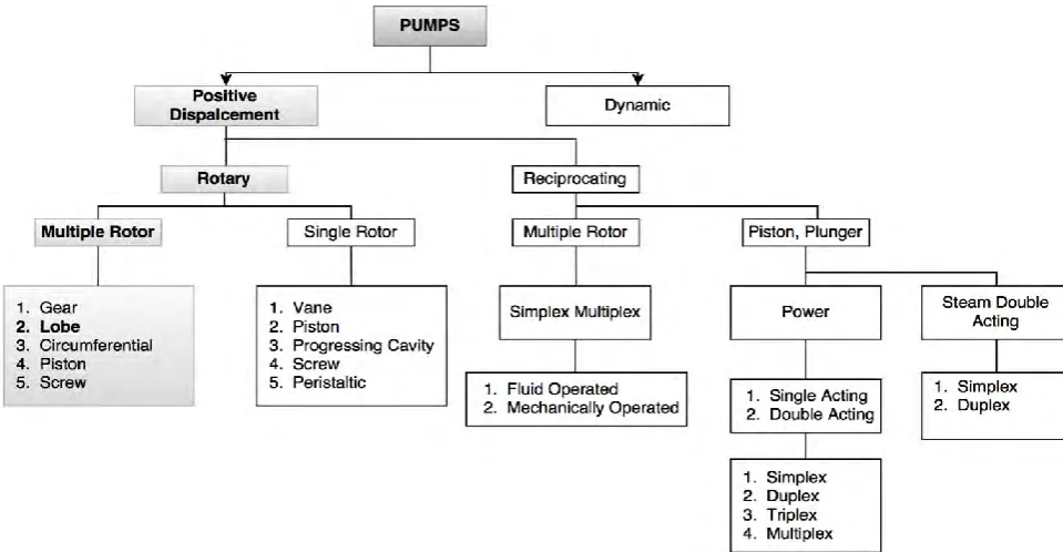
Figure 2.1 : Rotary Pump Family Tree 9
Figure 2.2 : Internal Gear Pump 10
Figure 2.3 : External Gear Pump 10
Figure 2.4 : Sliding Vane Pump 11
Figure 2.5 : Flexible Member Vane Pump 11
Figure 2.6 : Tri-Lobe Pump 12
Figure 2.7 : Circumferential Piston 12
Figure 2.8 : Single Screw Pump 13
Figure 2.9 : Three-Screw Pump 13
Figure 2.10 : Lobe Pump Cycle Process 14
Figure 2.11 : Internal Gear Pump 18
Figure 2.12 : External Gear Pump 20
Figure 2.13 : Lobe Pump 21
Figure 2.14 : Vane Pump 23
Figure 3.1 : Overall Project Process Flow 30
Figure 3.2 : 3D View of Rotors Profile of a Lobe Pump 35
Figure 3.3 : 2D and 3D Cross-Section of Pump Housing and Rotors of a Lobe Pump for Design A 37
Figure 3.4 : CAD Model of a Lobe Pump 38
Figure 3.5 : 3D Cross-Section for Chamber of a Lobe Pump Used for Autodesk CFD Simulation 39
Figure 3.6 : 2D Cross-Section for Rotor of a Lobe Pump (Existing Design) 39
Figure 3.7 : 3D Cross-Section for Chamber of a Lobe Pump Used for Autodesk CFD Simulation 40
Figure 3.8 : 2D Cross-Section for Rotor of a Lobe Pump (Design A) 40
Figure 3.9 : 3D-Cross Section for Chamber of a Lobe Pump Used for Autodesk CFD Simulation 41
Figure 3.10 : 2D Cross-Section for Rotor of a Lobe Pump (Design B) 41
Figure 3.11 : 3D Cross-Section for Chamber of a Lobe Pump Used for Autodesk CFD Simulation 42
Figure 3.12 : 2D Cross-Section for Rotor of a Lobe Pump (Design C) 42
Figure 3.13 : 3D Cross-Section for Chamber of a Lobe Pump Used for Autodesk CFD Simulation 43
Figure 3.14 : 2D Cross-Section for Rotor of a Lobe Pump (Design D) 43
Figure 4.1 : The Relationship Between Volume Flow Rate (m3/s) and the Reynolds Number 51
xi
LIST OF TABLES
Table 2.1 : The Comparing 4 Types of PD Pumps 16
Table 3.1 : Gantt Chart for PSM 1 2015/2016 33
Table 3.2 : Gantt Chart for PSM 2 2015/2016 34
Table 3.3 : Type of Design Rotors Profile of a Lobe Pump 36
Table 3.4 : Appendices List 44
Table 4.1 : Volume Flow Rate (m3/s) 47
Table 4.2 : Type of Fluid Properties 48
1
CHAPTER 1
INTRODUCTION
This chapter will introduce the project. It contains the background, the problem statement, objectives, the scopes of the project and the finally the outline of the report is briefly discussed.
1.1 Background of Study
Lobe pumps are used in a variety of industries including, pulp and paper, chemical, food, beverage, pharmaceutical, and biotechnology (Liu & Lu, 2014). They are popular in these diverse industries because they offer superb sanitary qualities, high efficiency, reliability, corrosion resistance, and good clean-in-place and sterilize-in-place
(CIP/SIP) characteristics. This pump offers a variety of lobe options including double folium, tri-folium and multi-folium (Smith, 2007). Rotary lobe pumps are non-contacting and have large pumping chambers, allowing them to handle solids such as cherries or olives without damage. They are also used to handle slurries, pastes, and a wide variety of other liquids (Tuzson, 2000). If wetted, they offer self-priming performance. A gentle pumping action minimizes product degradation. They also offer reversible flows and can operate dry for long periods of time. Flow is relatively independent of changes in process pressure, so the output is constant and continuous.
[image:16.595.247.396.590.707.2]2
The rotary lobe pump belongs to the positive displacement pump family. It is a dual shaft pump design with external timing gears, allowing two intermeshing rotors to operate synchronously (Tuzson, 2000). The pump operation is similar to the function of a positive displacement blower. By minimizing the clearances between the rotors and the pump casing allow pumping action by forming a seal with the liquid between the suction and discharge side. Most positive displacement pumps need to be operated with elastomers (Liu & Lu, 2014). Since the rotary lobe pump has no preferred rotation direction, it can be operated in a reversible mode.
The basic configuration and working action of a lobe pump assembled with a pair of two lobe rotor (Lich, 2010). Positive fluid displacement is achieved by the continuous rotation of the conjugate rotors. Because the driving rotor of the pump can only drive the driven rotor half cycle, an external driving gear pair is needed in order to provide a continuous output motion (Smith, 2007). To improve the performance of the positive displacement blower, it is imperative to understand the detailed internal flow characteristics or enable a visualization of flow status.
By comparing the experimental measurements and the numerical results on the variation of flow rate with the outlet pressure, the maximum relative error of the flow rate is less than 2.15%, even at the maximum outlet pressure condition, which means that the calculation model and numerical computational method used are effective (Lich, 2010).
3
1.2 Problems Statement
4
1.3 Scope of Study
This project focus on the optimization of existing vortex of 3 elements which is rotating time of gearing ratio position, size and shape of the rotor will use to investigate the effect on final pressure and velocity by using Autodesk CFD Simulation software. The design of the size and shape of the rotor used with the different dimension (Sang & Meng, 2013). In this software the method to produce the part is using an air flow technique which is rotary of vacuum pump. This technique begins with difference shape of rotor folium, which is double folium and tri-folium will be studied. The Autodesk CFD Simulation software was used as 2D air flow simulation tools in order to simulate the behavior of characteristics of part produce with different rotting time and the position (Smith, 2007). After the simulation process completed, the pressure and velocity will be investigated by the software. Finally, the best results of the selection of vortex parameters will be suggested.
1.4 Objectives of Study
1. To conduct literature review on types of rotary pump to determine the differences of functions and applications.
2. To develop 3D CAD model of a lobe pump.
3. To use the Autodesk CFD Simulation to find the optimum parameter of rotating time and positon, size and shape of rotors.
5
1.5 Outline of Report
To complete this project, this following will give a systematic of the report are divided into five chapters, namely:
Chapter 1: Introduction
This chapter is an introduction to the problem that will be in discuss problems such as background of study, problem statement, scope of study, research objectives and systematic writing.
Chapter 2: Literature Review
This chapter is part of the basic theories used in solving and discuss the existing problems. Outlines a summary of the theory that is the basis and general view in theory as a supporter in problem solving based on the existing product of the lobe pump.
Chapter 3: Methodology
This chapter is an outline description of the method research used by the researcher as well as the framework in solve the problem.
Chapter 4: Results and Discussion
This chapter presents the data obtained from the company and journal which is further processed in accordance with the existing material, ie data regarding corrective vortex parameter and data on machine will then be processed by the methods already mentioned above.
Chapter 5: Conclusion
6
CHAPTER 2
LITERATURE REVIEW
This chapter discusses about various literature reviews that serve as a guide in this project. The reviews are from books, journals, articles and conference paper. The major topic reviewed such as vacuum definition, vacuum pump, type of vacuum pump, how lobe pumps work, comparing 4 types of PD pumps, advantages and disadvantages, applications of the lobe pump and Taguchi method approach in finding optimum parameters that will be discussed in this chapter.
2.1 Vacuum Definition
Pressure is generally the result of molecules, within a gas or liquid, impacting on their surroundings usually the walls of the containing vessel (Tuzson, 2000). Its magnitude depends on the force of the impacts over a defined area hence, for example, the Newton per square meter, given the special name Pascal and the traditional (but obsolete) unit pound force per square inch. The relationship between pressure (p), force (F) and area (A) is given by:
P : Pressure (N/m2)
F : Force (N) A : Area (m2)
𝑃 =𝐹
𝐴
7
Definition of vacuum is not precise but it is commonly taken to mean pressures below and often considerably below, atmospheric pressure (John, 2007). It does not have separate units and we do not say that vacuum equals force per unit area. Thus, strictly do not need to talk about both pressure and or vacuum because vacuum is pressure. But the differences are often misunderstood and thus leaving out the word vacuum can falsely imply that the pressure in question is above that of atmospheric pressure.
2.2 Vacuum Pump
Vacuum pumps are used to remove gas molecules in the gas phase from a gas filled volume and to maintain a required degree of gas rarefaction in that volume (John, 2007). A vacuum pump converts the mechanical input energy of a rotating shaft into pneumatic energy by evacuating the air contained within a system. The internal pressure level thus becomes lower than that of the outside atmosphere. The amount of energy produced depends on the volume evacuated and the pressure difference produced. Mechanical vacuum pumps use the same pumping mechanism as air compressors, except that the unit is installed so that air is drawn from a closed volume and exhausted to the atmosphere (John, 2007). A major difference between a vacuum pump and other types of pumps is that the pressure driving the air into the pump is below atmospheric and becomes vanishingly small at higher vacuum levels. Other differences between air compressors and vacuum pumps are:
1. The maximum pressure difference produced by pump action can never be higher than 29.92 in. Hg (14.7 psi), since this represents a perfect vacuum.
2. The mass of air drawn into the pump on each suction stroke, and hence the absolute pressure change, decreases as the vacuum level increases.
8
Chiu and Yu (2015) developed a design method for improving the flow characteristics of a multistage roots pumps, about the research field on the flow characteristics of multistage Roots pumps with serial and parallel connections are investigated. They concluded that the better progression phase angles in the serial and parallel connection designs are 30 and 45, respectively.
Based on the ideas with Sang and Meng (2013), they stated about transient simulation in interior flow field of lobe pump, they focused on the development and control of the double folium and tri-folium lobe pump profiles. They result shows more vortexes in double folium lobe pump.
However, investigated about Prediction of protein shear stress at different pump efficiencies (Tong & Yang, 2000). They also mentioned on simulated in order to predict variations in shear stress and pump efficiency with varying gap size which is 1mm, 2mm, 3mm and 4mm between the lobe and pump housing. The data shows with an increase in the gap width, the pump efficiency drops dramatically.
2.3 Type of Vacuum Pump
9
Figure 2.1: Rotary Pump Family Tree
(From Johann, F. G. 2007. Centrifugal Pumps, 2nd Ed. Springer: Verlag Berlin Heidelberg.)
By definition, PD pumps displace a known quantity of liquid with each revolution of the pumping elements examples gears, rotors, screws, vanes (Zhang & Fong, 2015). PD pumps displace liquid by creating a space between the pumping elements and trapping liquid in the space. The rotation of the pumping elements then reduces the size of the space and moves the liquid out of the pump (John, 2007). PD pumps can handle fluids of all viscosities up to 1,320,000 cSt / 6,000,000 SSU, capacities up to 1,150 m3 / Hr / 5,000 GPM, and pressures up to 700 BAR / 10,000 PSI. Rotary pumps
[image:24.595.71.551.86.335.2]