Adaptive Space-Time Equalisation for Multiple-Antenna Assisted Multiple-Input
Multiple-Output Systems
A. Livingstone and S. Chen
School of Electronics and Computer Science University of Southampton, Southampton SO17 1BJ, U.K.
E-mails:{al902, sqc}@ecs.soton.ac.uk
ABSTRACT
This paper investigates an adaptive space-time equalisation (STE) assisted multiuser detection scheme for multiple-antenna aided multiuser systems. A minimum bit error rate (MBER) de-sign is compared with the standard minimum mean square error (MMSE) design. It is shown that the MBER design provides signif-icant performance enhancement, in terms of achievable system bit error rate, over the MMSE design for the multiple-antenna assisted multiple-input multiple-output communication scenario. Adaptive implementation of the MBER STE is realised using a stochastic gra-dient based least bit error rate algorithm, which is demonstrated to consistently outperform the adaptive least mean square based STE.
I. INTRODUCTION
Mobile wireless system designers are increasingly faced with a number of challenges, including limited bandwidth, a hostile, time-varying propagation channel and ever increasing pressure to im-prove capacity and data rates. Smart antenna aided space-time pro-cessing is capable of substantially improving the achievable wire-less system capacity, coverage and quality by suppressing the ef-fects of both intersymbol interference and co-channel interference [1]-[12]. We consider the multiple-input multiple-output (MIMO) system based on a space division multiple access (SDMA) scheme, where each transmitter employs a single antenna, while the receiver has multiple antennas. To interpret the multiuser supporting capa-bility of such an SDMA based MIMO system [13], it is useful to compare it with classic code division multiple access (CDMA) mul-tiuser systems [10]. In a CDMA system, each user is separated by a unique user-specific spreading code. By contrast, an SDMA system differentiates each user by the unique user-specific channel impulse response (CIR) encountered at the receiver antennas. In this anal-ogy, the unique user-specific CIR plays the role of a user-specific CDMA signature. However, owing to the non-orthogonal nature of the CIRs, an effective multiuser detection (MUD) is required for separating the users in an SDMA based MIMO system.
We investigate a space-time equalisation (STE) based multiuser detection (MUD) for SDMA based MIMO systems. The most pop-ular MIMO-receiver design is constituted by the minimum mean square error (MMSE) MUD [9]-[11],[14]. We investigate a mini-mum bit error rate (MBER) design for the STE based MUD, and we show that the MBER STE design is superior in comparison to the MMSE design in terms of achievable bit error rate (BER). This is significant, since the MMSE design is often considered to be the state-of-the-art technique in multiple antenna assisted systems [9]-[11],[14]. Our study thus demonstrates that the system capacity can further be enhanced beyond that of the MMSE solution. We also
study an adaptive implementation of the MBER STE based MUD, known as the least bit error rate (LBER). Our simulation results demonstrate that the LBER STE aided MUD consistently outper-forms the adaptive least mean square (LMS) based one.
II. SYSTEMMODEL
The system model investigated is the multiple antenna aided SDMA based MIMO system supportingM users, as depicted in Fig. 1, where each of theMusers is equipped with a single transmit antenna and the receiver is assisted by anL-element antenna array. The symbol-rate received signal samplesxl(k)for1≤l ≤Lare given by [9],[15]
xl(k) = M X m=1
nC−1
X i=0
ci,l,msm(k−i)+nl(k) = ¯xl(k)+nl(k), (1)
wherenl(k) is a complex-valued additive white Gaussian noise withE[|nl(k)|2] = 2σ2n,x¯l(k)denotes the noise-free part of the
lth receive antenna’s output,sm(k)is thekth transmitted symbol of userm, cl,m = [c0,l,mc1,l,m· · ·cnC−1,l,m]
T
denotes the tap vector of the CIR connecting the usermand thelth receive an-tenna, andnCis the length of the CIR. Binary phase shift keying modulation is employed and hencesm(k)∈ {±1}.
The MUD consists of a bank of theMSTEs, as shown in Fig. 2. The outputs of theMdetectors are given by
ym(k) = L X
l=1
nF−1
X i=0
w∗i,l,mxl(k−i), 1≤m≤M, (2)
user 1
user 2
user M
Multiuser Detector
Tx
Tx
Tx
...
...
...
...
...
+
+
+
n (k) s (k)
x (k)
n (k)L s (k)
M
x (k)
x (k) n (k)
1
s (k−d)1 1
1
s (k)
y (k) 2
2
2
L
M y (k) y (k) 1
2
^
s (k−d)2 ^
[image:1.595.306.545.499.699.2]s (k−d)M ^
X X
X
...
...
...
+
+ +
X
...
+
...
...
+
+ X X
...
...
x (k)
x (k)L x (k)1
∆ ∆ ∆
∆ ∆
∆
∆ ∆ ∆
w
X X
0,1,m* w* wn −1,1,m*
w0,2,m* w1,2,m* wn −1,2,m*
w0,L,m* w1,L,m* w
*
y (k)
+ X 2
m 1,1,m
n −1,L,mF
F
[image:2.595.68.269.92.256.2]F
Fig. 2. STE assisted MUD for userm, where∆denotes the symbol-spaced delay,L is the number of receive antennas,1≤m≤M, andMis the number of users. wherewl,m = [w0,l,m w1,l,m· · ·wnF−1,l,m]
T
denotes the mth user detector’s equaliser weight vector for thelth receive antenna, andnFis the length of temporal equaliser filter. TheMuser detec-tors’ decisions are defined by
ˆ
sm(k−d) =sgn(yRm(k)),1≤m≤M, (3)
where ˆsm(k − d) is the estimate of sm(k −d), yRm(k) = <[ym(k)], anddis the detector decision delay.
Let us define thenF×(nF+nC−1)CIR convolution matrix associated with the usermandlth receive antenna as
Cl,m=
c0,l,m · · · cnC−1,l,m 0 · · · 0
0 c0,l,m · · · cnC−1,l,m
. .. ... ..
. . .. . .. . .. . .. 0
0 · · · 0 c0,l,m · · · cnC−1,l,m
(4) and introduce the overall system CIR convolution matrix as
C=
C1,1 C1,2 · · · C1,M C2,1 C2,2 · · · C2,M
..
. ... · · · ... CL,1 CL,2 · · · CL,M
. (5)
Then the received signal vectorx(k)can be expressed by
x(k) =C s(k) +n(k) = ¯x(k) +n(k), (6)
where
x(k) = [xT1(k)x2T(k)· · ·xTL(k)]T (7)
withxl(k) = [xl(k)xl(k−1)· · ·xl(k−nF+ 1)]T,
n(k) = [nT1(k)n2T(k)· · ·nTL(k)]T (8)
withnl(k) = [nl(k)nl(k−1)· · ·nl(k−nF+ 1)]T, and
s(k) = [sT1(k)s2T(k)· · ·sTM(k)]T (9)
withsm(k) = [sm(k)sm(k−1)· · ·sm(k−nF−nC+ 2)]T. Let us further define
wm= [w1T,mwT2,m· · ·wTL,m]T
. (10)
Then the output of themth detector can be written as
ym(k) = L X
l=1
wHl,mxl(k) =wHmx(k)
= wHm(¯x(k) +n(k)) = ¯ym(k) +em(k), (11)
where em(k) is Gaussian distributed, having a zero mean and
E[|em(k)|2] = 2wmHwmσ2n.
III. SPACE-TIMEEQUALISATION
The task of designing the STE (11) is to choose an optimal weight vectorwmaccording to some design criterion.
A. Minimum Mean Square Error Design
Classically, themth STE detector’s weight vectorwmis deter-mined by minimising the mean square error metric ofE[|sm(k−
d)−ym(k)|2], which leads to the following MMSE solution [9]-[11],[14]
w(MMSE)m= C CH+ 2σn2I −1
C|(m−1)(n
F+nC−1)+(d+1), (12) for1≤m≤M, whereIdenotes theLnF×LnFidentity matrix andC|itheith column ofC. An adaptive implementation of the MMSE solution can readily be realised using the LMS algorithm [16]-[18]
wm(k+ 1) =wm(k) +µ(sm(k−d)−ym(k))∗x(k), (13)
whereµis the step size.
B. Minimum Bit Error Rate Design
As recognized by [19] in a CDMA context and by [20] in a beamforming-based MUD scenario, a better strategy is to choose the detector’s coefficients by directly minimising the system’s BER. A main objective of this study is to investigate the MBER solu-tion for the STE based MUD (11). Following the notasolu-tions used in [19],[20], let us denote theNs = 2M(nF+nC−1)number of pos-sible transmitted symbol sequences ofs(k)ass(q),1 ≤q ≤Ns. Denote furthermore the((m−1)(nF+nC−1)+(d+1))th element ofs(q), corresponding to the desired symbolsm(k−d), ass(
q)
m,d. The noise-free part of themth detector input signalx¯(k)assumes values from the vector signal set defined as
Xm={x¯(q)=C s(q),1≤q≤Ns}. (14)
Similarly, the noise-free part of themth detector’s outputy¯m(k) assumes values from the scalar setYm ={y¯(mq) =wHmx¯(q),1≤
q≤Ns}. Thusy¯Rm(k) =<[¯ym(k)]can only take the values from the set
YRm={y¯
(q)
Rm =<[¯y
(q)
andYRm can be divided into the two subsets conditioned on the value ofsm(k−d)
YR(±m)={y¯
(q,±)
Rm ∈ YRm:sm(k−d) =±1}. (16)
The probability density function (PDF) ofyRm(k)is a Gaussian mixture defined by
pm(yR) =
1 Ns
Ns
X q=1
1
p
2πσ2
nwHmwm
e−
yR−y¯
(q)
Rm
2 2σ2nwH
mwm
, (17)
wherey¯R(q)
m ∈ YRm. Thus the BER of themth detector associated with the detector’s weight vectorwmcan be shown to be [19],[20]
PE(wm) =
1 Ns
Ns
X q=1
Q g(q)(wm), (18)
where
Q(u) = √1
2π
Z ∞
u
e−v 2
2 d v (19)
and
g(q)(wm) = sgn(s (q)
m,d)¯y
(q)
Rm
σn p
wH mwm
. (20)
Note that the BER is invariant to a positive scaling ofwm.
The MBER solution for themth STE detector is then defined as the weight vector that minimises the error probability (18)
w(MBER)m= arg min
wm
PE(wm). (21)
The gradient ofPE(wm)with respect towmis given by
∇PE(wm) =
1
2Ns √
2πσn p
wH mwm
Ns
X q=1
e− ¯
y(q) Rm
2 2σ2nwH
mwm
×sgns(m,dq) y¯ (q)
Rmwm wH
mwm −
¯
x(q) !
. (22)
Given the gradient (22), the optimisation problem (21) can be solved iteratively by commencing the iterations from an appropriate initial point using a gradient-based optimisation algorithm, such as the simplified conjugate gradient algorithm [19],[20],[21].
Following the derivations presented in [19],[20], an adaptive im-plementation of the MBER STE based MUD can be realised using the LBER algorithm which takes the form of
wm(k+ 1) =wm(k) +µ
sgn(sm(k−d))
2√2πρn
e−
y2 Rm(k)
2ρ2n x(k). (23)
The adaptive gainµand the kernel widthρnare the two algorithmic parameters that have to be set appropriately to ensure a fast conver-gence rate and small steady-state BER misadjustment.
IV. SIMULATIONSTUDY
The simulations was carried out using MATLAB.
A. Stationary System
The systems used in the simulation supportedM = 3users with
L= 2andL= 4receiver antennas. All the three users had an equal transmit power. TheM×L= 6(forL= 2) andM×L= 12(for
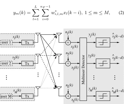
L= 4) CIRs are listed in Table I, each CIR havingnC= 2taps. In the actual simulation, all the CIRs were normalised to provide unit channel energy, i.e.kcl,mk2 = 1for alllandm. Each equaliser temporal filter had a length ofnF = 3and the detector decision delay was chosen to bed = 1. Fig. 3 compares the BER perfor-mance of the MMSE and MBER STE based MUDs. The BER of a STE based MUD was computed using the theoretic BER formula (18), the MMSE STE weight vector was calculated using the for-mula (12), and the MBER STE solution was computed numerically using the simplified conjugate gradient algorithm. It can be seen that for bothL = 2andL = 4as well as for all three users the MBER STE detectors had better BER performance than the corre-sponding MMSE detectors. By comparing Fig. 3 (a)-(c) with Fig. 3 (d)-(f), it confirms that the system withL = 4antennas achieved better performance than the system withL= 2antennas.
The LMS and LBER adaptive STE based MUDs were investi-gated in simulation, and the BERs of the both LMS and LBER MUDs, after training convergence and averaging over 30 runs, are compared in Fig. 4, where better performance of the adaptive LBER detectors over the corresponding LMS ones is self evident. The step size for the LMS algorithm was chosen asµ = 0.01, while for the LBER algorithm the step sizeµ= 0.1and the kernel width
ρn= 4σn.
B. Slow Fading System
The system again supportedM = 3users withL= 2andL= 4
antennas. However, fading channels were simulated and moreover each CIR hadnC = 3taps. The CIR coefficients were generated using a Doppler fading process with Rayleigh distributed magni-tudes, normalised to unit power. The coefficients were varied every symbol period. The process used was based on the Clarke and Gans fading model, as described in [15],[22],[23]. Each equaliser tem-poral filter had a length ofnF = 5and the detector decision delay was set tod = 2. The transmission frame structure consisted of 50 training symbols followed by 450 data symbols. In the simula-tions, the normalised Doppler frequency for the simulated system was10−5, which for a carrier of 900 MHz and a symbol rate of
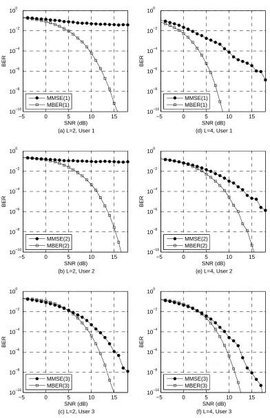
3 Msymbols/s corresponded to a user velocity of 10 m/s (36 km/h). The step size for the LMS algorithm was chosen asµ = 0.005, while for the LBER algorithm the step sizeµ = 0.1and the ker-nel widthρn = 4σn. The BER of an adaptive STE based MUD was calculated using Monte Carlo simulation. Fig. 5 compares the BERs of the LBER STE based MUDs with those of the LMS based ones. It can be seen from Fig. 5 that the LBER STE based MUD consistently outperformed the LMS STE based MUD for all three users and in both the cases ofL= 2andL= 4antennas.
V. CONCLUSIONS
cl,m l= 1 l= 2 l= 3 l= 4
m= 1 -0.5+0.4j, 0.7+0.6j 0.5-0.4j, -0.8-0.3j 0.4-0.4j, -0.7-0.8j 0.5+0.5j, 0.6-0.9j
m= 2 -0.1-0.2j, 0.7+0.6j -0.3+0.5j, -0.7-0.9j -0.1-0.2j, 0.7+0.6j -0.6-0.4j, 0.9-0.4j
m= 3 -0.7+0.9j, 0.6+0.4j -0.6+0.8j, -0.6-0.7j 0.3-0.5j, 0.9+0.1j -0.6-0.6j, 0.8+0.0j
TABLE I
CIRS USED IN THE STATIONARY SYSTEM SIMULATION.
STE assisted MUD can obtain significant performance gains over the standard MMSE design, in terms of achievable system BER. Adaptive implementation of the MBER STE assisted MUD has been considered using the LBER algorithm. The simulation results have demonstrated that the adaptive LBER STE assisted MUD con-sistently achieves better BER performance over the classical LMS STE assisted MUD.
REFERENCES
[1] J.H. Winters, J. Salz and R.D. Gitlin, “The impact of antenna diversity on the capacity of wireless communication systems,”
IEEE Trans. Communications, Vol.42, No.2, pp.1740–1751,
1994.
[2] A.J. Paulraj and C.B. Papadias, “Space-time processing for wireless communications,” IEEE Signal Processing Magazine, Vol.14, No.6, pp.49–83, 1997.
[3] L.C. Godara,“Applications of antenna arrays to mobile com-munications, Part I: Performance improvement, feasibility, and system considerations,” Proc. IEEE, Vol.85, No.7, pp.1031– 1060, 1997.
[4] J.H. Winters, “Smart antennas for wireless systems,” IEEE
Per-sonal Communications, Vol.5, No.1, pp.23–27, 1998.
[5] S.N. Diggavi, “On achievable performance of spatial diver-sity fading channels,” IEEE Trans. Information Theory, Vol.47, No.1, pp.308–325, 2001.
[6] P. Vandenameele, L. van Der Perre and M. Engels, Space
Divi-sion Multiple Access for Wireless Local Area Networks. Boston:
Kluwer Academic Publishers, 2001.
[7] S. Bellofiore, C.A. Balanis, J. Foutz and A.S. Spanias, “Smart-antenna systems for mobile communication networks. Part 1. Overview and antenna design,” IEEE Antennas and
Propaga-tion Magazine, Vol.44, No.3, pp.145–154, 2002.
[8] J.S. Blogh and L. Hanzo, Third Generation Systems and
In-telligent Wireless Networking – Smart Antenna and Adaptive Modulation. Chichester: John Wiley, 2002.
[9] A. Paulraj, R. Nabar and D. Gore, Introduction to Space-Time
Wireless Communications. Cambridge: Cambridge University
Press, 2003.
[10] L. Hanzo, L-L. Yang, E-L. Kuan and K. Yen, Single- and
Multi-Carrier DS-CDMA: Multi-User Detection, Space-Time Spreading, Synchronisation, Standards and Networking. IEEE
Press - John Wiley, 2003.
[11] A.J. Paulraj, D.A. Gore, R.U. Nabar and H. B ¨olcskei, “An overview of MIMO communications – A key to gigabit wire-less,” Proc. IEEE, Vol.92, No.2, pp.198–218, 2004.
[12] S.N. Diggavi, N. Al-Dhahir, A. Stamoulis and A.R. Calder-bank, “Great expectations: the value of spatial diversity in wire-less networks,” Proc. IEEE, Vol.92, No.2, pp.219–270, 2004. [13] L. Hanzo, M. M ¨unster, B.J. Choi and T. Keller, OFDM and
MC-CDMA. West Sussex, England: John Wiley and IEEE
Press, 2003.
[14] D.N.C. Tse and S.V. Hanly, “Linear multiuser receivers: effec-tive interference, effeceffec-tive bandwidth and user capacity,” IEEE
Trans. Information Theory, Vol.45, No.2, pp.641–657, 1999.
[15] T.S. Rappaport, Wireless Communications: Principles and
Practice. Upper Saddle River, N.J.: Prentice Hall, 1996.
[16] B. Widrow, J.M. McCool and M. Ball, “The complex lms al-gorithm,” Proc. IEEE, Vol.63, No.4, pp.719–720, 1975. [17] B. Widrow and S.D. Strearns, Adaptive Signal Processing.
En-glewood Cliffs, N.J.: Prentice Hall, 1985.
[18] E. Soria, J. Calpe, J. Chambers, M. Martinez, G. Camps and J.D.M. Guerrero, “A novel approach to introducing adaptive fil-ters based on the LMS algorithm and its variants,” IEEE Trans.
Education, Vol.47, No.1. pp.127–133, 2004.
[19] S. Chen, A.K. Samingan, B. Mulgrew and L. Hanzo, “Adap-tive minimum-BER linear multiuser detection for DS-CDMA signals in multipath channels,” IEEE Trans. Signal Processing, Vol.49, No.6, pp.1240–1247, 2001.
[20] S. Chen, N.N. Ahmad and L. Hanzo, “Adaptive minimum bit error rate beamforming,” IEEE Trans. Wireless
Communica-tions, Vol.4, No.2, pp.341–348, 2005.
[21] M.S. Bazaraa, H.D. Sherali and C.M. Shetty, Nonlinear
Pro-gramming: Theory and Algorithms. New York: John Wiley,
1993.
[22] W.C. Jakes, Microwave Mobile Communications. John Wiley and Sons, 1974.
−5 0 5 10 15 10−10
10−8 10−6 10−4 10−2 100
SNR (dB) (a) L=2, User 1
BER
MMSE(1) MBER(1)
−5 0 5 10 15
10−10 10−8 10−6 10−4 10−2 100
SNR (dB) (b) L=2, User 2
BER
MMSE(2) MBER(2)
−5 0 5 10 15
10−10 10−8 10−6 10−4 10−2 100
SNR (dB) (c) L=2, User 3
BER
MMSE(3) MBER(3)
−5 0 5 10 15
10−10 10−8 10−6 10−4 10−2 100
SNR (dB) (d) L=4, User 1
BER
MMSE(1) MBER(1)
−5 0 5 10 15
10−10 10−8 10−6 10−4 10−2 100
SNR (dB) (e) L=4, User 2
BER
MMSE(2) MBER(2)
−5 0 5 10 15
10−10 10−8 10−6 10−4 10−2 100
SNR (dB) (f) L=4, User 3
BER
[image:5.595.96.487.94.695.2]MMSE(3) MBER(3)
−5 0 5 10 15 10−10
10−8 10−6 10−4 10−2 100
SNR (dB) (a) L=2, User 1
BER
MMSE(1) MBER(1)
−5 0 5 10 15
10−10 10−8 10−6 10−4 10−2 100
SNR (dB) (b) L=2, User 2
BER
MMSE(2) MBER(2)
−5 0 5 10 15
10−10 10−8 10−6 10−4 10−2 100
SNR (dB) (c) L=2, User 3
BER
MMSE(3) MBER(3)
−5 0 5 10 15
10−10 10−8 10−6 10−4 10−2 100
SNR (dB) (d) L=4, User 1
BER
MMSE(1) MBER(1)
−5 0 5 10 15
10−10 10−8 10−6 10−4 10−2 100
SNR (dB) (e) L=4, User 2
BER
MMSE(2) MBER(2)
−5 0 5 10 15
10−10 10−8 10−6 10−4 10−2 100
SNR (dB) (f) L=4, User 3
BER
[image:6.595.96.488.85.692.2]MMSE(3) MBER(3)
−5 0 5 10 15 10−5
10−4 10−3 10−2 10−1 100
SNR (dB) (a) L=2, User 1
BER
LMS(1) LBER(1)
−5 0 5 10 15
10−5 10−4 10−3 10−2 10−1 100
SNR (dB) (b) L=2, User 2
BER
LMS(2) LBER(2)
−5 0 5 10 15
10−5 10−4 10−3 10−2 10−1 100
SNR (dB) (c) L=2, User 3
BER
LMS(3) LBER(3)
−5 0 5 10 15
10−5 10−4 10−3 10−2 10−1 100
SNR (dB) (d) L=4, User 1
BER
LMS(1) LBER(1)
−5 0 5 10 15
10−5 10−4 10−3 10−2 10−1 100
SNR (dB) (e) L=4, User 2
BER
LMS(2) LBER(2)
−5 0 5 10 15
10−5 10−4 10−3 10−2 10−1 100
SNR (dB) (f) L=4, User 3
BER
[image:7.595.99.490.80.692.2]LMS(3) LBER(3)
Fig. 5. BER comparison of the adaptive LMS and LBER STE based MUDs for a 3-userL-antenna system, with Doppler-faded time-varying CIRs. Normalised Doppler frequency