Iterative Soft Interference Cancellation Aided
Minimum Bit Error Rate Uplink Receiver Beamforming
S. Tan, L. Xu, S. Chen, and L. Hanzo School of Electronics and Computer Science University of Southampton, Southampton, SO17 1BJ, U.K.
{st104r,lx04r,sqc,lh}@ecs.soton.ac.uk
Abstract— Iterative multiuser receivers constitute an effective solution for transmission over Multiple Access Interference (MAI) infested chan-nels, when invoking a combined multiuser detector and channel decoder. Most reduced-complexity methods in this area use the Complex-valued Minimum Mean Squared Error (CMMSE) Multiuser Detector (MUD). Since the desired output of BPSK systems is real-valued, minimizing the Mean Square Error (MSE) between the beamformer’s desired output and the real part of the beamformer output has the potential of significantly improving the attainable Bit Error Rate (BER) performance. We refer to this MMSE design as the Real-valued MMSE (RMMSE) receiver. In this paper, we explore a new Soft-Input Soft-Output (SISO) interference cancellation multiuser detection algorithm based on the novel Minimum BER (MBER) criterion. We demonstrate that the MBER turbo receiver outperforms both the CMMSE and the RMMSE algorithms, particularly in so-called ‘overloaded’ beamforming systems, where the number of receiver antennas is lower than the number of users supported.
I. INTRODUCTION
The increasing demand for mobile communication services sup-ported within a limited radio-frequency bandwidth motivates the design of antenna array assisted beamforming techniques [1] as well as Spatial Division Multiple Access (SDMA) arrangements [2]. By appropriately combining the signals received by the different elements of an antenna array, beamforming becomes capable of creating an angularly selective transmitter/receiver beam, hence potentially separating signals transmitted on the same carrier frequency but arriving from sufficiently different angles.
Since the discovery of turbo codes [3], iterative detection [4] has been applied in the context of joint channel estimation and equalization [5], in multiuser detection [6] and numerous other coded communication systems [7]–[9]. In iterative multiuser receivers, the MUD and the channel decoder exchange extrinsic information in a number of consecutive iterations. During each iteration, the extrinsic information extracted from both the MUD and the channel decoder is used as the a prioriinput by the other stage in the next iteration. The information exchanged is exploited for the sake of improving the receiver’s attainable performance. In [7], a suboptimal linear MUD was introduced, which benefitted from both soft interference cancellation and instantaneous linear minimum mean squared error filtering.
Against this background, in this contribution we propose a novel iterative beamforming receiver. The conventional beamformer com-bines the signals received with the aid of each antenna element for the sake of minimizing the MSE between the complex-valued locally stored and received reference signal. We will refer to this MMSE solution as the Complex-valued MMSE (CMMSE) scheme.
The insightful suggestions of Volker K¨uhn are gratefully acknowledged. Furthermore, the financial support of the EPSRC, UK and the European Union in the framework of the Phoenix as well as Newcom projects is thankfully acknowledged by the authors.
For BPSK systems, however, the beamformer’s desired output is real-valued. By minimizing the MSE between the beamformer’s desired output and the real part of the beamformer output, the achievable system’s BER performance can significantly be enhanced [10]. We will refer to this alternative MMSE design as the Real-valued MMSE (RMMSE) arrangement in order to contrast it with the standard CMMSE. However, the CMMSE and RMMSE algorithms do not guarantee the direct and explicit minimization of the system’s BER, despite the monotonous relationship of the MSE and the BER. Hence in references [11]–[13] the BER rather /local/st104rthan the MSE was minimized at the MUD’s output. The Minimum BER (MBER) beamforming design is the true optimal solution and hence it generally outperforms the CMMSE and the RMMSE solutions, particularly in the context of the so-called ‘overloaded’ systems, where the degree of freedom of the antenna array is lower than the number of users. The achievable BER difference of the MMSE and MBER receivers becomes particularly dramatic in this scenario.
The structure of this contribution is as follows. In Section II, we outline the signal model used, followed by the portrayal of our iterative beamformer design. The focus of Section III is the Soft-In Soft-Out (SISO) interference canceller advocated. Our simulation results are presented in Section IV, followed by our conclusions in Section V.
II. SYSTEMDESCRIPTION
A. Signal Model
The system supportsKusers, and each user transmits his/her signal on the same carrier frequency ofω= 2πf. The receiver is equipped with a linear antenna array consisting ofLelements, which have a uniform element spacing ofλ/2, as shown in Fig. 1, whereλis the wavelength. Assume that the channel is non-dispersive in both the angular and the time domain and hence does not induce Intersymbol Interference (ISI). Then the symbol-rate received signal samples can be expressed as
rl(n) = K
k=1
Aksk(n)ejωtl(θk)+nl(n) (1)
for1≤l≤L, whereAkis the non-dispersive complex-valued channel coefficient of user k, sk(n) is the nth symbol of user k, nl(n) is a complex-valued Gaussian white noise process associated with
E[|nl(n)|2] = 2σn2, and
tl(θk) = λ
2(l−1) sin(θk)/c (2) is the relative time delay at array elementlfor the source signal of user k, with θk being the Line Of Sight (LOS) angle of arrival for sourcek, and cis the speed of light.
/2 /2 1 L-1
L 2
user k
k
Fig. 1. Geometric structure of the antenna array showing the received signal of userk, whereθkis the LOS component’s angle of arrival
If source k is the desired user and the rest of the sources are the interfering users, then the desired-user’s Signal to Noise Ratio becomes SNRk =|Ak|2σ2
s/2σ2n and the deschoberrsired Signal to Interference Ratio of user k′
is SIRk,k′ = |Ak|2/|Ak′|2, where σ2
s = 1 is the symbol energy. The received signal vector r(n) = [r1(n) r2(n)· · ·rL(n)]T
is given by
r(n) =Hs(n) +n(n), (3)
where we have n(n) = [n1(n) n2(n)· · ·nL(n)]T, the
transmitted symbol vector of the K users is s(n) =
[s1(n) s2(n)· · ·sK(n)]T
, and the system matrix is denoted byH= [h1 h2· · ·hK]which is associated with the steering vector hk= [Akejωt1(θk) A
kejωt2(θk)· · ·AkejωtL(θk)]T for source k. B. Iterative Multiuser Beamforming Receiver Structure
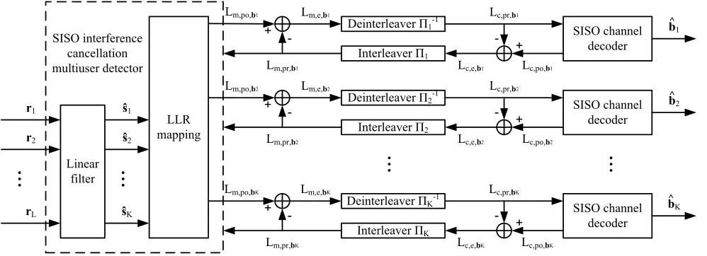
The iterative multiuser beamforming receiver’s structure is shown in Fig. 2, which consists of two stages, namely the SISO interference cancellation aided beamforming multiuser detector, followed by K
parallel single-user SISO channel decoders. The two stages are separated by the usual deinterleavers and interleavers.
The proposed SISO beamforming MUD first computes the esti-mated symbol ˆsk corresponding to the transmitted symbolsk using a linear filter, which determines the coefficients of the beamformer weight w according to the specific design criterion employed and
uses this weight to estimate ˆsk from the received signal rwith the aid of a linear transformation [6]. Let us now definebk(n, i)as theith bit of symbolsk(n), whereasbk(j)is the same bit but in a different position of the bit-based interleaving block after the deinterleaver. The indicesmand care associated with the multiuser detector and channel decoder, respectively, and the indicespr,poandeare used for the a priori, a posteriori and extrinsic information. Then the SISO beamforming MUD delivers thea posterioriinformation of bit
bk(n, i)expressed in terms of its Log-Likelihood Ratio (LLR) as [4]
Lm,po,bk(n,i)= ln
P[bk(n, i)=0|ˆsk(n)] P[bk(n, i)=1|ˆsk(n)] = lnP[ˆsk(n)|bk(n, i)=0]
P[ˆsk(n)|bk(n, i)=1]+ ln
P[bk(n, i)=0] P[bk(n, i)=1] =Lm,e,bk(n,i)+Lm,pr,bk(n,i), (4) where the second term, denoted by Lm,pr,bk(n,i), represents the a
prioriLLR of the interleaved and Recursive Systematic Convolutional (RSC) encoded bitbk(n, i). For the first iteration, assuming equiprob-able RSC encoded bits, i.e. that noa prioriinformation is available, all bits have a probability of0.5. Hence in the LLR domain we have
Lm,pr,bk(n,i) = 0. The first term in Equation (4), which is denoted
byLm,e,bk(n,i), represents the extrinsic information delivered by the
SISO multiuser detector, based on the received signal r(n) and on
the a priori information about the RSC encoded bits of all users, except the ith bit of the desired userk. The extrinsic information, which is not influenced by the a priori information of the desired
bitiprovided by thekth channel decoder, is then deinterleaved and fed into thekth user’s channel decoder, which will be used as thea prioriinformation in the next iteration.
As seen in Fig. 2, between the banks of channel decoders and interleavers, based on the a prioriinformationLc,pr,bk(j) provided
by the SISO beamforming MUD for the SISO decoder, we compute the extrinsic LLR as [4]
Lc,e,bk(j)=Lc,po,bk(j)−Lc,pr,bk(j), (5)
where the extrinsic information is gleaned from the surrounding RSC encoded bits, excluding the specific bit considered [5]. We note that as usual in joint iterative detection and decoding schemes [5], we exchange the extrinsic information concerning both the original information bits and parity bits, rather than only that of the information bits, although only the LLRs of the latter are needed in the classic turbo decoder of Berrouet al.[3]. After interleaving, the extrinsic information delivered by the channel decoders is then fed back to the SISO multiuser detector, as thea prioriinformation concerning the RSC encoded bits of all the users for exploitation during the next iteration.
At the first iteration, the extrinsic information contributions
Lm,e,bk and Lc,e,bk are statistically independent. However, during
the subsequent iterations they will become more and more correlated and hence the incremental iteration gains become more modest.
III. SISO INTERFERENCECANCELLATION
As described in the previous section, the task of SISO interference cancellation is to choose the beamformer weight w of the linear
filter seen in Fig. 2 according to an appropriate design criterion and compute the corresponding output LLRs.
Given thea prioriLLRs, we first define the mean and covariance of thekth user’s symbols as [8]
¯
sk= E[sk] =
q
s(kq)·P(sk=s
(q)
k )
=
tanh(Lpr,bk(1)
2 ), BPSK
tanh(Lpr,bk(1)
2 ) +jtanh(
Lpr,bk(2)
2 )
√
2 , QPSK
(6)
and
vk= Cov[sk, sk] = E[sks
∗
k]−E[sk]E[s∗k]
=
1−tanh2(Lpr,bk(1)
2 ), BPSK
1−tanh
2(Lpr,bk(1)
2 ) + tanh
2(Lpr,bk(2)
2 )
2 , QPSK ,
(7)
wheres(kq) is theqth legitimate value of the symbolsk. When using the soft interference cancellation principle, the estimated symbol of userkcan be expressed as [8]
ˆ
sk= ¯sk+vkwHk(r−H¯s), (8) where we have¯s= [¯s1s2¯ · · ·¯sK]T.
A. SISO Interference Cancellation Using the Complex-Valued MMSE MUD
Classically, the beamformer’s weight vector wk is determined by
minimizing the complex-valued MSE metric of [1]
[image:2.595.313.565.431.590.2]Deinterleaver1-1
Interleaver1
SISO channel decoder
Linear filter
Lm,po,b1 Lc,pr,b1
Lm,pr,b1
Lm,e,b1
Lc,po,b1
Lc,e,b1 +
-+
-r1
r2
rL
Deinterleaver2-1
Interleaver2
SISO channel decoder
Lm,po,b2 Lc,pr,b2
Lm,pr,b2
Lm,e,b2
Lc,po,b2
Lc,e,b2 +
+
-DeinterleaverK-1
Interleaver K
SISO channel decoder
Lm,po,bK Lc,pr,bK
Lm,pr,bK
Lm,e,bK
Lc,po,bK
Lc,e,bK +
-+
-LLR mapping
Æ1
Æ2
Æ
K SISO interference
cancellation multiuser detector
b2 ^ b1 ^
bK ^
-Fig. 2. Iterative multiuser beamforming receiver structure
Using Equation (8) and setting the gradient ofJcmse(wk)in
Equa-tion (9) to zero leads to the closed-form CMMSE soluEqua-tion of [8]
wk,cmmse= (HVHH+ 2σ2
nIL)
−1h
k, (10)
where IL denotes the (L×L)-dimensional identity matrix and we
haveV= diag[v1 v2· · ·vK].
As stated in [8], the conditional PDF P[ˆsk|sk=s(kq)] can be assumed to be Gaussian distributed and the extrinsic output LLRs are given by
Le,bk(1)=
4ℜ[wH
k(r−H¯s+ ¯skhk)] 1−vkwkHhk
(11)
for BPSK, and
Le,bk(1)=
2√2ℜ[wH
k(r−H¯s+ ¯skhk)] 1−vkwHkhk
, (12)
Le,bk(2)=
2√2ℑ[wH
k(r−H¯s+ ¯skhk)] 1−vkwkHhk
(13)
for QPSK.
B. SISO Interference Cancellation Using the Real-Valued MMSE MUD
For BPSK systems, the beamformer’s desired output sk is real-valued. It is clear that the CMMSE solution of Section III-A attempts to simultaneously minimize the MSE between the desired signal and both the real part and imaginary part of the beamformer’s output. However, in case of BPSK modulation the beamformer’s decision depends only on the real part. Minimizing the MSE associated with the imaginary part does not contribute to improving the beamformer’s performance. Rather it imposes an unnecessary constraint on the beamforming weight [10]. Hence we introduce the RMMSE solution. The real-valued MSE cost function minimizing the MSE between the desired signal and the real part of the beamformer’s output can be written as
Jrmse(wk) = E[(sk−ˆsk,R)2], (14)
wheresˆk,R=ℜ[ˆsk]. The RMMSE solution is defined by
wk,rmmse= arg min
w
Jrmse(wk). (15)
The gradient ofJrmse(wk)is
∇Jrmse(wk) =−2v2
khk+v2k(HVHH+ 2σ2nIL)wk +v2kHVHTw
∗
k. (16)
It is seen in Equation (16) that there exists no closed-form solution for this RMMSE design. Fortunately, we can apply the real-valued vertical concatenation matrix method [10] to resolve this problem. Let us define the indexc as the subscript to indicate the matrices’ vertical concatenation, then we have
Mc=
ℜ[M]
ℑ[M]
, (17)
whereMccan be any matrix which is vertically concatenated. Hence,
the gradient of Equation (14) becomes
∇Jrmse(wk,c) =−2vk2hk,c+ 2v2k(HcVHTc +σn2I2L)wk,c. (18)
Then in contrast to the closed-form CMMSE solution of Equa-tion (10), the closed-form soluEqua-tion of the concatenated weight matrix
wk,rmmse,cis derived from Equation (18), yielding
wk,rmmse,c= (HcVHT
c +σn2I2L)−1hk,c. (19)
The firstLelements ofwk,rmmse,care the real part of the RMMSE
solutionwk,rmmse, and the lastLelements ofwk,rmmse,cform the
imaginary part ofwk,rmmse.
The conditional PDFP(ˆsk|sk=s(kq))is a mixture of all legitimate transmitted signals’ distributions, when thekth user transmits symbol
s(kq) and all other interfering users transmit an arbitrary symbol. Unlike in case of the CMMSE solution, this conditional PDF cannot be assumed to be Gaussian distributed in the RMMSE design. The MSE minimization of the RMMSE solution considers only the inphase component and we assume that the real part of the PDF is Gaussian [14]. The conditional mean and variance ofˆsk,Rare given by
µ(k,Rq) = E[ˆsk,R|sk=s(kq)]
[image:3.595.60.559.65.246.2]and
σk,R2 = Cov[ˆsk,R,sˆk,R|sk=s(kq)] =1
2v
2
kw H k(HVH
H
−vkhkhHk + 2σn2IL)wk +1
2v
2
kℜ[wHk(HVHT−vkhkhTk)w∗k]. (21)
Given
P(ˆsk,R|r, sk=s( q)
k ) = 1 √
2πσk,R exp
−(ˆsk,R−µ
(q)
k,R)
2
2σ2
k,R
, (22)
the extrinsic output LLRs can be expressed as
Le,bk(1)= ln
P(ˆsk,R|r, sk=+1) P(ˆsk,R|r, sk=−1) = 4ℜ[w
H
khk]· ℜ[w H
k(r−H¯s+ ¯skhk)] 2σ2
k,R/vk2
. (23)
C. SISO Interference Cancellation Using the MBER MUD
In M-aryPSK systems supportingKusers, the transmitted symbol combination may assumeNb= (2M)K possible combinations, here however we limit our discussions to BPSK (M = 1) and QPSK (M = 2). By definingxk,R= sgn(sk,R)·sˆk,R, the conditional PDF ofxk,Ris a Gaussian mixture1 given by [11]
P(xk,R;wk) = √ 1
2πσn wH
kwk Nb
q=1
P(s(q))
·exp
−(xk,R−sgn(s
(q)
k,R)·¯ˆs
(q)
k,R)
2
2σ2
nwHkwk
, (24)
where P(s(q)) =
kP(sk=s
(q)
k ) is the a priori probability of transmitting theqth possible symbol combinations(q)of theKusers,
and ¯ˆs(k,Rq) is the real part of thekth user’s estimated symbol, when ignoring the effects of noise
¯ˆs(k,Rq) =ℜ[¯sk+vkwHkH(s( q)
−¯s)]. (25)
It can be readily shown that the error probability of the real part is [11]
Pek,R(wk) = P(xk,R<0) =
0
−∞
P(xk,R;wk)dxk,R
= Nb
q=1
P(s(q))·Q[sgn(s (q)
k,R)·¯ˆs
(q)
k,R
σn wH
kwk
]. (26)
Similarly, the error probability of the imaginary part is
Pek,I(wk) =
Nb
q=1
P(s(q))·Q[sgn(s (q)
k,I)·¯ˆs
(q)
k,I
σn
wH kwk
], (27)
where s(k,Iq) and ¯ˆs(k,Iq) are the imaginary part of kth user’s desired symbol and its estimated version, when the qth K-user symbol combination was considered. Hence the BER of the beamformer is
Pek=
Pek,R, BPSK
1
2(Pek,R+ Pek,I), QPSK .
(28)
The MBER beamforming solution is then defined as [11]
wk,mber= arg min
w
Pek(wk). (29)
1A Gaussian mixture is constituted by the weighted sum of Gaussian
densities, where the weights are all positive and sum to unity.
This optimization problem can be solved using the simplified conju-gate gradient algorithm, which is detailed in [11]. The gradients of both the inphase and quadrature-phase bit error probabilities are
∇Pek,R(w¯k) = √ 1
2πσn Nb
q=1
P(s(q))·exp
−(¯ˆs
(q)
k,R)2 2σ2
n
·sgn(s(k,Rq))(w¯k¯ˆs(q)
k,R−vkH(s(q)−¯s)) (30) and
∇Pek,I(w¯k) = √ 1
2πσn Nb
q=1
P(s(q))·exp
−(¯ˆs
(q)
k,I)2 2σ2
n
·sgn(s(k,Iq))(w¯k¯ˆs
(q)
k,I+jvkH(s(q)−¯s)), (31) wherew¯kis the normalized i.e. unity-norm version of the vectorwk.
In the MBER design, both the real part and imaginary part of the estimated symbols are non-Gaussian. Hence we cannot use the Gaussian approximation for calculating the output extrinsic LLRs of the MBER multiuser detector. The exact expression of the extrinsic information delivered by the MUD is [6]
Le,bk(i)=
ln
∀s(q):bk(q)(i)=0P(ˆsk,i|s (q))
∀k′,i′:(k′,i′)=(k,i)P(bk′(i′)(q))
∀s(q):b(q)
k (i)=1
P(ˆsk,i|s(q))∀k′,i′:(k′,i′)=(k,i)P(bk′(i ′)(q)),
(32)
where we have
P(ˆsk,1|s(q)) = √1
2πσn exp
−ℜ
2[w¯H
k(r−Hs(q))] 2σ2
n
, (33)
P(ˆsk,2|s(q)) = √1
2πσn exp
−ℑ
2[w¯H
k(r−Hs(q))] 2σ2
n
, (34)
which represents the conditional probability of the real and imaginary part of thekth user’s estimated symbol, when transmitting theqth combinations(q). Furthermore [3]
P(bk′(i′)(q)) =
1 + sgn(bk′(i′)(q)) tanh(
Lpr,b
k′(i′)
2 )
2 (35)
is the probability of thek′th user’si′th bit in case of theqthK-user
symbol combination using thea prioriinformation.
IV. SIMULATIONRESULTS
In this section, we present our simulation results, in order to illustrate the performance of the iterative beamforming receiver. The BER performance of the CMMSE, RMMSE and MBER algorithms is plotted in Fig. 3 and Fig. 4. The system employs a two-element antenna array and supports up to K = 6 users. All users employ BPSK modulation and have the same transmit power and channel coefficent ofAk= 1.0 +j0.0(for1≤k≤K). The locations of users with respect to the antenna array are listed in Table I. All users employ the same rate 1/2 and constraint length3RSC code using the generators13,6in octal notation. Each user employs a different interleaver generated randomly. The interleaver length of each user is1000bits.
TABLE I
ARRIVAL ANGLES OF THE USERS’SIGNALS
userk 1 2 3 4 5 6
10-5 10-4 10-3 10-2 10-1 100
0 2 4 6 8 10 12 14
BER
Eb/N0 (dB)
[image:5.595.68.292.66.240.2]Single user CMMSE, no iteration CMMSE, 1 iteration CMMSE, 2 iterations RMMSE, no iteration RMMSE, 1 iteration RMMSE, 2 iterations MBER, no iteration MBER, 1 iteration MBER, 2 iterations
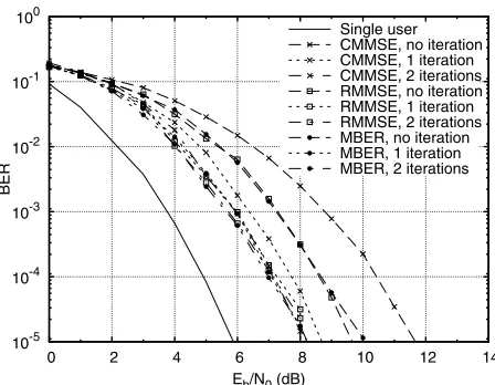
Fig. 3. BER comparison of the CMMSE, RMMSE and MBER iterative beamforming receivers for the BPSK system supporting K = 2 users employing a two-element array
In Fig. 3, only the first two users are activated and the single-user performance is also included as a reference. It can be seen that after two iterations, the CMMSE, RMMSE and MBER algorithms exhibit an iteration gain of3.5dB,1.3dB and1.9dB, respectively, at a BER of10−5. At the same time, the MBER receiver’s performance
is almost the same as that of the CMMSE and RMMSE solutions. The achievable performance gain is modest in this two-user scenario, since the performance is already relatively close to the single-user bound and no further iteration gains are attained for more iterations. This limited iteration gain is the consequence of the limited extrinsic information associated with a simple 2-user scenario.
To elaborate a little further, Fig. 4 shows the attainable perfor-mance, when the number of users is increased to six. It can be seen that the performance of both the MBER and the RMMSE beamforming receivers has significantly improved after six iterations. However, the CMMSE solution is no longer able to provide the desired user seperation, resulting in a high BER floor. It is also seen that in this ‘overloaded’ system supporting three times the number of users in comparison to the number of antennas, the MBER algorithm has the lowest residual BER. After six iterations, the MBER receiver has1.2dB gain over the RMMSE solution at a BER of10−4.
It should also be mentioned that in all simulations discussed above, the angular locations of the users were selected to render the user’s BERs similar. If some of the users exhibit a high BER, this would impose an error propagation phenomenon, potentially limiting the achievable multiuser performance.
V. CONCLUSION
In this paper, we introduced a new iterative MBER soft interference cancellation beamforming receiver, which directly minimizes the BER instead of the MSE. The RMMSE algorithm designed for BPSK was also considered, which minimizes the MSE between the real-valued desired signal and the real part of the complex-valued beamformer output. Our simulations have shown that the MBER solution outperforms both the conventional CMMSE and the RMMSE iterative receivers. Our future research will consider similar wideband scenarios and more sophisticated channel codecs.
10-5 10-4 10-3 10-2 10-1 100
0 2 4 6 8 10 12 14
BER
Eb/N0 (dB) Single user
[image:5.595.329.556.68.239.2]CMMSE, no iteration CMMSE, 2 iterations CMMSE, 6 iterations RMMSE, no iteration RMMSE, 2 iterations RMMSE, 6 iterations MBER, no iteration MBER, 2 iterations MBER, 6 iterations
Fig. 4. BER comparison of the CMMSE, RMMSE and MBER iterative beamforming receivers for the BPSK system supporting K = 6 users employing a two-element array
REFERENCES
[1] J. S. Blogh and L. Hanzo, Third Generation Systems and Intelligent Wireless Networking - Smart Anttenas and Adaptive Modulation. Chich-ester. John Wiley and IEEE Press, 2002
[2] L. Hanzo, M. M¨unster, B. J. Choi, and T. Keller,OFDM and MC-CDMA for Broadband Multi-user Communications, WLANs and Broadcasting. John Wiley and IEEE Press, 2003
[3] C. Berrou, A. Glavieux, and P. Thitimajshima, “Near Shannon limit error correcting coding and decoding: Turbo codes,” inProc. IEEE Int. Conf. Commun., Vol.2, Geneva, Switzerland, pp.1064-1070, May 1993 [4] L. Hanzo, T. H. Liew, and B. L. Yeap,Turbo Coding, Turbo Equalisation
and Space-Time Coding for Transmission over Fading Channels.John Wiley and IEEE Press, 2002
[5] L. Hanzo, C. H. Wong, and M. S. Yee,Adaptive Wireless Transceivers: Turbo-Coded, Turbo-Equalised and Space-Time Coded TDMA, CDMA and OFDM Systems.John Wiley and IEEE Press, 2002
[6] L. Hanzo, L. L. Yang, E. L. Kuan, and K. Yen,Single- and Multi-Carrier DS-CDMA: Multi-User Detection, Space-Time Spreading, Synchronisa-tion, Standards and Networking.John Wiley and IEEE Press, 2003 [7] X. Wang and H. V. Poor, “Iterative (Turbo) soft interference cancellation
and decoding for coded CDMA,”IEEE Trans. Commun., Vol.47, No.7, pp.1046-1060, July 1999
[8] M. T¨uchler, A. C. Singer, and R. Koetter, “Minimum mean squared error equalization usinga prioriinformation,”IEEE Trans. Signal Processing, Vol.50, No.3, pp.673-6820, March 2002
[9] A. Tarable, G. Montorsi, and S. Benedetto, “A linear front end for iterative soft interference cancellation and decoding in coded CDMA,” IEEE Trans. Wireless Communications, Vol.4, No.2, pp.507-518, March 2005
[10] R. Schober, W. H. Gerstacker, and L. Lampe, “On suboptimum receivers for DS-CDMA with BPSK modulation,” Signal Processing, Vol.85, No.6, pp.1149-1163, June 2005
[11] S. Chen, N. N. Ahmad, and L. Hanzo, “Adaptive minimum bit error rate beamforming,”IEEE Trans. Wireless Communications, Vol.4, No.2, pp.341-348, March 2005
[12] A. Wolfgang, N. N. Ahmad, S. Chen, and L. Hanzo, “Genetic algorithm assisted minimum bit error rate beamforming,” in Proc. VTC2004-Spring, pp.142-146, Milan, Italy
[13] M. Y. Alias, A. K. Samingan, S. Chen, and L. Hanzo, “Multiple antenna aided OFDM employing minimum bit error rate multiuser detection,” IEE Electronics Letter, Vol.39, No.24, pp.1769-1770, November 2003 [14] H. V. Poor and S. Verd´u, “Probability of error in MMSE multiuser