Wirel. Commun. Mob. Comput.2005;5:45–56
Published online in Wiley InterScience (www.interscience.wiley.com). DOI: 10.1002/wcm.277
Performance evaluation of distributed-antenna
communications systems using beam-hopping
Honglin Hu1*,y, Jinkang Zhu1and Lie-Liang Yang2
1Department of Electronic Engineering and Information Science, University of Science and Technology of China,
Hefei, Anhui, 230027, P.R. China 2
Department of Electronics and Computer Science, University of Southampton, Southampton SO17 1BJ, U.K.
Summary
Digital beamforming (DBF) techniques are capable of improving the performance of communications systems significantly. However, if the transmitted signals are conflicted with strong interference especially in the direction of the transmitted beams, these directional jamming signals will severely degrade the system performance. In order to efficiently mitigate the interference of the directional jammers, in this contribution a beam-hopping (BH) communications scheme is studied. In the BH communications scheme, only one pair of the beams is used for transmission and it hops from one to the next according to an assigned BH pattern. In this contribution, a range of expressions in terms of the average signal to interference plus noise ratio (SINR) performance have been derived, when both the uplink and downlink are considered. The average SINR performance of the BH scheme and that of the conventional single-beam (SB) as well as multiple-beam (MB) assisted beam-processing schemes have been investigated. Our analysis and results show that the BH scheme is capable of efficiently combating the directional jamming, with the aid of utilizing the directional gain of the beams generated by both the transmitter and the receiver. Furthermore, the BH scheme is capable of reducing the intercept probability of the communications. Therefore, the BH scheme is suitable for communications when several distributed antenna arrays are available around a mobile. Copyright#2005 John Wiley & Sons, Ltd.
KEY WORDS: beamforming; beam-hopping; single-beam; multiple-beam; SINR performance; distributed antenna
1. Introduction
Digital beamforming (DBF) techniques are capable of significantly improving the performance of wire-less communications systems by efficiently making use of the directionality of the beams at the transmit-ter or/and at the receiver [1–4]. In conventional beamforming assisted systems, signals are usually
transmitted using the schemes, which form single-beam (SB) or multiple-single-beams (MB). Furthermore, the beams in the conventional beamforming systems are transmitted in the nearly fixed directions [5,6]. In this case, however if there is a strong interference in the same direction of a transmitted beam, the interference will also be amplified by the beamforming processing operation at the receiver in order to amplify the
*Correspondence to: Honglin Hu, Department of Electronic Engineering and Information Science, University of Science and Technology of China, Hefei, Anhui, 230027, P.R. China.
yE-mail: [email protected]
desired signals. Consequently, the communications system’s performance might be degraded severely and sometimes the communication might even have to be terminated, as the result of the directional jamming. The above-mentioned case may happen in electronic warfare, when the communications are direction-based and when the jamming signals are also directional.
In the field of beamforming, two typical anti-jam-ming techniques have been investigated in the litera-ture, namely antenna-nulling [7–9] and interference cancellation [10–12]. The principles behind the an-tenna-nulling beamforming schemes are that a null is created in the direction of each of the interfering signals, so that the interference from the interfering signals can be efficiently suppressed when amplifying the desired signals. By contrast, when using interfer-ence cancellation, because the interferinterfer-ence signals often have certain properties different from those of the desired signal, they could be eliminated by a specific processing method. The results of References [7–9] have shown that the antenna-nulling schemes are highly effective, if the desired signals and the interfering signals are from different directions. How-ever, if both the desired signals and the interfering signals are from the same or nearly the same direc-tions, i.e. their directions are highly correlated, then the interference from the interfering signals cannot be effectively mitigated by using the antenna-nulling based beamforming schemes. In the context of the interference cancellation based beamforming schemes, it is well recognized that most of them consist of attractive anti-interference techniques in various situations. However, the beamforming schemes using the interference cancellation demand high-complexity signal processing and hence it is relatively hard to achieve real-time communications.
Some of the proposed beamforming schemes use both the antenna-nulling and the interference cancel-lation techniques, in order to mitigate interference. In Reference [13] Kohno has combined the antenna-nulling with the interference cancellation techniques, in order to suppress the co-channel interference in a direct-sequence spread-spectrum multiple-access (SSMA) system. In Reference [14] Eken has com-bined the antenna-nulling techniques with frequency-hopping for combating the following jammers. In these combination schemes a beamformer is first employed at the front stage creating nulls in the directions of the interfering signals, which have direc-tion-of-arrival (DOA) angles different from that of the desired signals. After the nulling operation, an
inter-ference canceller is then employed for further sup-pressing the retaining interfering signals, which have the DOA angles similar to that of the desired signals. The analysis and results in References [13,14] show that these combination schemes constitute a class of attractive interference suppression schemes that are capable of efficiently mitigating the effects of the interfering signals without regarding their DOA angles.
In this contribution, we investigate a novel beam-processing scheme, namely the beam-hopping (BH) communications scheme. In the BH communications scheme, the transmission beams of the transmitter and receiver hop synchronously among a group of preset beams, according to an assigned pattern. Our study and results show that the BH communications scheme constitutes a promising beam-processing scheme, when there exist strong directional interfering signals. In this case, the BH scheme outperforms the conven-tional SB scheme and the MB scheme.
The rest of the contribution is organized as follows: the BH communications scheme is introduced in Section 2, where the conventional SB communica-tions scheme as well as the MB communicacommunica-tions scheme is also outlined. Section 3 provides an analysis of the average signal to interference plus noise ratio (SINR) performance associated with the above men-tioned three types of beam-processing communica-tions schemes. Our numerical results are provided in Section 4, and finally in Section 5 we present our conclusions.
2. Beam-Hopping Assisted Beam-Processing Scheme
Since there areMdistributed DBF arrays located at the outer edge of a cell, the transmission can be configured using various schemes. In this contribution three types of beam-processing schemes are consid-ered in our forthcoming discourse, namely the single-beam (SB) processing scheme, the multiple-single-beam (MB) processing scheme and the beam-hopping (BH) based beam-processing scheme. Let us now describe these beam-processing schemes in detail.
2.1. Single-Beam Scheme
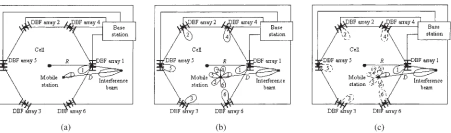
In the conventional SB scheme, the mobile station (MS) in a cell selects only one of the DBF arrays, for example DBF array 1 as shown in Figure 1(a), to communicate with the BS using certain criteria such as maximal received signal power. Therefore, as shown in Figure 1(a), in the conventional SB scheme, the MS forms one beam pointing at the selected DBF array 1. At the same time, the BS sets up one beam pointing at the MS using the selected DBF array 1. According to the above mentioned configurations, we can readily know that in the conventional SB scheme, if there exists a strong interfering signal, emerges in the direction of the beam transmitted from the MS to the selected DBF array 1 or vice versa; the received signal will conflict severe inter-ference that results in significant degradation of the system performance.
2.2. Multiple-Beam Scheme
In the context of the MB scheme, an MS needs to configure M sets of weights. Each of the M sets controls a direction, which points to one of the M
DBF arrays. Therefore, in the MB scheme an MS formsMnumber of beams pointing atM directions. Meanwhile, the BS in the MB scheme forms M beams, one from each of theM DBF arrays, which are pointed at the desired MS. The above-mentioned tasks can be implemented with the aid of the DBF techniques. However, when the MSs position changes, both the MS and the BS have to adapt their weights, in order to retain the beam tracking. Note that, the beam tracking can be achieved with the aid of pilot signals using, for example the adaptive filtering based algorithms [17].
[image:3.569.58.509.53.186.2]In the MB scheme switched-beam assisted beam-processing schemes are widely used, which switch the transmission beam to the next after transmission for a given duration of time using a beam [18]. When using switched-beam assisted beam-processing, however the probability of an incorrect beam selection is likely to be high, when there is a strong interference in the direction of the transmission. This is the case, even when the decision variable for the desired signal is the output of a matched-filter. This is because the decision variable is constituted by the total received signal strength of (SþIþN) instead of the desired signal strengthS alone. Readers interested in the details of this issue are referred to Reference [19], where both the probability of incorrect beam selection and the impact of the incorrect beam selection on the system performance have been analyzed. In this contribution, since we assume that the DBF arrays are distributed at the outer edges of a cell, an alternative but practical beam-processing scheme can be employed. In this alternative beam-processing scheme, the transmission always uses all theMnumber of beams, as shown in Figure 1(b). TheMnumber of signals received by the
MS or the BS are then combined using the combining scheme, such as maximal ratio combining (MRC), equal gain combining (EGC) or selection combining (SC) etc.
2.3. Beam-Hopping Scheme
In the BH scheme, the BS configures M sets of weights to form M beams, one from each of the M DBF arrays and pointing at the desired MS. Mean-while, the MS also configures M sets of weights to formMbeams pointing atMDBF arrays respectively. By the pilot-aided DBF techniques, the above-men-tioned tasks can be implemented, which is similar to the MB scheme case. Furthermore, when the MS moves in the cell, both the MS and the BS adapt their weights to retain the beam tracking.
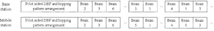
After both the MS and the BS have establishedM beams, which point at each other accordingly, the BS coordinates a pseudo random BH pattern with the MS with the aid of signaling. Here the BH pattern is a list containing beams of operation in the specific order of hopping, and the BH pattern is known by both the BS and the MS. According to the BH pattern, the BS hops the transmitted beam among theM DBF arrays at a determinate hopping rate. At the same time, in order to synchronize with the BSs transmission, the MS also hops its beams at the same hop rate as the BS, according to the same BH pattern of the BS, as shown in Figure 1(c). Figure 2 shows a possible BH arrange-ment, where the transmission beams are activated from one to another after certain time duration. More specifically, in the first stage, the BS and the MS formMbeams pointing at each other respectively with the aid of the pilot signal. After that, the BH pattern is arranged and the transmission beams will hop in the sequence of beam 2, beam 3, beam 6 and so on. Therefore, in the BH scheme only one pair of the beams is activated for the transmission at one time. Once the BH pattern is determined, the transmission beams of both the MS and the BS will hop synchro-nously according to the BH pattern. Hence, the BH scheme does not require a complex beam-switching
strategy, which has to be employed by the switched-beam assisted switched-beam-processing schemes.
The BH assisted beam-processing scheme has a range of advantages. First, compared to the SB assisted beam-processing scheme, the BH based beam-processing scheme is able to efficiently mitigate the directional jamming, since the activated transmis-sion beam in the BH scheme is continuously hopping. Hence, both a high beam gain and a low intercept probability of communications can be achieved in the BH scheme. Second, compared to the MB assisted beam-processing scheme, the interception probability in the BH scheme may be much lower, than that in the MB scheme. The low-interception is achieved, since at one time only single pair of beams is activated for transmission in the BH scheme. Furthermore, in the BH scheme the neighboring mobile stations can be assigned with orthogonal hopping patterns, and they can access the network using the spatial multiple-access schemes with the aid of the assigned orthogo-nal hopping patterns. Hence, the BH based system can be expected to provide a higher system capacity, than the MB based system. Based on the above observa-tions and the results provided in Section 4, it can be shown that the BH assisted beam-processing scheme constitutes a promising scheme, especially in military communications.
In the BH assisted beam-processing scheme either slow beam-hopping (SBH) or fast beam-hopping (FBH) can be employed. In the SBH systems, the BH dwell-time Th is higher than the data symbol
durationT. In other words, in the context of the SBH scheme several data symbols are transmitted within one BH dwell-time. In contrast to the SBH scheme, in the FBH systems, the BH dwell-timeThis lower
[image:4.569.107.469.601.654.2]than the data symbol duration T, and one data symbol is transmitted using several BH hops. In comparison with the SBH scheme, the FBH scheme has a higher complexity. However, by using the FBH scheme the received signal can be provided with spatial diversity and, hence the system’s performance can be efficiently improved by com-bining the spatially independent replicas with the
aid of some optimum or sub-optimum combining schemes [20].
Above, we have described three types of beam-processing schemes, namely the SB, MB and BH schemes. Let us now derive the average SINR asso-ciated with these beam-processing schemes in the next section.
3. Average SINR Performance Analysis
In this section, we derive the average SINR expres-sions for the SB, MB and BH schemes. In our analysis, we assume that there is a strong interfering signal pointing at the desired MS. For the sake of simplicity, we assume that there exists no co-channel interference and no multipath fading. Furthermore, we assume that the beams of the MS and the DBF arrays precisely point at each other respectively. In the context of the BH scheme, the average SINR is derived under the assumption of using SBH, i.e. by assuming that several data symbols are transmitted within one BH dwell-time.
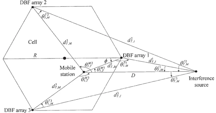
We take a three DBF arrays cell (M¼3), for example as illustrated in Figure 3. The cell radius isR, the distance from the interference source to the MS isD, the angle formed from the cell center and the MS to the DBF array 1 is .TiI;M,Ii
T;Mand
Mi I;T
(i¼1;2;. . .;M) denote the angle formed from the interference source and the MS to the DBF arrayi, the angle formed from the DBF arrayiand the MS
to the interference source, and the angle formed from the interference source and the DBF arrayito the MS respectively.di
T;Mand d i
T;I (i¼1;2;. . .;M)
denote the distance from the DBF array i to the MS, and the distance from the DBF array i to the interference source respectively. The sub-script or supersub-script T, I and M refer to the DBF array, the interference source and the MS respectively.
3.1. Downlink Performance
3.1.1. Average SINR of the BH scheme
In the context of the BH scheme, we assume that random BH patterns are employed and that each of the MDBF arrays is activated at the same probability for transmitting information with the MS. Consequently, the average SINR of the BH scheme can be expressed as
SINRdBH¼10log 1 M
XM
i¼1
10Pd Si=10
10PdJi=10
!
¼10log 1 M
XM
i¼1
10 PdSiPdJi ð Þ
10
! ð1Þ
where the superscript d is the indication of downlink, Pd
SiandPdJirepresent the desire signal’s power and the
[image:5.569.97.465.467.659.2]interference plus noise power respectively, received by the ith beam of the MS. For convenience, these power-related variables are expressed in the form of
decibel (dB) values. Furthermore, in the following all the power-related variables are in the form of dB values, unless specifically indicated. In Equation (1), the power received from the desired signal can be expressed as
PdSi¼PTþGTð0Þ þGMð0Þ PL dTi;M
ð2Þ
while the power due to the interfering signal and the background noise can be expressed as
PdJi¼PIþGIð0Þ þGM MiI;T
PLðDÞ þN0 ð3Þ
In Equations (2) and (3), PT and PI represent the
transmitted power of an activated DBF array and the interfering signal respectively, GTðÞ; GMðÞ and
GIðÞ denote the beam gain functions of the DBF
array, the MS and the interfering signal respectively, when the incident angle is . The path loss for a transmitter-to-receiver (T-R) distance of l is ex-pressed asPL(l) in Equations (2) and (3). Finally, in Equation (3)N0denotes the single-sided power
spec-tral density of the additive white Gaussian noise (AWGN).
3.1.2. Average SINR of the SB scheme
For the SB assisted beam-processing communications scheme, since only a fixed DBF array, for example the DBF array 1, transmits information to the MS, the average SINR can be expressed as
SINRdSB¼PdS1PdJ1¼ PTþGTð0ÞþGMð0ÞPL dT1;M
PIþGIð0ÞþGM MI;T1
PLðDÞN0
ð4Þ
where the variables have the same meaning, as the corresponding variables in Equations (2) and (3).
3.1.3. Average SINR of the SB scheme
Finally, in the context of the MB scheme, since it uses all theMbeams, each of the DBF arrays contributes one; to communicate with the MS, the transmitted power from each DBF array should be PT10logM dB, in order to retain a given total of
transmitted power ofPT. Assuming that a combining
scheme is employed by the MS in order to combine the signals from theMDBF arrays, the average SINR then can be expressed as [21]
SINRdMB ¼10log 1 2
XM
i¼1
wi
ffiffiffiffiffiffiffiffiffiffiffiffiffiffiffiffiffiffiffiffiffiffiffiffiffiffiffi
210 Pd
Si10logM
10
q !2
2 4 3 5 10log X M
i¼1
w2i 10 Pd
Ji
10
!
¼20log X
M
i¼1
wi
ffiffiffiffiffiffiffiffiffiffiffiffiffiffiffiffiffiffiffi
10 PdSi10logM
10
q !
10log X
M
i¼1
w2i 10 Pd
Ji
10
!
ð5Þ
where wi represents the combining weight
corre-sponding to the signal received by the ith beam of the MS. Specifically, when the EGC scheme is as-sumed, then we have wi¼1 for i¼1;2;. . .;M.
Consequently, Equation (5) can be simplified as
SINRdMB EGC¼20log X
M
i¼1
ffiffiffiffiffiffiffiffiffiffiffiffiffiffiffiffiffiffiffi
10 Pd
Si10logM
10
q !
10log X
M
i¼1
10 Pd
Ji
10
! ð6Þ
By contrast, when the MRC scheme is employed, then
we have wi¼10
Pd
Si10logM2PdJi
20 for i¼1;2;. . .;M.
Hence, we have
SINRdMB MRC¼10log X
M
i¼1
10
PdSi10logMPdJi
10 !
¼10log 1 M
XM
i¼1
10 Pd
SiPdJi
10
! ð7Þ
By comparing Equation (1) with Equation (7) it can be shown that, with the aid of the MRC, the MB assisted beam-processing scheme is capable of achieving the same average SINR, as the BH assisted beam-processing scheme, i.e. we have
SINRdMB MRC¼SINRdBH.
selected as the decision variable. Hence, the average SINR can be expressed as
SINRdMB SC¼maxPdSi10logMPdJi; for i¼1;2;. . .;Mg ð8Þ
3.2. Uplink Performance
The average SINR expressions for the uplink asso-ciated with the three beam-processing schemes can be derived using similar approaches as that for the down-link. However, in contrast to Equations (2) and (3), the received power Pu
Si from the desired signal and
the power Pu
Ji from the interfering signal and noise
by theith DBF array must be expressed as
PuSi¼PMþGMð0Þ þGTð0Þ PL dTi;M
ð9Þ
and
PuJi¼PIþGI IiT;M
þGT TiI;M
PL diT;I
þN0
ð10Þ
where the superscript u is for indicating the uplink,PM
represents the transmitted power by one of the M beams of the MS, while the details of the other variables are referred to the explanations associated with Equations (2) and (3). With the aid of Equations (9) and (10), the average uplink SINR expressions corresponding to the three types of beam-processing schemes concerned can be readily summarized using similar approaches as those for the downlink.
In this section, the average SINR expressions in the context of the beam-processing schemes using SB, MB and BH have been derived, when both uplink and downlink are considered respectively. In the next section a range of numerical results are provided and discussed for comparison among these beam-processing schemes.
4. Numerical Results
In this section, we compare the average SINR perfor-mance of the beam-processing schemes using SB, MB and BH, as discussed in the previous sections. Note that in the BH scheme, we assume that random BH patterns are employed and that each of the M DBF arrays is activated at the same probability for
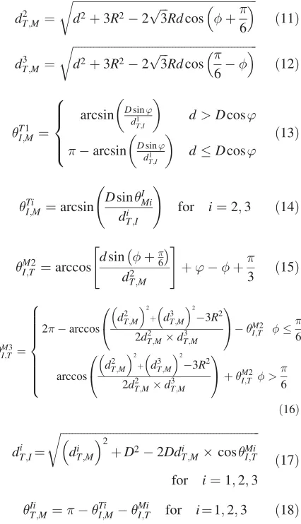
[image:7.569.297.510.190.561.2]transmitting information with the MS. Our numerical results are evaluated based on two typical cell config-urations. The first cell configuration is shown in Figure 3, where M¼3 DBF arrays are employed. The second cell configuration example is shown in Figure 1, where theM¼6 DBF arrays are located at the six corners of the hexagon. Let M1
I;T ¼’ and
d1
T;M¼d, then the geometric related parameters for
the cell using three DBF arrays can be summarized as follows:
d2T;M¼
ffiffiffiffiffiffiffiffiffiffiffiffiffiffiffiffiffiffiffiffiffiffiffiffiffiffiffiffiffiffiffiffiffiffiffiffiffiffiffiffiffiffiffiffiffiffiffiffiffiffiffiffiffiffiffiffiffiffiffiffiffiffiffi
d2þ3R22pffiffiffi3Rdcos þ
6
r
ð11Þ
d3T;M¼
ffiffiffiffiffiffiffiffiffiffiffiffiffiffiffiffiffiffiffiffiffiffiffiffiffiffiffiffiffiffiffiffiffiffiffiffiffiffiffiffiffiffiffiffiffiffiffiffiffiffiffiffiffiffiffiffiffiffiffiffiffiffiffi
d2þ3R22pffiffiffi3Rdcos
6
r
ð12Þ
T1 I;M¼
arcsin Ddsin1 ’
T;I
d>Dcos’
arcsin Ddsin1 ’
T;I
dDcos’
8 > > < > > : ð13Þ Ti
I;M¼arcsin
DsinIMi di
T;I !
for i¼2;3 ð14Þ
M2
I;T ¼arccos
dsinþ6 dT2;M
" #
þ’þ 3 ð15Þ
M3 I;T¼
2arccos
d2 T;M 2
þ d3
T;M 2
3R2
2dT2;Md3T;M
0 @
1 AM2
I;T
6
arccos d2T;M
2
þ d3T;M
2 3R2
2d2T;MdT3;M
0 @
1 AþM2
I;T >
6 8 > > > > > > > < > > > > > > > :
ð16Þ
diT;I¼
ffiffiffiffiffiffiffiffiffiffiffiffiffiffiffiffiffiffiffiffiffiffiffiffiffiffiffiffiffiffiffiffiffiffiffiffiffiffiffiffiffiffiffiffiffiffiffiffiffiffiffiffiffiffiffiffiffiffiffiffiffiffiffiffiffiffiffiffi
di T;M
2
þD22Ddi
T;McosMiI;T r
for i¼1;2;3 ð17Þ
Ii
T;M¼
Ti
I;M
Mi
I;T for i¼1;2;3 ð18Þ
Note that the geometric related parameters for the DBF array 1, DBF array 2 and DBF array 3 are the same for the cells using three DBF arrays and six DBF arrays, as illustrated in Figures 3 and 1. The other geometric related parameters for the cell using six DBF arrays can be summarized as follows:
dT4;M¼
ffiffiffiffiffiffiffiffiffiffiffiffiffiffiffiffiffiffiffiffiffiffiffiffiffiffiffiffiffiffiffiffiffiffiffiffiffiffiffiffiffiffiffiffiffiffiffiffiffiffiffiffiffiffi
d2þR22Rdcos þ
3
r
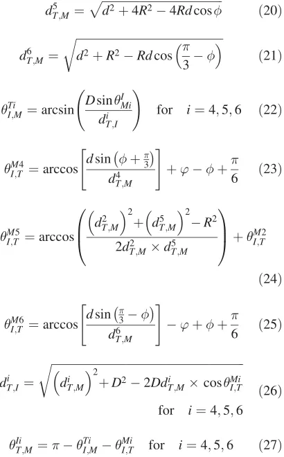
dT5;M¼pffiffiffiffiffiffiffiffiffiffiffiffiffiffiffiffiffiffiffiffiffiffiffiffiffiffiffiffiffiffiffiffiffiffiffiffiffiffiffiffiffiffid2þ4R24Rdcos ð20Þ
d6T;M ¼
ffiffiffiffiffiffiffiffiffiffiffiffiffiffiffiffiffiffiffiffiffiffiffiffiffiffiffiffiffiffiffiffiffiffiffiffiffiffiffiffiffiffiffiffiffiffiffiffiffiffiffi
d2þR2Rdcos
3
r
ð21Þ
Ti
I;M¼arcsin
DsinIMi di
T;I !
for i¼4;5;6 ð22Þ
M4
I;T ¼arccos
dsinþ3 d4
T;M
" #
þ’þ 6 ð23Þ
M5
I;T ¼arccos
dT2;M
2
þ d5T;M
2
R2 2d2
T;MdT5;M 0
B @
1 C
AþM2
I;T
ð24Þ
M6
I;T ¼arccos
dsin3 d6
T;M
" #
’þþ 6 ð25Þ
dTi;I ¼
ffiffiffiffiffiffiffiffiffiffiffiffiffiffiffiffiffiffiffiffiffiffiffiffiffiffiffiffiffiffiffiffiffiffiffiffiffiffiffiffiffiffiffiffiffiffiffiffiffiffiffiffiffiffiffiffiffiffiffiffiffiffiffiffiffiffiffi
di T;M
2
þD22Ddi
T;McosMiI;T r
for i¼4;5;6 ð26Þ
Ii
T;M¼
Ti
I;M
Mi
I;T for i¼4;5;6 ð27Þ
Assuming that the path loss obeys the log-distance path loss model [16], then the path loss can be written as
PLðlÞðdBÞ ¼PLðl0Þ þ10nlog
l l0
þX ð28Þ
when the distance between the transmitter and the receiver is l. In Equation (28)l0 represents the
so-called closed-in reference distance, which is a known received power reference point. n is the path loss exponent and finally, X represents a zero-mean Gaussian distributed random variable having a standard deviation expressed in the form of dB. Furthermore, in our numerical evalua-tion, we assume that the beam gain functions with respect to the DBF arrays, the mobile station (MS) as well as the interfering signal can all be expressed as [22]
GðÞðdBiÞ ¼ Csin 2 wþ1
2w
C >2w
(
ð29Þ
whereis the incident DOA angle. If, then we have 2. Furthermore, in Equation (29)Cis a gain coefficient and w is the half beamwidth, as
illustrated in Figure 4. Note that, the beam pattern issue is beyond the scope of this paper, hence the details are not considered furthermore in our forth-coming discourse.
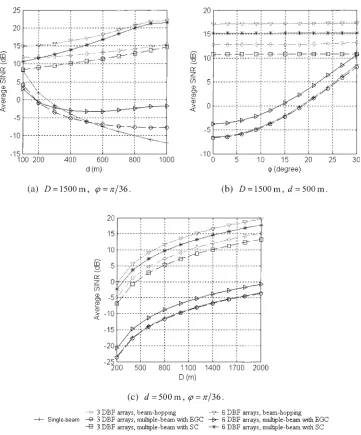
In Figures 5 and 6, we demonstrate the downlink and uplink performance comparisons among the three types of beam-processing schemes, namely among the SB, MB and BH schemes respectively. The perfor-mance curves were drawn with respect to various values of d,’and Dfor both the cell using M¼3 DBF arrays and the cell using M¼6 DBF arrays. Since the average SINR performance of the BH scheme and the MB scheme using MRC are the same, as illustrated in Equation (7), the average SINR curves corresponding to the MB scheme using the MRC were not distinguished in the figures.
The rest parameters used in Figures 5 and 6 are as follows. The half beamwidths of GTðÞ;GMðÞ
and GIðÞ were set to be =6. Under these
conditions, the gain coefficients were computed as CT ¼20;CM¼15 and CI ¼30 respectively.
More-over, we had R¼1000 m; ¼=4;PT ¼30 dBm;
PM¼23 dBm;PI ¼30 dBm; N0¼6 dB;l0¼100 m;
¼10 dB;PLðl0Þ ¼70 dB andn¼2.
[image:8.569.71.276.57.387.2]Figure 5(a) is drawn against the distancedbetween the MS and the DBF array 1, Figure 5(b) is evaluated versus the angle’as shown in Figure 3, and finally in Figure 5(c), we show the effect of the distance D, between the MS and the interference source, on the average SINR performance. From Figure 5 corre-sponding to the downlink, we observe that the average SINR achieved by either the BH scheme or the MB scheme using SC is significantly higher, than that achieved by the SB scheme, when there is a strong directional interference. However, the downlink SINR performance of the MB scheme using the EGC is improved insignificantly, comparing with the SB
Fig. 4. Beam pattern of the DBF arrays, the mobile station (MS) and the interfering signal, whereis the incident DOA
scheme. This is because, when using EGC, one of the combined beams by the MS is always severely inter-fered by the strong interfering signal and the com-bined signal always contains the whole power from the interfering signal. Consequently, when using EGC, the average SINR achieved by the MB scheme is low. Furthermore, according to Figure 5(a), (b), (c), the BH scheme and the MB scheme using MRC outperform all the other types of beam-processing schemes and achieve the highest average SINR value.
[image:9.569.102.463.50.485.2]Note again that, according to our analysis carried out in the previous Section 4, both the BH scheme and the MB scheme using MRC achieve the same average SINR performance. Furthermore, Figure 5(a), (b), (c) show that the average SINR performance usingM¼6 DBF arrays is generally better than that usingM¼3 DBF arrays. This phenomenon can be readily under-stood, since with a higher number of beams, the probability of hit due to the interfering signal in the BH scheme is lower. In the context of the MB scheme,
Fig. 5. Downlink average SINR performance for the three types of beam-processing schemes, namely the SB, MB and BH schemes, when a cell using either three DBF arrays or six DBF arrays are assumed. In Figure 5(a),drepresents the distance between the MS and the DBF array 1, in Figure 5(b),’is the angle between the line connecting the MS and the DBF array 1 and the line connecting the MS and the interference source, finally, in Figure 5(c),Drepresents the distance between the MS and the
a higher number of beams imply a higher number of diversity components, which also results in improved performance, when the MRC or SC is employed for combining the diversity components.
More specifically, as shown in Figure 5(a), the downlink SINR performance for the SB scheme degrades rapidly, when increasing the distance d between the transmitter and the receiver. This is the result of the path loss, which makes the received power by the DBF array 1 from the desired signal
[image:10.569.100.468.52.471.2]become weak, when increasing the distance d. In contrast to the SB scheme, the downlink SINR per-formances for both the BH scheme and the MB scheme using SC improve slightly, when the distances from the MS to most of the DBF arrays become shorter. From Figure 5(b), we observe that the average SINR performance of the SB scheme becomes worse, when decreasing the value of ’, i.e. as shown in Figure 3, when the interference source moves close to the direct path between MS and DBF array 1. In
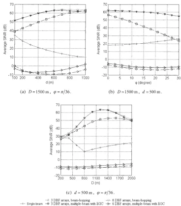
Fig. 6. Uplink average SINR performance for the three types of beam-processing schemes, namely the SB, MB and BH schemes, when a cell using either three DBF arrays or six DBF arrays are assumed. In Figure 6(a),drepresents the distance between the MS and the DBF array 1, in Figure 6(b),’is the angle between the line connecting the MS and the DBF array 1 and the line connecting the MS and the interference source, finally, in Figure 6(c),Drepresents the distance between the MS and the
[image:10.569.293.468.56.225.2]Figure 5(c) the downlink average SINR is evaluated versus the distance between MS and the interference source. As expected, the average SINR performance improves, when increasing the value D. From Figure 5, we could also observe that the performance of BH scheme outperforms that of MB scheme, because for the BH scheme, since it only uses one beam at one time to communicate, the transmitted power of one beam is larger than that of the MB scheme.
In Figure 6(a), (b), (c), we demonstrate the uplink average SINR performance. As in Figures 5, 6(a) is drawn against the distance d between MS and DBF array 1, Figure 6(b) is evaluated versus the angle’, as shown in Figure 3, and finally, in Figure 6(c) we show the effect of the distanceD, between the MS and the interference source, on the average SINR performance. Generally speaking, the results of these figures show that both the BH scheme and MB scheme using SC outperform the SB scheme. However, as shown in these figures, there may occur intersects between some curves. The crossovers occur mainly because we assume that the strong interference was directed to MS instead of DBF array 1. Since one of the combined branches in the MB scheme contains a very low SINR value due to the interfering signal, the uplink average SINR performance of the MB scheme using EGC is very poor and, in some cases it is even poorer, than that of the SB scheme, as shown in Figure 6(a), (b), (c). Furthermore, because the SINR of the poorest com-bined branch changes irregularly in response to the variation of the parameters, the uplink average SINR of the MB scheme using EGC varies in a wave-like manner. This phenomenon becomes explicit in the case, when each cell uses six DBF arrays. Similar to Figure 5, the results in Figure 6 show that the uplink average SINR performance of the cell using six DBF arrays, in most cases, is superior to that of the cell using three DBF arrays. From Figure 6(b), we also observe that SB scheme, BH scheme and MB scheme with SC have nearly the same performance when’¼=6, this is because we assumed that the half beamwidthw is
=6. When’¼=6, the signal received by the DBF array 1 becomes the strongest in the cell with three DBF arrays. In addition, in Figure 6(c), we could see that the curves wave irregularly, this is because whenD increases, the strong interference source first becomes closer to the DBF array 1 and then moves further away from all the DBF arrays. Also, note that when the position of the strong interference source changes, the other parameters, such as the distance from the inter-ference to the DBF arrays and the incident angles of the interference change accordingly.
5. Conclusions
In this contribution, a novel beam-processing scheme, namely BH scheme, has been studied. The average SINR performance of the BH scheme and that of the conventional SB as well as MB assisted beam-proces-sing schemes have also been investigated. A range of expressions in terms of the average SINR performance have been derived, when both the uplink and downlink are considered. With the aid of the derived expressions, we have presented a range of numerical results in the context of the beam-processing schemes considered. From our analysis and numerical results, we can con-clude that the BH scheme is capable of combating strong directional interference. It significantly outper-forms the SB assisted beam-processing scheme. It is also capable of achieving better performance than MB assisted beam-processing using both EGC and SC based beam-combining schemes. Both the BH scheme and the MB scheme using the MRC based beam-combining achieve the same average SINR performance. There-fore, BH scheme constitutes one of the promising schemes, which are suitable for the communications systems employing distributed antenna arrays.
References
1. Kohno R. Spatial and temporal communication theory using adaptive antenna array.IEEE Personal Communications1998; 5(1): 28–35.
2. Chiba I, Miura R, Tanaka T, Karasawa Y. Digital beam forming (DBF) antenna system for mobile communications. IEEE Aerospace Electronic System Magazine1997;12(9): 31–41. 3. Miura R, Tanaka T, Horie A, Karasawa Y. A DBF self-beam
steering array antenna for mobile satellite applications using beam-space maximal-ratio combination.IEEE Transactions on Vehicular Technology1999;48(3): 665–675.
4. Kai-Bor Y, Murrow DJ. Adaptive digital beamforming for angle estimation in jamming.IEEE Transactions on Aerospace Electronic System2001;37(2): 508–523.
5. Kwala P, Sheikh AUH. Adaptive multiple-beam array for wireless communications,ICAP’93, Vol. 2, Edinburgh, UK, April 1993; pp. 971–974.
6. Ahmed MH, Mahmoud SA. Soft capacity analysis of TDMA systems with slow-frequency hopping and multiple-beam smart antennas.IEEE Transactions on Vehicular Technology2002; 51(4): 636–647.
7. Liu Q-G, Zou L-H. A novel beamformer for cancelling jam-mers by exactly nulling,AP-S. Digest, Vol. 2, June 1991; pp. 952–955.
8. Lo T, Litva J. Adaptive beam-space nulling of multipath signals,AP-S. Digest, June 1988;3; pp. 984–987.
9. Nicolaescu I, Losif FD. Null steering arrays. InProceeding of TELSIKS 2001, Vol. 2, Nisˇ Yugoslavia, September 2001; pp. 679–682.
11. Denno S. Maximum likelihood sequence estimation used for multibeam interference cancellation,VTC 2002 Spring, Vol. 2, Birmingham, Alabama, USA, May 2002; 1800–1804. 12. Seijoon S, Sunghun J, Chungyong L. The projection matrix
method for interference cancellation,VTC 2001 Spring, Vol. 3, Rhodes Island, Greece, May 2001; pp. 1563–1567.
13. Kohno R, Imai H, Hatori M, Pasupathy S. Combinations of an adaptive array antenna and a canceller of interference for direct-sequence spread-spectrum multiple-access system. IEEE Journal on Selected Areas in Communications 1990; 8(4): 675–682.
14. Eken F. Use of antenna nulling with frequency-hopping against the follower jammer.IEEE Transactions on Antennas Propa-gation1991;39(9): 1391–1397.
15. Lee WCY. Smaller cells for greater performance.IEEE Com-munications Magazine1991;29(11): 19–23.
16. Rappaport TS.Wireless Communications Principles and Prac-tice, Prentice-Hall, Inc.: Englewood Cliffs, NJ, 1996. 17. Ihara T, Tanaka S, Sawahashi M, Adahi F. Fast antenna-weights
tracking algorithm of adaptive antenna array diversity receiver in W-CDMA reverse link,VTC 2000 Spring, Vol. 2, Tokyo, May 2000; pp. 961–965.
18. Ming-Ju H, Stuber GL, Austin MDR. Performance of switched-beam smart antennas for cellular radio systems. IEEE Transactions on Vehicular Technology 1998; 47(1): 10–19.
19. Matsumoto T, Nishioka S, Hodder DJ. Beam-selection perfor-mance analysis of a switched multibeam antenna system in mobile communications environments.IEEE Transactions on Vehicular Technology1997;46(1): 10–20.
20. Dell’Anna M, Aghvami AHR. Performance of optimum and suboptimum combining at the antenna array of a W-CDMA system.IEEE Journal on Selected Areas in Communications 1999;17(12): 2123–2137.
21. Kavehrad M, McLane PJ. Performance of low-complexity channel coding and diversity for spread spectrum in indoor wireless communication. AT&T Technology Journal 1985; 64(8): 1927–1965.
22. Rodriguez-Osorio RM, Veguillas DM, Ariet LDH, Ramon MC. Switched beam antennas performance evaluation and capacity increase for UMTS systems, SCVT-200, Leuven, Belgium, October 2000; pp. 82–87.
Authors’ Biographies
Honglin Hu received his Ph.D. in Communications and Information Sys-tem from the University of Science and Technology of China, 2004. Currently, he is with Siemens ICM in Munich, Germany. In Siemens, he researches mainly on SDMA and OFDM techni-ques, also on the crossed-layer design and optimization for future wireless communication systems.
Jinkang Zhu is a professor in the Department of Electronic Engineering and Information Science of University of Science and Technology of China (USTC). Now he is the director of Personal Communication Network and Spread Spectrum Laboratory of USTC, chair of the Academic Committee of School of Information Science and Technology of USTC, vice-chair of the Academic Committee of USTC. He was permanent vice-president of School of Information Science and Tech-nology of USTC, chairman of PCN Experts Group of Communication Project of National R & D on High-nology Programme of China, member of Information Tech-nology Expert Group of the Chinese Academy of Sciences, member (Representation of China Mainland) of Technical Forum on Wireless Communications of Asia Pacific Region, member of Technical Advisory Committee of IEEE VTC’99 Fall, member of Technical Program Committee of IEEE VTC’2000 and member of Technical Program Committee of SCI’2001. His research area is wireless and mobile com-munications, CDMA and spread spectrum comcom-munications,
signal process of communications and wireless networks. He got two awards from Ministry of Science and Technol-ogy of China, three awards from Chinese Academy of Science. He published 5 books and 100 papers, where synchronous CDMA method proposed is used in TD-SCDMA standard of 3G as basic technology.