SWITCHING CIRCUIT DESIGN FOR LINEAR BI-STATICS ULTRA WIDEBAND (UWB) ANTENNA IN MICROWAVE BONE IMAGING
APPLICATION
OOI JIAN PING
This Report is Submitted in Partial Fulfillment of Requirements for the Bachelor Degree of Electronic Engineering (Telecommunication Electronics)
with Honours
Fakulti Kejuruteraan Elektronik dan Kejuruteraan Komputer Universiti Teknikal Malaysia Melaka
v
DEDICATION
Special Dedicated to My beloved family,
vi
ACKNOWLEDGEMENT
First and foremost, I would like to express my gratitude to my main supervisor, Dr. Noor Azwan Bin Shairi for his invaluable guidance throughout my final year project. Guidance such as proper method of doing research, technical report writing and technical advice whenever I have problems in project design are truly important to complete my final year project. In addition, I would like to extend my gratitude to my co-supervisor, Dr. Imran Bin Mohd Ibrahim also. Undeniable, his encouragement, suggestion in presentation techniques and project progress monitoring have motivate me in completing this final year project.
I would also like to appreciate the aids given by students doing master research course. They are always able to answer me when I have any questing regarding the uses of simulation software. Besides that, I would like to thank to all my friends as well as my family for their assist and moral support.
vii
ABSTRACT
viii
ABSTRAK
ix
TABLE OF CONTENTS
CHAPTER TITLE PAGES
PROJECT TITLE i
REPORT STATUS VERIFICATION FORM ii
DECLARATION iii
SUPERVIOR’S APPROVAL iv
DEDICATION v
ACKNOWLEDGEMENT vi
ABSTRACT vii
ABSTRAK viii
TABLE OF CONTENTS ix
LIST OF TABLES xii
LIST OF FIGURES xiii
LIST OF ABBREVIATION xvii
LIST OF APPENDICES xviii
I INTRODUCTION
1.1 Project overview 1
1.2 Problem statement 2
1.3 Objectives 3
1.4 Scope of project 3
1.5 Thesis outline 3
II LITERATURE REVIEW
x
2.3 Benefits of ultra wide band antennas 9
2.4 3D imaging abilities 10
2.5 Benefits of RF switches 11
2.6 RF switches 12
2.7 Calibration of microwave imaging systems 12 2.8 Microwave imaging system block diagram 13 2.9 Antenna configuration of microwave imaging
system
14
2.10 Antenna array arrangement 15
2.11 PIN diode switch topology 16
2.12 Isolation improvement of switches 19 2.13 Defected Ground Structure (DGS) 20
III METHODOLOGY
3.1 Project methodology 22
3.2 Components selection 23
3.2.1 Diode selection 23
3.2.2 Capacitor selection 25
3.2.3 Inductor selection 26
3.3 Design process of the switch 26
3.3.1 Ideal SPDT design 29
3.3.2 Non-ideal SPDT design 31
3.3.3 Ideal SP4T design 32
3.3.4 Non-ideal SP4T design 32
3.3.5 Momentum design 33
IV RESULTS AND DISCUSSIONS
xi
4.1.2 Capacitor comparison 43
4.1.3 Inductor comparison 46
4.2 Design results 50
4.2.1 Ideal SPDT design result 51
4.2.2 Non-ideal SPDT design result 56
4.2.3 Ideal SP4T design result 57
4.2.4 Non-ideal SP4T design result 58
4.2.5 Momentum design result 60
V CONCLUSION
5.1 Conclusion 63
5.2 Future work 63
REFERENCES 65
xii
LIST OF TABLES
NO. TITLE PAGES
1.1 Design parameters of SP4T switch 3
2.1 Scanning time comparison 12
2.2 Comparison of simulated and measured isolation between PIN diode switch with DGS and without DGS
21
3.1 Major specification of Rogers RO4350B 31
4.1 Specification of all capacitor model 43
4.2 Specification of all inductor model 47
4.3 Comparison of insertion loss and isolation provided by different diode configuration
xiii
LIST OF FIGURES
NO. TITLE PAGES
1.1 Block diagram of medical bone imaging system 2 2.1 MTI system with 16 monopole antennas positioned in circular
array
6
2.2 Illustration of MTI scan on human heel 6
2.3 Comparison of (a) MTI system result with (b) CT scan result 7 2.4 TSAR imaging system. (a) Damages meniscus tissues. (b)
Imaging results.
8
2.5 Variation in S11 with the changes in bone thickness (dielectric properties changes)
9
2.6 Drops in S11 indicating low bone density or bone crack 9 2.7 Comparison of results of (a) UWB system and (b) 1st
generation Microwave Imaging System
10
2.8 Example of mechanical moved 3D imaging system 11
2.9 RF switched imaging system 11
2.10 Microwave imaging system block diagram 14
2.11 Configuration of (a) mono-static antenna and (b) bi-static antenna
14
2.12 Circular antenna arrangement 15
2.13 Linear antenna arrangement 16
2.14 Series SPST switch 16
2.15 Shunt SPST switch 17
2.16 Series-shunt SPST switch 17
2.17 Single shunt switch 17
2.18 Series-shunt switch 18
2.19 Series-shunt-shunt switch 18
xiv
2.22 Radial stub resonator added to SPDT 19
2.23 Open stub resonator added to SPDT 20
2.24 SPST PIN diode switch with square dumbbell DGS 20
3.1 Project flow chart 23
3.2 Diode series connection test circuit 24
3.3 Diode shunt connection test circuit 25
3.4 Capacitor testing circuit 25
3.5 Inductor testing circuit 26
3.6 Design process flow chart 28
3.7 Series-shunt diode connection 29
3.8 smp1320_079 model 30
3.9 Conventional diode model 30
3.10 Ideal SPDT design A 30
3.11 Ideal SPDT design B 30
3.12 Ideal SPDT design C 31
3.13 LineCalc function in ADS software 32
3.14 Choosing simulation view 34
4.1 Insertion loss of diode ba277 (NXP semiconductor) in series connection (a) biased condition (b) un-biased condition
37
4.2 Insertion loss of diode ba277 (NXP semiconductor) in shunt connection (a) biased condition (b) un-biased condition
38
4.3 Insertion loss of diode bap64_02 (NXP semiconductor) in series connection (a) biased condition (b) un-biased condition
39
4.4 Insertion loss of diode bap64_02 (NXP semiconductor) in shunt connection (a) biased condition (b) un-biased condition
40
4.5 Insertion loss of diode smp1320_079 (Skyworks Solution) in series connection (a) biased condition (b) un-biased condition
41
4.6 Insertion loss of diode smp1320_079 (Skyworks Solution) in shunt connection (a) biased condition (b) un-biased condition
42
4.7 Insertion loss of ideal capacitor 44
xv
4.9 Insertion loss of capacitor model GRM0225C1C9R7CD05 (9.7 pF) from Murata
45
4.10 Insertion loss of capacitor model GRM0225C1C1R1WD05 (1.1 pF) from Murata
46
4.11 Insertion loss of capacitor model GRM0225C1C6R1WD05 (6.1 pF) from Murata
46
4.12 Insertion loss of ideal inductor 48
4.13 Insertion loss of inductor model LQP03PN2N2C02 (2.2 nH) from Murata
48
4.14 Insertion loss of inductor model CCI_0302CS (0.67 nH) from Coilcraft
49
4.15 Insertion loss of inductor model CCI_1008LS (1.0 H) from Coilcraft
49
4.16 Insertion loss of inductor model CCI_0603LS (47.0 nH) from Coilcraft
50
4.17 Insertion loss of inductor model CCI_0603LS (8.2 H) from Coilcraft
50
4.18 Insertion loss of ideal SPDT design A 51
4.19 Isolation of ideal SPDT design A 52
4.20 Insertion loss of ideal SPDT design B 52
4.21 Isolation of ideal SPDT design B 53
4.22 Insertion loss of ideal SPDT design C 53
4.23 Isolation of ideal SPDT design C 54
4.24 Insertion loss of diode smp1320_079 (Skyworks Solution) in series-shunt connection (a) biased condition (b) un-biased condition
55
4.25 Insertion loss of Non-ideal SPDT design 56
4.26 Isolation of Non-ideal SPDT design 57
4.27 Insertion loss of Ideal SP4T design 58
4.28 Isolation of Ideal SP4T design 58
xvi
4.32 Isolation of second modification of non-ideal SP4T 60
4.33 Insertion loss of momentum design 61
xvii
LIST OF ABBREVIATION
ADS - Advanced Design System
CT scan - Computerized Tomography scan DC - Direct Current
DGS - Defected Ground Structure MRI - Magnetic Resonance Imaging MTI - Microwave Tomographic Imaging QUS - Quantitative Ultrasound
RF - Radio Frequency
SPST - Single Pole Single Throw SPDT - Single Pole Double Throw SP4T - Single Pole Four Throw
xviii
LIST OF APPENDICES
NO. TITLE PAGES
A Collaboration project agreement letter 69
B Non-ideal SPDT design 70
C C Non-ideal SP4T design 71
D Momentum layout without modification 72
E First modification of non-ideal SP4T 73
F Second modification of non-ideal SP4T 74
G Momentum layout design 75
H Momentum layout with substrate layer 76
1
CHAPTER 1
INTRODUCTION
1 HEADING 3 – CHANGE COLOR TO WHITE BEFORE PRINTING
An overview of the project is given followed by the problem statement, objectives, and scope of the project. A thesis outline is also given to give a brief idea on each Chapters in this thesis.
1.1 Project overview
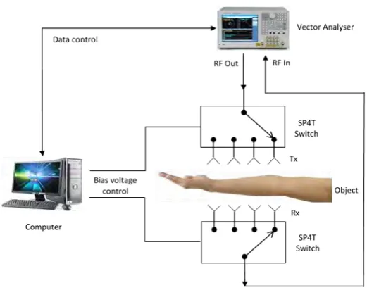
This project is part of the collaboration project between Faculty of Electronic and Computer Engineering (FKEKK) of Universiti Teknikal Malaysia Melaka (UTeM) with KPJ Healthcare University College to conduct a research in medical imaging and image processing. The project collaboration agreement letter is attached in Appendix A. In medical bone imaging system, the main component are signal source, switching circuit, transmitter and receiver antenna, biasing voltage control, and computer for the data collection as well as data processing.
2
Figure 1.1: Block diagram of medical bone imaging system
1.2 Problem statement
Osteoporosis or bone related issue have been a great issue, especially among women. On average, for people at age 50 and above there is 1 in every 2 women and 1 in every 5 man suffer from osteoporosis. To counter with osteoporosis and some other bone related diseases, bone monitoring system play a very important role as it is required for disease prevention, detection and treatment analysis. Currently, the commonly used bone scanning system are X-ray, Computerized tomography (CT) scan, and Magnetic Resonance Imaging (MRI). These old scanning technology have some disadvantages such as high production cost, bulky size of the machine and ionizing radiation effect that may threaten the health of body cells.
3
to maintain low insertion loss and high isolation at the same time over a wide operating frequency bandwidth.
1.3 Objectives
The purpose of doing this project is to select suitable diode topology and then design a Single Pole Four Throw (SP4T) switching circuit using the selected diode topology. The SP4T switch should have low insertion loss, high isolation and operates at large frequency band in order to support the microwave bone imaging system.
1.4 Scope of project
The scope of this project are:
i. Comparison and selection of suitable components that can works in the desired frequency range.
ii. Selection of suitable diode topology to be used in switching circuit design.
iii. Single pole four throw (SP4T) PIN diode switch design.
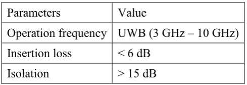
[image:21.595.197.442.576.660.2]The design and simulation is done using Advance Design System (ADS) software. This software helps in simulates and analyse the design to make sure the desired parameter of the switches are obtained. The substrate used is Rogers RO4350B. The design parameters of the switch is set as the value in Table 1.1.
Table 1.1: Design parameters of SP4T switch
Parameters Value
Operation frequency UWB (3 GHz – 10 GHz) Insertion loss < 6 dB
Isolation > 15 dB
1.5 Thesis outline
4
Chapter 2 reviews all related study done by other researcher and some background information about the current medical imaging technology.
Chapter 3 explains the process and how the project is carried out.
Chapter 4 contains all the results obtained through each stage of the project and discussion about the results.
5
CHAPTER 2
LITERATURE REVIEW
2 HEADING 3 – CHANGE COLOR TO WHITE BEFORE PRINTING
This chapter includes review of background, previous study or previous researches done on similar system, and also related theory which contributes a lot for better understanding, throughout this project.
2.1 Development of microwave imaging
Before the microwave imaging being applied in the field of bone imaging, this type of technique have already being developed for other application. One of the most related application filed is breast cancer detects scanning system, which is also human medication field. In the breast cancer detection system, a few type of microwave imaging system have been developed. Some example of the successful breast imaging system are Tissue Sensing Adaptive Radar (TSAR) [1] and microwave tomographic imaging (MTI) [2] techniques. The detection of breast cancer tissues is based on the electrical property (permittivity and conductivity) differences between normal cells and tumour cells [3]. With the aid of knowledge on signal scattering, when the transmitted signal hit the tumour tissues and the scattered signals received by multiple antennas from different direction, the confocal method by delay and sum algorithms can be used for the breast image reconstruction [4].
2.2 Potential of microwave imaging in bone imaging
6
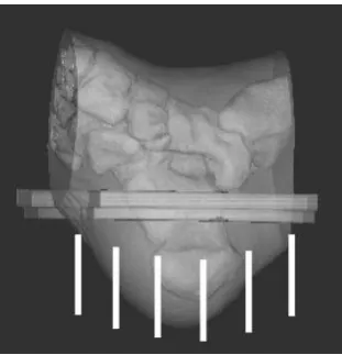
[image:24.595.260.413.143.310.2]imaging on the heels of injured patients to test the potential of MTI system. The imaged constructed was then compared to other scanning system such as MRI, CT scan, and Quantitative ultrasound (QUS).
Figure 2.1: MTI system with 16 monopole antennas positioned in circular array
Figure 2.2: Illustration of MTI scan on human heel
[image:24.595.259.415.379.541.2]