Int. J. Electrochem. Sci., 6 (2011) 1237 - 1249
International Journal of
ELECTROCHEMICAL
SCIENCE
www.electrochemsci.orgEffects of the Area of a Duplex Stainless Steel Exposed to
Corrosion on the Cathodic and Anodic Reactions in a LiBr
Solution Under Static and Dynamic Conditions
D.M. García-García, E. Blasco-Tamarit, J. García-Antón*
Ingeniería Electroquímica y Corrosión (IEC). Departamento de Ingeniería Química y Nuclear. ETSI Industriales. Universidad Politécnica de Valencia. P. O. Box 22012, E-46071 Valencia, Spain
*
E-mail: [email protected]
Received: 8 March 2011 / Accepted: 18 April 2011 / Published: 1 May 2011
The objective of the work was to study the influence of the exposed area of the working electrode on the corrosion behavior of a duplex stainless steel (EN 1.4462) in a 992 g/l LiBr solution under static conditions (without cavitation) and dynamic conditions (with cavitation) at 25 ºC. The Potentiodynamic Cyclic curves obtained were compared and different tendencies were observed. Cavitation increased the cathodic current density when the area exposed to the solution is large (diameters 6 and 8 mm). This behavior was not observed in the tests with smaller electrode areas (diameters 1.6 and 4 mm).
Keywords: Stainless steel, cavitation , passive film, pitting corrosion, repassivation
1. INTRODUCTION
Passive metals and alloys are usually prone to localized corrosion. The overall corrosion process consists of several steps starting with pit nucleation, where the passive film is destroyed locally, and a subsequently early growth stage, followed finally either by rapid repassivation (metastable pitting) or stable pit growth. The selection of more resistant materials requires a better understanding of the corrosion mechanisms and of the material response to different conditions of the medium.
In addition to the electrochemical effect, cavitation can occur in different points of refrigerating absorption systems (e.g. pumps, valves, pipes, bends). Cavitation consists of the appearance of vapor cavities inside an initially pure liquid medium due to drop in the static pressure. The phenomenon is usually undesirable to be undesired since it can cause changes in flow dynamics, drop of efficiency or head of hydraulic machines, noise and also severe erosion in the submerged surfaces. Liquid breakup can be achieved by different means although rapid local increase of fluid flow velocity and ultrasound can cause vibrations. Local increase of velocity can be generated by narrowing of the flow tract or by inserting an obstacle into the path of the fluid. For the latter, usually piezoelectric transducers that excite with frequencies in the range between 20 and 60 kHz [10, 11] are used to generate ultrasonic cavitation. Due to the inertia, the liquid cannot follow the oscillations of the sound field, and cavitation bubbles repeatedly appear and collapse.
The combined action of cavitation and corrosion is termed cavitation-corrosion. To reduce the risk of early component failure, the cavitation-corrosion processes need to be better understood.
The effect of electrolyte flows on corrosion is complex [12, 13]. This situation becomes even more complex when the system operates with highly concentrated solutions and solutions that can cause serious corrosion problems on metallic components. The main effect of cavitation is to increase the mass transport of species to and from the electrode surface [14, 15].
The aim of this work is to study the influence of the exposed area of the working electrode on the corrosion behavior of a duplex stainless steel (EN 1.4462) in a 992 g/l LiBr solution under static conditions (without cavitation) and dynamic conditions (with caviation) at 25 ºC
2. EXPERIMENTAL PROCEDURE
2.1. Materials and specimen preparation.
The material tested was duplex stainless steels: EN 1.4462. This stainless steel was provided by ACERINOX S.A. The composition of the tested duplex stainless steel is shown in Table 1.
Table 1. Composition of Duplex Stainless Steel EN 1.4462 tested.
Material Cr Ni Mn Si Mo Cu Fe S P C N Ti
EN 1.4462 electrodes were cylindrical specimens with different cross-sectional area: 0.02 cm2 (diameter: 1.6 mm), 0.13 cm2 (diameter: 4 mm), 0.28 cm2 (diameter: 6 mm) and 0.5 cm 2 (diameter: 8 mm). The electrodes were embedded in a non-conducting resin provided by Buehler. Before each experiment the electrodes were polished with emery paper down to 4000 grit, and rinsed with distilled water and acetone, and air-dried.
Experiments were carried out in Lithium Bromide aqueous solutions (992 g/L LiBr). The solution was prepared from purissimum LiBr (98 %wt) from PANREAC.
2.2. Microstructural examination
Microstructural examinations of specimens with different areas of duplex stainless steel were carried out using a LEICA DMLA 12000 microscope. Electrodes with different diameters were mechanically polished and chemically etched in Kalling’s reagent (5g CuCl2, 100 ml HCl and 100 ml
ethanol) [16, 17].
2.3. Static Conditions
Under static conditions, potentiodynamic anodic polarization measurements were determined according to ASTM G5 [18] at 25 ºC, using a Solartron 1287 potentiostat. The experimental arrangement consists of an electrochemical system with the data acquisition unit which registers the electrical signal obtained from the corrosion processes taking place inside an horizontal electrochemical cell [19,20].
The potential of the working electrode was measured vs a silver-silver chloride (Ag-AgCl) reference electrode with a 3 M potassium chloride (KCl) solution. The auxiliary electrode was a platinum (Pt) wire. Dissolved oxygen was removed from the LiBr solutions by bubbling nitrogen for 20 min. Before each anodic polarization measurement, the open-circuit potential (OCP) was measured for 1 h in the test solution. The average value of the potentials recorded during the last 300 seconds was accepted as the value of the OCP. The electrode potential was scanned from – 150 mVAg/AgCl vs
Ecorr to the anodic direction at 0.167 mV/s. When the current density reached 10 mA/cm2, the potential
scan was reversed in order to evaluate the repassivation tendency of the alloy. All tests were repeated at least three times in order to verify reproducibility. Temperature was maintained at 25 ºC during the tests.
Corrosion potential (Ecorr) and corrosion current density (icorr) were obtained from the log I-E
plot; furthermore, pitting potentials (Ep) were reported as the potential at which the current density
reaches 100 A/cm2. The current density before pitting is nearly constant and defined as the passive current density (ip).
In order to evaluate the repassivation tendency, the repassivation current density (irp), which
represents the maximum current density reached, and the repassivation potential (Erep), which was
2.4. Cavitation conditions
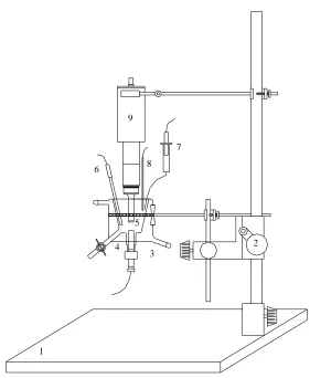
The experimental arrangement used consists of two parts: the ultrasonic-induced cavitation facility and the electrochemical cell (Figure 1). The working electrode is placed co-axially with the horn and is held stationary at a distance of 15 mm from the horn tip. This experimental arrangement is a modification of the standard ASTM G32 [21] test, which uses specimens mounted directly on the tip of the ultrasonic horn.
1
2 3
4 5 6
7
8 9
Figure 1. The experimental arrangement used for cavitation testing: (1) Base of the experimental arrangement; (2) Height adjustment; (3) Electrochemical Cell; (4) Working electrode; (5) Horn Tip; (6) Auxiliary Electrode (Platinum mesh); (7) Reference electrode (Ag/AgCl with 3 M KCl solution); (8) Temperature sensor; (9) Convertor of ultrasonic cavitation facility.
[image:4.596.160.441.206.548.2]
3. RESULTS AND DISCUSSION
3.1. Metallographical studies
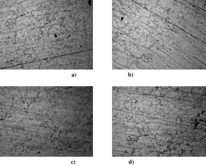
Figure 2 shows that the microstructure of the alloy presents a relatively homogeneous and equiaxed distribution of the austenitic and ferritic phases independently of the diameter of the electrode (1.6 mm, 4 mm, 6 mm and 8 mm). So then, it has been demonstrated that the microstructure of the alloy does not depend on the sample diameter. The austenitic phase (projecting phase) shows in the form of embedded islands in a matrix of -ferrite (sunken phase). The volume fraction of both phases was measured by image analysis, the volume fraction of austenitic is about 55% and the ferritic phase is 45%.
a) b)
c) d)
Figure 2. EN 1.4462 microstructure in a specimen with different cross-sectional area: (a) 0.02 cm2 (diameter = 1.6 mm); (b) 0.13 cm2 (diameter = 4 mm); (c)0.28 cm2 (diameter = 6 mm) and 0.5 cm 2 (diameter = 8 mm)
3.2. Influence of the area of the working electrode under static conditions
[image:5.596.90.509.275.614.2]
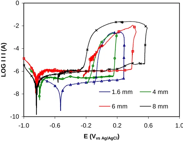
solution LiBr under static conditions to compare samples with different diameter. In this Figure 3, the influence of the area of the working electrode can be observed.
-10 -8 -6 -4 -2 0
-1.0 -0.6 -0.2 0.2 0.6 1.0
E (Vvs Ag/AgCl)
L
O
G
I I
I (A)
1.6 mm 4 mm
6 mm 8 mm
Figure 3. Cyclic potentiodynamic polarization curves for EN 1.4462 immersed in a 992 g/L LiBr solution under static conditions using different areas of the working electrode.
In all cases, the material shows a passive zone. In the case of the lager diameters (4 mm, 6 mm and 8 mm), the corrosion potential obtained is similar, around - 800 mV and the lowest current during the passive zone is registered for the 4 mm working electrode, 2.50 A/cm2. In general, a diminution in the electrode diameter produces a reduction in pitting potential. The area of the hysteresis loop reduces strongly as the surface area of the specimen decreases. During the sweep, the current increases with the larger working electrode areas.
[image:6.596.167.459.120.345.2]
Table 2 shows the electrochemical parameters obtained for working EN 1.4462 electrodes with different diameters in a 992 g/L LiBr solution under static conditions.
Table 2. Electrochemical Parameters of Duplex Stainless Steel EN 1.4462 obtained for different diameters of working electrode in a 992 g/L LiBr solution under Static Conditions.
Diameter
1.6 mm 4 mm 6 mm 8 mm
Ecorr (mVAg/AgCl) -525 -795 -838 -835
icorr (A/cm 2
) 0.52 0.56 0.73 0.38
(A) 0.01 0.07 0.21 0.19
ip (A/cm 2
) 5.59 2.17 3.78 2.50
(A) 0.11 0.27 1.06 1.04
Ep (mVAg/AgCl) 286 169 396 556
irep (mA/cm 2
) 145.5 18.1 40.9 47.0
(mA) 2.9 2.2 11.5 23.6
Erep (mVAg/AgCl) -83 -152 -177 -526
3.3. Influence of the area of the working electrode under cavitation conditions
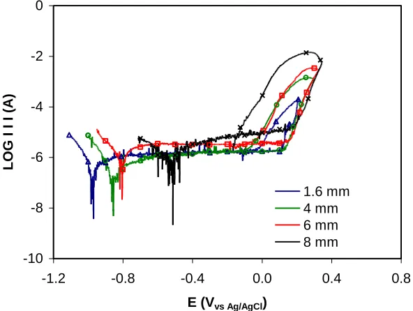
Similar experiments were repeated under cavitation conditions. The cyclic potentiodynamic polarization curves obtained for EN 1.4462 in the 992 g/l solution LiBr under cavitation conditions are shown in Figure 4.
-10 -8 -6 -4 -2 0
-1.2 -0.8 -0.4 0.0 0.4 0.8
E (Vvs Ag/AgCl)
L
O
G
I I
I (A)
1.6 mm 4 mm 6 mm 8 mm
[image:7.596.128.470.175.373.2] [image:7.596.151.447.495.718.2]
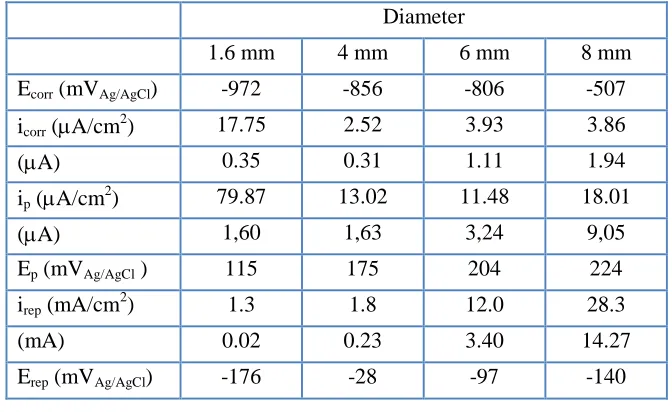
The reduction of the area produces a displacement of the corrosion potential, towards cathodic potentials. The highest corrosion current (1.94 A) is obtained for the largest diameter, 8 millimeters. The breakdown of the passive film is produced at a lower potential (pitting potential) when the diameter of electrode is reduced. Furthermore, the area of the hysteresis loop registered during the sweep decreases when the area of the working electrode is smaller. Table 3 summarizes the electrochemical parameters obtained for working EN 1.4462 electrodes in a 992 g/L LiBr solution under cavitation conditions.
Table 3. Electrochemical Parameters of Duplex Stainless Steel EN 1.4462 obtained for different diameters of working electrode in a 992 g/L LiBr solution under Cavitation Conditions.
Diameter
1.6 mm 4 mm 6 mm 8 mm
Ecorr (mVAg/AgCl) -972 -856 -806 -507
icorr (A/cm 2
) 17.75 2.52 3.93 3.86
(A) 0.35 0.31 1.11 1.94
ip (A/cm 2
) 79.87 13.02 11.48 18.01
(A) 1,60 1,63 3,24 9,05
Ep (mVAg/AgCl ) 115 175 204 224
irep (mA/cm 2
) 1.3 1.8 12.0 28.3
(mA) 0.02 0.23 3.40 14.27
Erep (mVAg/AgCl) -176 -28 -97 -140
3.4. Influence of cavitation on the corrosion behavior of the material
Making a comparison among the potentiondynamic curves obtained for EN 1.4462 in 992 g/L LiBr solution under corrosion conditions and cavitation-corrosion conditions with different diameters of the working electrodes, the influence of cavitation on the corrosion behaviour can be analyzed (Figure 5).
In the case of smaller diameters, Figure 5a (1.6 mm) and Figure 5b (4 mm), the cathodic reaction (cathodic branch during the potentidynamic sweep) is not modified by cavitation. When the diameter of the electrode is 6 mm (Figure 5c) and 8 mm (Figure 5d), cavitation produces an increment of the cathodic current density. The cathodic reaction is accelerated by the higher rate of mass transport developed under fluid jet impingement as indicated by the arrow in the graph (Figure 5c and 5d). It is clear that accelerating the mass transport of the cathodic reactant the cathodic reaction accelerates.
[image:8.596.130.466.258.464.2]
because of the impact by cavitation implies two apparently opposing effects on the Corrosion Potential values: the agitation of the medium increases the diffusion rates of the specimens (Factor 1), and cavitation decreases the thickness of the diffusion layer (Factor 2).
a) b)
c) d)
Figure 5. Cyclic potentiodynamic polarization curves for EN 1.4462 immersed in a 992 g/L LiBr solution under cavitation – corrosion conditions ( ) and corrosion conditions ( ) with working electrodes with different diameters 1.6 mm (a), 4 mm (b), 6 mm (c) and 8 mm (d).
Several authors [24-27] have reported the ennoblement of Corrosion Potential due to cavitation, and they have postulated that the agitation of the medium increases the diffusion rates of the specimens and the rate of the cathodic reduction reaction (Factor 1); hence, noble values of the Corrosion Potential are recorded. In aqueous LiBr solutions, the agitation associated with the generation and displacement of the bubbles into the medium produce an increase in the movement of the cathodic reactant to the surface of the metal [14,15], In this way, the cathodic reaction was favored over the anodic reaction, thus producing an ennoblement of the Corrosion Potential. In addition, corrosion of metals usually leads to the formation of dissolved metal ions at the corroding surface. These ions will diffuse towards the bulk solution and as a consequence a concentration gradient exists in the diffusion
-10 -8 -6 -4 -2 0
-1.2 -0.8 -0.4 0.0 0.4 0.8
E (Vvs Ag/AgCl)
L O G I i I (A/cm 2)
X Static Condition
Cavitation Condition -10 -8 -6 -4 -2 0
-1.2 -0.8 -0.4 0.0 0.4 0.8
E (Vvs Ag/AgCl)
L O G I i I (A/cm 2)
X Static Condition
Cavitation Condition -10 -8 -6 -4 -2 0
-1.2 -0.8 -0.4 0.0 0.4
E (Vvs Ag/AgCl)
L O G I i I (A/cm 2)
X Static Condition
Cavitation Condition -10 -8 -6 -4 -2 0
-1.2 -0.8 -0.4 0.0 0.4
E (Vvs Ag/AgCl)
L O G I i I (A/cm 2)
X Static Condition
Cavitation Condition
[image:9.596.95.511.153.516.2]
layer adjacent to the electrode. Similarly, in the case of transport of reactants in the presence of an excess of supporting electrolyte the dissolution current can be expressed as:
δ
) C (C D F n
i M M,s M,b
where M is used to designate the dissolving metal ion, n is the charge number, F is the Faraday’s constant, DM is the diffusion coefficient of the metal cation, CM,s is the concentration of the
metal cation at the surface, CM,b is the bulk concentration of the metal and is the thickness of the
diffusion layer.
Under static conditions (without cavitation), the thickness of the film does not change and its formation rate formation by metal oxidation at the film-metal interface equals its rate of dissolution at the film solution interface. Since dissolution is mass-transport controlled, a limiting current (ilim) is
observed given by:
δ
) C (C
D F n
ilim M M,sat M,b
Where: CM,sat is the saturation concentration of the transport limiting metal cation. The
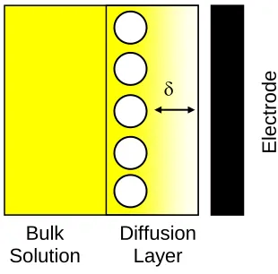
[image:10.596.184.421.445.617.2]described situation is schematically presented in Figure 6. In this Figure 6 it can be observed how the concentration of ions close to the electrode is modified by the applied potential.
Figure 6. Diffusion layer at the working electrode surface.
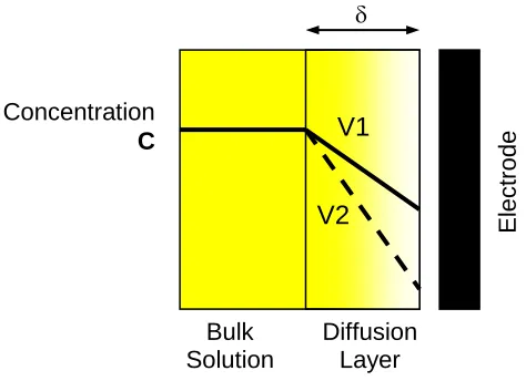
Applying stirring by ultrasonic agitation (cavitation) in the solution the thickness of the diffusion layer decreases (Factor 2), Figure 7, and so assit the electrode reaction. This reduction produces an increment in the current density registered during the anodic branch of the potentiodynamic polarization curves (Figure 5).
E
lectr
od
e
Concentration
C
Bulk Solution
Diffusion Layer
V1
Figure 7. Reduction of the diffusion layer at the working electrode surface by cavitaton in the solution.
These two factors have influence over the displacement of the corrosion potential. When the diameter of the working electrode is smaller (1.6 mm and 4 mm) cavitation decreases the thickness of the diffusion layer (Factor 2) and increases the anodic current density during the potentiodynamic polarization curves (Figure 5a and Figure 5b), so that the cathodic branch is not modified by cavitation. In this case, the corrosion potential shifts towards cathodic potentials.
Figure 5c (diameter: 6 mm) and Figure 5d (diameter: 8 mm) show that cavitation produces an increment of the cathodic reaction (Factor 1) and an increment of the anodic current density by the reduction of the diffusion layer (Factor 2) when the diameter is larger. In this case cavitation modifies both reactions and the corrosion potential shifts towards cathodic potentials because the influence of cavitation on the cathodic reaction is more important than on the anodic reaction.
The area of the working electrode influences the repassivation of the alloy (Figure 5). The reduction of the area of the hysteresis loop is higher when the working electrode area is the smallest (1.6 mm), in this case the area obtained under cavitation is around 80 % lower than the area obtained under static conditions. In the case of the other diameters, this reduction of the area of the hysteresis loop caused by cavitation is around 50 % in the 4 mm electrode and around 70 % in the 6 mm and 8 mm electrodes. This reduction is associated with the turbulence and elimination of products on the surface of the electrode.
It is known that a cover over the mouth of a metastable pit growing on stainless steel in a chloride and bromide solution is crucial to pit survival because this cover acts as a diffusion barrier in the metastable stage [28-30]. The pit cover is formed by the passive film which had originally covered the undissolved metal. Metal cations diffuse from the interior pit surface to the outside of the pit through a hole in this cover. In a mechanically quiescent system the cation concentration in the electrolyte outside the pit is the highest above the hole and decreased radially with a distance from the pit mouth. Under cavitation conditions, turbulent flow washes the electrode surface. The locally highly aggressive anolyte over the hole on the pit cover is diluted by the impinging solution through accelerated diffusion, accelerating diffusion of cations from within. Thus the concentration of metal cations inside the pit decreases and the pit repassivates. This rationale also supports the notion that
E
lectr
od
e
Bulk Solution
growth of a pit is diffusion controlled, not ohmically controlled, because the ohmic potential drop in the solution cannot vary with solution velocity [31].
Another rationale is that cavitation causes the mechanical rupture of a metastable pit cover, widening the hole access; when the pit cover is lost, the pit anolyte dilutes because of accelerated diffusion through the widened pit mouth and the pit repassivates. The pit cover is ruptured more readily by the pressure induced by cavitation than by a stagnant solution.
Therefore a reduction in the area of the working electrode favours the repassivation of the alloy associated with cavitation.
4. CONCLUSIONS
The rupture of the passive film by pitting is modified when the area of the working electrode is modified. This rupture is registered at higher potentials when the diameter is reduced to small values (microelectrodes).
Under static conditions, without cavitation, the area of the working electrode has influence over the reduction of the medium (cathodic branch during the potentiodynamic tests) and over the formation of the passive film (anodic branch). The reduction of the medium is favored when the area of the electrode is lower, on the contrary the anodic current is increased when the area exposed to the solution is larger.
Under cavitation conditions, the increment of the area favors the reduction reaction of the medium (cathodic branch during the potentiodynamic tests) and the anodic current during the formation of the passive film (anodic branch). The influence of cavitation on the corrosion potential depends on two factors: agitation of the medium by cavitation increases the diffusion rates of the specimens and it increases the rate of the cathodic reduction reaction (Factor 1); Cavitation decreases the thickness of the diffusion layer during the formation of the passive film (Factor 2). The importance of each factor depends of the area on the working electrode.
The area of the working electrode influences the repassivation of the alloy. This repassivation is favored when the area of the working electrode is reduced.
ACKNOLEDGEMENTS
We wish to express our gratitude to Ministerio de Ciencia e Innovación (CTQ2009-07518/PPQ), to FEDER for their financial support and to Dr. M. Asunción Jaime for her translation assistance.
References
1. J. W. Furlong, The Air Pollution Consultant, Elsevier Science Inc., (ed.) (1994). 2. K. Gilchrist, R. Lorton, R. J. Green, Appl. Therm. Eng. 22 (2002) 847.
3. J. L. Guiñón, J. García Antón, V. Pérez-Herranz, G. Lacoste, Corrosion 50 (1994) 240.
5. K. Tanno, M. Itoh, T. Takayashi, H. Yashiro, N. Kumagai, Corros. Sci . 34 (1993) 1441. 6. E. Sarmiento, J.G. González-Rodriguez, J. Uruchurtu, O. Sarmiento and M. Menchaca, Int. J.
Electrochem. Sci., 4 (2009) 144.
7. M.T. Montañés, R. Sánchez-Tovar, J. García-Antón, V. Pérez-Herranz, Int. J. Electrochem. Sci., 5 (2010) 1934.
8. X. Hu, Ch. Liand, Mater. Chem. Phys. 104 (2007) 68.
9. K. Tanno, M. Itoh, H. Sekiya, T. Takayashi, N. Kumagai, Corros. Sci . 34 (1993) 1453. 10.B. Zequiri, M. Hodnett, A. J. Carroll, Ultrasonics 44 (2006) 73.
11.G. O. H. Whillock, B. F. Harvey, Ultrason. Sonochem. 4 (1997) 33.
12.J. Mendoza-Canales and J. Marín-Cruz, Int. J. Electrochem. Sci., 3 (2008) 346-355.
13.A.Y. Musa, A.A.H. Kadhum, A. Bakar-Mohamad, A. Razak-Daud, M. Sobri-Takriff, S. Kartom-Kamarudin and N. Muhamad, Int. J. Electrochem. Sci., 4 (2009) 707.
14.D. M. García-García, J. García-Antón, A. Igual-Muñoz, E. Blasco Tamarit, Corros. Sci . 48 (2006) 2380.
15.D. M. García-García, J. García-Antón, A. Igual-Muñoz, E. Blasco Tamarit, Corrosion 63 (2007) 462.
16.L. F. Garfias Mesias, J. M. Sykes, C. D. S. Tuck, Corros. Sci . 38 (1996) 1319.
17.G. Fargas, M. Anglada, A. Mateo. Influencia de las fases intermetálicas en la conformación de los aceros inoxidables dúplex. VIII National Congress of Solid Mechanical Properties, Gandia (Spain) 2002.
18.ASTM G-5, Test Method for Making Potentiostatic and Potentiodynamic Anodic Polarization Measurements, 2004.
19.J. García Antón, A. Igual Muñoz, J. L. Guiñón, V. Pérez-Herranz, P-200002525 Spain (2001). 20.J. García Antón, A. Igual Muñoz, V. Pérez-Herranz, J. L. Guiñón, P - 200002526 Spain (2000). 21.ASTM G32 - 98: "Standard Test Method for Cavitation Erosion Using Vibratory Apparatus". Ed.
ASTM. 1998.
22.K. Sasaki, G. T. Burstein, Corros. Sci . 49 (2007) 92.
23.G. T. Burstein, G. O. Ilevbare, Corros. Sci . 38 (1996) 2257. 24.A.Neville, T. Hodgkiess, Corros. Sci.. 38 (1996) 927.
25.V. Scotto, Di. R. Cintio, G. Marcenaro, Corros. Sci . 25 (1985) 185. 26.P. Gallagher, R. E. Malpas, E. B. Shone, Br. Corrosion J. 23 (1988) 229. 27.J. Wallen, S. Henrikson, Werkstoffe Korros 40 (1989) 602.
28.P. C. Pistorius, G. T. Burstein, Phil. Trans. R. Soc. 341 (1992) 531. 29.P. C. Pistorius, G. T. Burstein, Corros. Sci . 33 (1992) 1885.
30.H. S. Isaacs, B. F. Brown, J. Kruger, R. W. Staehle, Corrosion (1974) 158. 31.K. Sasaki, G. T. Burstein, Corros. Sci . 49 (2007) 92.