Iowa State University Patents
Iowa State University Research Foundation, Inc.
3-30-1999
Mobile inductivity
Arthur P. D'Silva
Iowa State University
Edward J. Jaselskis
Iowa State University
Follow this and additional works at:
http://lib.dr.iastate.edu/patents
Part of the
Chemistry Commons, and the
Environmental Engineering Commons
This Patent is brought to you for free and open access by the Iowa State University Research Foundation, Inc. at Iowa State University Digital Repository. It has been accepted for inclusion in Iowa State University Patents by an authorized administrator of Iowa State University Digital Repository. For more information, please [email protected].
Recommended Citation
D'Silva, Arthur P. and Jaselskis, Edward J., "Mobile inductivity" (1999).Iowa State University Patents. 58.
hazardous site is connected to an optical fiber, which directs laser radiation proximate the material at the
hazardous site. The laser radiation abates a sample of the material. An inductively coupled plasma is located
remotely from the material. An aerosol transport system carries the ablated particles to a plasma, where they
are dissociated, atomized and excited to provide characteristic optical reduction of the elemental constituents
of the sample. An optical spectrometer is located remotely from the site. A second optical fiber is connected to
the optical spectrometer at one end and the plasma source at the other end to carry the optical radiation from
the plasma source to the spectrometer.
Keywords
Ames Laboratory, Civil Construction and Environmental Engineering
Disciplines
Chemistry | Civil and Environmental Engineering | Environmental Engineering
United States Patent
[19JD'Silva et al.
[54] MOBILE INDUCTIVELY COUPLED PLASMA
SYSTEM
[75] Inventors: Arthur P. D'Silva; Edward J.
Jaselskis, both of Ames, Iowa
[73] Assignee: Iowa State University Research
Foundation, Ames, Iowa
[21] Appl. No.: 117,242
[22] Filed: Sep. 3, 1993
Related U.S. Application Data
[63] Continuation of Ser. No. 770,524, Oct. 3, 1991, abandoned.
[51] [52] [58]
[56]
Int. Cl.6
... GOlJ 3/30
U.S. Cl. ... 356/316 Field of Search ... 356/315-316,
3,521,959 4,598,577 4,802,761 4,986,658 5,085,499 5,104,391
356/318-319, 36
References Cited
U.S. PATENT DOCUMENTS
7/1970 Passel eta!. ... 356/316 7/1986 Jowitt eta!. ... 356/36 2/1989 Bowden et a!. ... 356/301 1!1991 Kim ... 356/318 2/1992 Griffin et a!. ... 356/316 4/1992 Ingle et a!. ... 356/73.1 X
FOREIGN PATENT DOCUMENTS
0200446 9/1986 Japan ... 356/316
LASER
111111
1111111111111111111111111111111111111111111111111111111111111
US005889587 A
[11]
Patent Number:
[45]
Date of Patent:
5,889,587
Mar. 30, 1999
OTHER PUBLICATIONS
Brewer et al., "Studies of Aerosols Generated by Electrically Vaporized Thin Films for ICP-AES", Applied spectroscopy, vol. 44, No. 3, 1990, 356/316.
Jin et al., "An Efficient and Inexpensive Ultrasonic Nebu-lizer for Atomic Spectroscopy", Applied spectroscopy, vol. 44, No. 2, 1990,
Article of 46 Photonics Spectra, June 1991.
Primary Examiner--K. P. Hantis
Attorney, Agent, or Firm---Schwegman, Lundberg, Woessner, and Kluth, P.A.
[57] ABSTRACT
A system for sampling and analyzing a material located at a hazardous site. A laser located remote from the hazardous site is connected to an optical fiber, which directs laser radiation proximate the material at the hazardous site. The laser radiation abates a sample of the material. An induc-tively coupled plasma is located remotely from the material. An aerosol transport system carries the ablated particles to a plasma, where they are dissociated, atomized and excited to provide characteristic optical reduction of the elemental constituents of the sample. An optical spectrometer is located remotely from the site. A second optical fiber is connected to the optical spectrometer at one end and the plasma source at the other end to carry the optical radiation from the plasma source to the spectrometer.
17 Claims, 5 Drawing Sheets
FIG. I
32
/10
40
12
LASER
64
FIG. 2
66
60
J
14
76
U.S. Patent
Mar. 30, 1999
Sheet 2 of 5
5,889,587
FIG. 3
16
73
102
---14
-104
\ \
I \
I
I
94
25
98
16
II 0
--~I97
117-116
114
FIG. 5
20
- 26
\
94
14
FIG. 6
U.S. Patent
Mar. 30, 1999
64
FIG. 8
Sheet 4 of 5
FIG. 7
121
5,889,587
ItS
120
FIG. 9
32
40
12
LASER
22
18
26
FIG. 10
40
38 36 37 34
32
ICP
28
5,889,587
1
MOBILE INDUCTIVELY COUPLED PLASMA SYSTEM
The Instant Application is a continuation of Ser. No. 07/770,524, filed Oct. 3, 1991, now abandoned.
The invention was made with support under contract with the Department of Energy Contract No. W-7405-ENG-82. The Government has certain rights in the invention.
TECHNICAL FIELD OF THE INVENTION
This invention pertains generally to the field of material analysis, and more particularly to method and apparatus for acquisition of a material sample from a remote site and subsequent analysis of the sample.
TECHNICAL FIELD OF THE INVENTION
2
sample on a filter media, which is taken to a remote site for analysis using the inductively coupled plasma system dis-cussed above.
Finally, an ultrasonic or direct injection nebulization
5 technique is used instead of the laser to produce aerosol
particles from liquid materials at the sampling site to be analyzed by the ICP.
BRIEF DESCRIPTION OF THE DRAWINGS
10
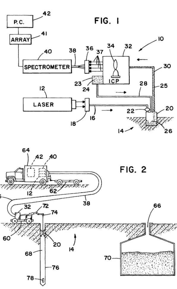
FIG. 1 provides a schematic illustration of the mobile
inductively coupled plasma system of the present invention; FIG. 2 illustrates one application of the mobile induc-tively coupled plasma system of the present invention for
15 sampling soil at a hazardous waste site;
FIG. 3 is a detailed illustration of one type of probe of the preferred embodiment of the present invention;
There is often the need for sampling and analysis of dangerous or hazardous materials, or materials located in
hazardous environments. Examples include sampling and 20
analyzing the condition of soil or water at hazardous waste sites (radioactive wastes, toxic chemical dumps or contami-nated structures) or of molten metals in a manufacturing foundry. Conventionally, a sample of a hazardous waste is
removed from the site and brought to a laboratory for 25
analysis. The sample must therefore be carefully extracted, transported, handled and stored in order to assure the safety
FIG. 4 illustrates an alternate sealing system for a probe
which obtains samples from surface soil;
FIG. 5 illustrates another alternate sealing system for
obtaining material samples from hard and uniform surfaces; FIG. 6 is a detailed illustration of an alternate embodiment of the probe to be used to sample molten materials;
FIG. 7 illustrates an alternate embodiment of the mobile inductively coupled plasma system of the present invention where the laser and optical spectrometer are located on the mobile cart;
of the technicians carrying out the test, as well as the public. The expense and delay entailed in extracting, handling and storing such materials, as well as the health risks, have encouraged scientists to develop alternative testing approaches minimizing these disadvantages.
BACKGROUND OF THE INVENTION
FIG. 8 is a schematic of an alternate embodiment of the
30 present invention where the ablated sample is collected on a
filter media;
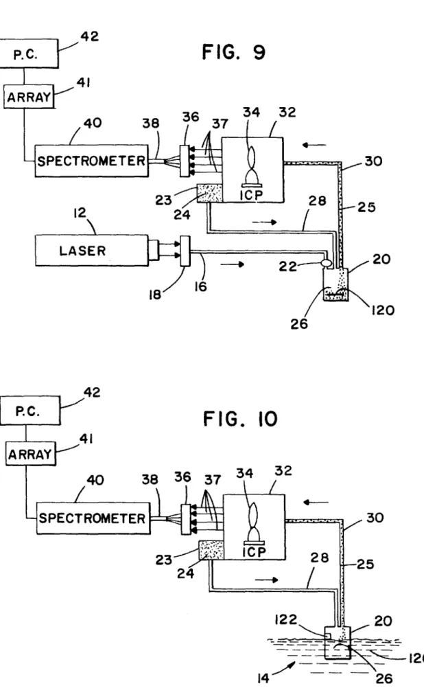
FIG. 9 is a schematic of an alternate embodiment of the present invention where the filter media is subject to ablation for purposes of analyzing the sample; and
The present invention provides a method and apparatus 35
for sampling and analyzing hazardous materials proximate the site and such that a an absolute minimum of hazardous material need be released or removed from the site.
FIG. 10 is a schematic of the mobile inductively coupled
plasma system of the present invention for use in sampling and analyzing liquid materials.
According to one aspect of the invention, a remotely
40
controlled mobile cart positions a probe proximate to the sampling site. A high energy wavelength laser ablates the material, forming a cloud of micron-sized particles. The particles are drawn from the sampling site by an aerosol system which employs an inert gas, such as argon. The
45
sample particles and argon gas aerosol are injected into an inductively coupled plasma (ICP) source, which produces electromagnetic radiation which can be analyzed with an optical spectrometer.
DETAILED DESCRIPTION OF THE PREFERRED EMBODIMENT
FIG. 1 provides a simplified schematic illustration of the
mobile inductively coupled plasma system 10 of the present
invention. Laser radiation from an ultraviolet laser 12 is
directed to the sampling site 14 through fused silica fiber rod
optics 16. Preferably, the laser provides continuous or
pulsed, fixed wavelength laser radiation at at least three different wavelengths, 1064 nm, 532 nm, and 355 nm. These wavelengths are chosen to provide a range of energies as In one embodiment, the laser source is located in a van or
truck remote from the cart, with the laser beam from the source carried to the probe over an optical fiber. The inductively coupled plasma source is located on the mobile cart, with its optical output being carried over another optical fiber to an optical spectrometer located in the van or truck, from which the material analysis is obtained. In another embodiment, the laser and spectrometer are located on the cart.
The present invention also employs several unique probe structures which isolate the sampling site from the outside environment, ensuring that only the material ablated by the laser radiation is carried to the inductively couple plasma system (ICP) through the aerosol transport system. A special ceramic probe tip is employed to extract samples from molten materials.
Because length over which the aerosol system can carry the ablated sample, another embodiment collects the ablated
50 materials to be analyzed have different absorption
charac-teristics at different wavelengths. Since current optical fibers are subject to damage at wavelengths below 350 nm and power levels of 108 watts/cm2/sec., it is best to utilize laser
wavelengths above 350 nm. These constraints will change
55 with the availability of better optical fibers. As most
mate-rials absorb optical radiation in the ultraviolet, ablation is more efficiently carried out at wavelengths below 400 nm. The Lumonics Dye Laser (Hyper-Dye 300) pumped by the Lambda Physik Excimer Laser (model EMG102MSC) is
60 known to provide laser beams suitable for use in the present
invention, although the preferred system for field operation is the solid state YAG laser.
A laser focusing system 18 is provided to focus the laser
output onto the optical fiber 16, without overloading it. C
65 Technologies fiber optics cable model SRA-6-1-20-01 is
known to be suitable for carrying the laser radiation to a
preferred embodiment of the present invention has achieved reduce the power actually received by the optical fiber and
a series of lenses to focus the laser radiation onto the end of the optical fiber.
5 transportation of material samples 25 in the aerosol line 30
to a distance of 100 feet.
The laser source 12 and spectrometer 40 are located in the
truck 64. As explained above with respect to FIG. 1, an
optical fiber 16 carries the laser beam from the laser 12 to the
10 probe 20, while a second fiber 38 carries the output of the
ICP 32 to the spectrometer 40. Using the equipment
speci-fied herein, the laser beam can be carried up to 30 meters on the fiber 16. Similarly, fiber 38 can carry the output of the As will be discussed in more detail below with respect to
FIG. 3, the probe 20 has optics 22 for focusing the laser
radiation from the fiber 16 on the material to be sampled 14.
The probe 20 is generally constructed of aluminum, but
other materials may be preferable to contend with different
environmental conditions. An argon gas source 23 supplies
argon gas 24 to a probe sampling chamber 26 through an
aerosol input line 28. The material ablated or sampled 25 by
the laser radiation mixes with the argon 24 to form an 15
aerosol which is drawn from the probe sampling chamber 26
through the aerosol output line 30 to the inductively coupled
plasma (ICP) source 32. Argon 24 is the support gas for the
ICP 32. The present invention employs an RF Plasma
Products® inductively coupled argon plasma system. As is conventional in the art, the aerosol is directed into
the plasma source 34, through an input line (not shown) to
the ICP 32. The energized sample particles are excited to
provide characteristic optical reduction of the elemental
constituents of the sample 25 in the form of electromagnetic
radiation 37, which is focused by a lens 36 and thereby
subsequently channeled through an ICP output optical cable
ICP 32 about 30 meters to the spectrometer 40.
The probe 20 is attached to a three-axis robot arm 72
mounted to the cart 60, which is also controlled remotely by
the operator, preferably using images relayed from a video camera mounted on the platform or even on the probe itself.
In the application shown in FIG. 2, the operator controls the
20 robot arm 72 to position the probe 20 over the center of the
sampling bore 68. The tubes 28 and 30 and fiber 16, a
load-bearing cable 73, and other necessary electronic cables
(not shown) are wound on a spool with a winch 74, which
is remotely controlled to lower and raise the probe 20. In the
25 preferred embodiment of the present invention, the sampling
bore 68 contains a liner 76 (shown in more detail in FIG. 3),
which can be a conventional pipe with a cut-out area, or
window 78, through which access to the sampling site 14 is
38 to a remotely located multi-channel or sequential optical
spectrometer 40. To carry the optical output of the ICP 32 to
the spectrometer 40, the preferred embodiment of the 30
present invention employs Polymicro Technologies fiber optic bundle (model PTA-LEI0019FF-030-0DP), consisting
obtained.
The probe 20 is lowered into the sampling bore 68 until
it is adjacent to the sampling window 78. The sampling thus
proceeds with the operators at a safe distance from the
sampling site 14. When sampling is completed, the probe 20
of 19 separate 200 ,urn core diameter fibers arranged in a round-to-linear bundle. The Acton Research Corp. 0.5 meter spectrometer (model VM-505) equipped with a 2400 grooves/mm grating has been found suitable as the spec-trometer. The optical radiation dispersed in the spectrometer
35 is withdrawn from the sampling bore 68 and the remotely
controlled mobile cart 60 is returned to the trailer 62 for
is detected by a multichannel diode array detector 41. The
EG&G Princeton Applied Research intensified diode array
(model1420) and diode array controller (model 1463) are 40
known to be suitable for this purpose. Preferably, the IEEE
output of the detector 41 is connected to a personal computer
42 or workstation whereby the output of the spectrometer 40
can be stored, enhanced, processed, analyzed, and displayed.
45
FIG. 2 illustrates one embodiment of the mobile
indue-transportation to the next site. If any contamination has
occurred, it is generally limited to the probe 20 or the
immediate accessories (i.e., cables, etc.), allowing relatively
easy clean-up. The sample 25 itself is incinerated in the ICP
plasma source 34. If necessary, the probe 20 and accessories
can be disposed of or destroyed and replaced at relatively low cost.
FIG. 3 illustrates one embodiment of the sampling probe
20 of the present invention. Alignment wheels 90 are
attached to the leading and trailing edges of probe 20 by
flexible support members 92. The alignment wheels 90
allow the probe 20 to be lowered into the liner 76 without
jamming. The probe 20 is lowered until a probe window 94
tively coupled plasma system 10 of the present invention. A
remotely controlled mobile cart 60 is trailered on a trailer 62
behind a truck 64. The truck 64 contains a power source for
operating the components of the system. In use, the truck 64
50 is aligned with the sampling window 78. Inflatable seals 96
are filled with compressed air from a pressurized source (not
shown) so as to seal the sampling window 78 and the probe
window 94 from the outside environment.
is positioned a distance from the toxic waste sampling site
14. The remotely controlled mobile cart 60 is then
posi-tioned proximate to the sampling site 14, for instance a
sampling bore 68 adjacent to the toxic waste storage
cham-ber 70, by direct visual reckoning or by use of video images 55
relayed from a video camera (not shown) mounted on the
cart 60. The controls for maneuvering cart 60 are located in
the truck 64.
In the preferred embodiment of the present invention, the
remotely controlled mobile cart 60 carries the ICP source 32,
so that the ICP source is as close to the sampling site 14 as possible, thereby minimizing the distance the hazardous
material needs to be transported in the aerosol output line 30
and to keep the hazardous material away from the operators positioned in the truck 64.
In the preferred embodiment, the aerosol tubes 28 and 30
are 0.25" in diameter, made of Teflon® or polyethylene
The sampling process entails focusing the laser radiation
carried on the fiber 16 through a convex lens 22, which is
located either inside or outside the probe sampling chamber
26, depending on the design chosen. The fiber 16 is secured
to the probe 20 via bracket 95. In FIG. 3, the lens 22 is
mounted outside the probe 20 on a telescoping support 98
60 with an integral stepper motor (not shown), which allows the
convex lens 22 to be positioned to focus the laser beam on
the material to be sampled 14, using stepper motor controller
102. An Oriel stepper motor (model 18512) and controller (model20010) are known to be suitable for this purpose. The
65 laser radiation passes through a transparent covering 99 over
the opening 97 in probe 20, which isolates the sampling
environ-5,889,587
5
6
x and y degrees of freedom, controlled by stepper motor and
controller 102 (not shown). The Oriel stepper motor (model
18512) and controller (model 20010) discussed above are known to be suitable for this purpose. The free end of the mental integrity of the sampling process. A special rotating
polygon mirror 100 at the base of the sampling chamber 26
reflects the beam onto the material, providing x and y axis
rastering across the sampling site 14. Other approaches
utilizing stepper motors configured to provide x-y and rotary motion can also be utilized. As will be discussed in more detail below, the operator monitors the intensity of the
silicon spectra line generated by the optical spectrometer 40
5 fiber 16 is fixed relative to the base 110 using an armature 112, to keep it aligned over the lens as the base 110 moves.
The moveable base 110 is remotely activated to direct the
laser radiation in a raster scanning pattern across the
sam-to determine if the convex lens 22 is properly positioned to
create the optimum focal length. 10
pling site 14.
A perforated elastic tubular member, or seal, 106 is placed
around the outside perimeter of the probe window 94. The
perforated seal106 is preferably constructed of polyethylene foam or some other suitably porous material. Water is
provided by a water line 108 to moisten the perforated seal
15 106 and soil surrounding the sampling site 14. The moisture
operates to seal the sampling chamber 26 from the outside
A variable speed motor 104 is remotely activated to rotate
the polygon mirror 100, and direct the laser radiation in a
raster scanning pattern across the sampling site 14. In the
preferred embodiment of the present invention, scanning is
performed at a rate of 5-10 millimeters per second. It is
important that the laser radiation is sufficient to ablate the material to be sampled to create sufficiently small particles
that can be transported through the aerosol output line 30.
However, localized melting of the material should be
avoided, since melting can change the composition of the 20
sample material 25, leading to erroneous spectral analysis.
Accordingly, the laser power (or wavelength) may need to be varied depending on the material being sampled. Further information on laser ablation is set forth in the paper entitled
"Laser Vaporization in Atomic Spectroscopy," by H. K. 25
Dittrich and R. Wennrich, Prog. Analyt. Spectrosc., 7,
139-198 (1984), the entire contents of which are hereby incorporated by reference herein.
Argon 24 is forced into the probe sampling chamber 26
through the aerosol input line 28. The ablated sample 30
particles 25 become mixed with the argon gas 24 and are
subsequently drawn from the probe sampling chamber 26
through the aerosol output line 30. As discussed above, the
aerosol output line 30 directs the mixture of argon gas 24
and sample particles 25 to the ICP plasma source 34. 35
As soon as the laser 12 is activated to initiate sampling of
a soil, the operator observes the spectrometer 40 output for
signs of silicon, since silicon is present in virtually all soils.
The position of the convex lens 22 in the sampling chamber 40
26 is adjusted, by stepping the telescoping support 98, until the intensity of the silicon line in the spectrometer is maximized. At this point, the focal length of the laser radiation is correctly adjusted to focus the beam on the material to be sampled. Rastering can be performed during
45
adjustment of the focus or initiated immediately after focus is achieved. By rastering, localized melting can be avoided and a relatively large sample area can be covered. In the
preferred embodiment, a sample area of 1 inch2 is covered
during rastering. When sampling is completed, the air is
50
released from the seals 96 and the probe 20 is withdrawn
from the sampling bore 68 by the three axis robot arm 72.
FIG. 4 illustrates an alternative configuration for sealing
the probe 20 against the material to be sampled. The probe
20 of FIG. 4 is not shown attached to the cable 73 or the 55
3-axis robot arm 72 since some applications of the present
invention will permit the probe 20 to be placed on the
sampling site 14 manually. For example, where the material
to be sampled is not toxic to humans. However, it will be
understood by those skilled in the art that any of the probe 60
configurations disclosed herein can be attached to a variety of devices for locomotion.
Like the embodiment of FIG. 3, a convex lens 22 and
telescoping support 98 are mounted to the top of the probe
20 for focusing the laser radiation through the transparent 65
covering 99 to the correct focal length. Preferably, the
telescoping unit 98 is mounted to a moveable base 110 with
environment.
FIG. 5 illustrates yet another method to seal the probe 20
against the material to be sampled. The probe again requires
a similar convex lens 22 and telescoping support 98 for
focusing the laser radiation onto the sampling site 14. The
moveable base 110 is remotely activated to move the end of
the fiber 16 in a raster scanning pattern. The probe 20 is
attached to the 3-axis robot arm 72 so that it can be
positioned in a variety of angles. An inflatable seal 96 is
provided around the probe window 94, which is filled with
compressed air during the sampling process. The
configu-ration of FIG. 5 is intended primarily for sampling on
substantially smooth surfaces, such as walls and ceilings of buildings. However, a variety of methods are available for
isolating the probe chamber 26 from the outside
environ-ment during sampling.
FIG. 6 illustrates the use of the mobile inductively
coupled plasma system of the present invention for sampling
molten metals and alloys 116. The probe 20 is constructed
similar to that disclosed in FIGS. 4 and 5. The convex lens
22 and telescoping support 98 are mounted inside the probe 20 to protect them from heat. As discussed above, the
telescoping unit 98 is mounted to a moveable base 110 with
x and y degrees of freedom to move the free end of the fiber 16 in a raster scanning pattern across the sampling site 14.
A thermally resistant hollow ceramic probe tip 114 is
mounted to the sampling end of the probe 20. The ceramic
tip 114 is used to penetrate the slag layer on the top of the
molten metal116, thereby exposing the molten metal below.
The water lines 108 provides cooling liquid to a cooling
chamber 117, which is located between the optics 22 and the
ceramic probe tip 114. Sampling occurs in the sampling
chamber 26, as discussed in detail above.
FIG. 7 illustrates an alternate embodiment of the mobile inductively coupled plasma system of the present invention
where the laser 12 and optical spectrometer 40 are located on
the mobile cart 60, along with the diode array 41. The
electrical output signals from the diode array 41 are carried
by cable 124 to the computer 42 in the truck 64.
FIGS. 8 and 9 illustrate yet another embodiment of the mobile inductively couple plasma system of the present invention. As discussed above, the aerosol system (argon gas
source 23 and argon gas 24) of the present invention has
achieved transportation of material samples 25 in the aerosol
line 30 to a distance of 100 feet. However, the toxic or
radioactive nature of some sampling sites 14 may require
that the sample be transported more than 100 feet in the aerosol, or it may not be possible for the material to be easily
carried on the aerosol. FIG. 8 illustrates a system were the
sub-micron sized pores to insure capturing sufficient sample
25 material. However, the pore size of the filter paper may 5
vary depending on the material being sampled.
Argon gas 24 can be allowed to escape from the top of the
filter paper chamber 118. A meter 121 is located proximate
to the top of the filter paper chamber 118 to monitor the
quantity of argon gas 24 present. As the pores of the filter 10
media 120 become clogged with sample material 25, the
quantity of argon gas 24 flowing through the filter media 120
will decrease, with a corresponding decrease in the quantity
of argon 24 detected by the meter 121. When the quantity of
argon gas 24 detected by the meter 121 drops to a prede- 15
termined level, sampling is terminated.
the inductively coupled plasma source and receiving the output emission of said inductively coupled plasma source, an output of the detector providing an indica-tion of the elemental constituents of the sample. 2. The system of claim 1 further wherein said sampling probe comprises:
a housing defining a sampling chamber in communication with said aerosol transport system, the chamber having an opening for receiving the sample; and
a lens on an adjustable support mounted to the housing, the lens interposed between said second end of said first optical fiber and the material to focus and direct said laser beam through said opening onto the material, so that said aerosol transport system carries the sample to the plasma source.
3. The system of claim 1 further wherein the sampling The filter media is then removed from the toxic site for
analysis. FIG. 9 illustrates a laser ablation system for
analyzing the sample 25 collected on the filter media 120.
The filter media 120 is placed in the probe 20, where it is
subject to the laser ablation process discussed above.
FIG. 10 illustrates the use of an ultrasonic nebulizer to
produce aerosol 25 from liquid material 126. In principle,
when ultrasonic waves from a transducer 122 of sufficient
frequency and amplitude are produced, a capillary wave
action is induced in a liquid medium 126, causing the
ejection of aerosol droplets from the liquid surface. The droplets, the dimensions of which are dependent on the ultrasonic frequency and physical properties of the liquid, can be produced with micron sized diameters. By
synchro-nizing the transducer 122 frequencies and focusing the
ultrasonic waves to a single point, a wave pattern should be generated with an amplitude sufficient to provide the
quan-tities of sample 25 required for ICP 32 analysis. A low
frequency, high power, ultrasonic step horn generator known to be suitable for the present embodiment is disclosed by
Passel and Dickinson, Anal. Chern. 40, 1968, 247; and in
U.S. Pat. No. 3,521,949. Once a representative aerosol
sample 25 is generated, it mixes with the argon 24 and is
20 probe comprises a housing defining a sampling chamber in
communication with said aerosol transport system, the chamber having an opening for receiving the sample, whereby said aerosol transport system carries the particles to the plasma source.
25 4. The system of claim 3 further including rastering means
for rastering said laser beam across the material.
5. The system of claim 2 further including seal means
attached to the housing proximate to said opening for engagement with the surface of the material to be sampled
30 for substantially isolating said sampling chamber and the
material from the outside environment during sampling.
6. The system of claim 3 further wherein the opening is
defined on an end of said probe and the end of the probe is constructed of a thermally resistant material.
35 7. The system of claim 1 wherein a sample of particles is
ablated from the material by the laser, and wherein the detector is an optical spectrometer.
transported to ICP 32 for analysis. 40
The nebulized liquid material 126 is drawn through the
aerosol output line 30 to the ICP 32. Sample analysis
proceeds as discussed in detail above.
It will be understood that the present invention is not
45
limited to the examples discussed above, but may be changed or modified without departing from the spirit or scope of the invention.
8. The system of claim 1 further where the sampling probe includes a filter for collecting the sample of the material; and the detector is an optical spectrometer in optical
commu-nication with said inductively coupled plasma source to receive said electromagnetic radiation.
9. The system of claim 1, further comprising a second
optical fiber having a first end proximate the inductively coupled plasma source for collecting the output emission and a second end proximate the elemental constituent detec-tor for delivering the output emission to the elemental constituent detector.
We claim:
1. A system for sampling and analyzing a material located at a hazardous site, the material having a surface and elemental constituents, comprising:
10. A method for sampling and analyzing a material
50 located at a hazardous site, the material having a surface and
elemental constituents, comprising the steps of:
a portable sampling probe;
a laser source located remote from the sampling probe and
producing a laser beam directed onto the surface of the 55
material through an optical fiber, the optical fiber having two ends, a first end proximate said laser source to receive said laser beam and a second end mounted to said sampling probe so that when positioned by
move-ment of said probe proximate the material at the 60
hazardous site, the laser beam emitted from the second end ablates a sample of the material;
an inductively coupled plasma source remotely located from the material where the sample is ablated;
an aerosol transport system for transporting the sample 65
from the material to the inductively coupled plasma source wherein the sample is excited by the plasma
a) positioning a portable sampling probe proximate the surface of the material at the hazardous site;
b) directing laser radiation from a laser source located remote from the probe onto the surface of the material through a first optical fiber, the first optical fiber having two ends, a first end coupled to said laser source and a second end mounted to the portable sampling probe, the laser radiation ablating a sample from the material; c) transporting the sample through an aerosol transport system from said probe to a remotely located induc-tively coupled plasma source; and
d) exciting the sample in the plasma source to provide an emission characteristic of the elemental constituents of the sample.
5,889,587
9
the step iof applying the emission to an elemental constitu-ent detector located remote from the inductively coupled plasma source.
12. The method of claim 11 further including the step of
applying said emission from said plasma source to said 5
detector through a second optical fiber.
13. The method of claim 10 further including the step if
raster scanning the surface of the material with the laser radiation.
14. The method of claim 10 further wherein the probe has 10
a sampling chamber and including the step of substantially isolating said sampling chamber and the material from the outside environment during sampling.
15. The method of claim 10 further including the step of
providing a thermally resistant tip on the probe for sampling 15
molten metal.
16. A method for sampling and analyzing a material
located at a hazardous site, the material having a surface and elemental constituents, comprising the steps of:
a) positioning a portable sampling probe proximate the 20
surface of the material at the hazardous site;
b) directing laser radiation from a laser source located remote from the probe onto the surface of the material
10
through an optical fiber, the optical fiber having two ends, a first end coupled to said laser source and a second end mounted to the portable probe, the laser radiation ablating a sample of the material;
c) collecting the sample in a filter mounted in the probe;
d) exciting the sample collected on said filter in an inductively coupled plasma source located remotely from the material to provide a characteristic emission of the elemental constituents of the sample; and
e) applying said emission to an elemental constituent detector located remote from the inductively coupled plasma source.
17. The method of claim 16, further comprising the steps of:
a) ablating the sample collected on the filter using laser radiation; and
b) transporting the ablated sample to the inductively coupled plasma source using an aerosol transport sys-tem.