3117
Cricket Bat Knocking Machine
Dr.R.Naveenkumar, S.Janaki Raman, C.P.S.Hari Haran, S.Karthick Raja
Abstract: The purpose of the project is to design and fabricate a cost effective cricket bat knocking machine that reduces human effort by autonomously knocking the bat to the preset number of times. The idea that has been incorporated into this design is to use a single electric motor to achieve both knocking and sliding operations. The machine runs purely on mechanical linkages and there is no such usage of electronics and PLCs to control the operation. Hence this knocking machine serves to knock bats with minimal operational cost. This simple and robust design ensures compactness and thus can be used even at homes or small scaled sports centres. The machine uses a worm gear box for speed reduction and slider crank mechanism for actuations. Overall, the machine is simple, cheap, light-weight and at the same time reliable. The machine has been put to several testing which includes running it for a period of about 2 hours continuously in desired conditions. The performance of the machine is thoroughly inspected, evaluated and improved. Hence this prototype model serves to be a market ready machine, ready for deployment.
Index Terms: Cricket, Knocking, Machine, Bat, Knock-in, Seasoning, Hardening, Tempering
————————————————————
1
INTRODUCTION
Cricket bats are generally made of soft and fibrous woods namely Kashmir and English willows. The qualities of these willows are improved by drying and pressing during its production stages itself. Normally, cricket bats tend to wear gradually during usage which is quite natural and a common phenomenon. The commonly seen wears in bats are surface cracking and decolourization on the blades surface; these don’t usually affect the performance of the bat. But in addition, damages can also occur due to mistimed shots, mishandling of bat, contact with wet conditions or even playing with sub standard balls. The bat should be immediately assessed if any one of the above mentioned damages appears on the bat. To maximize the life of the bat and to gain the most out of it, it is strongly recommended not to play with it before knocking in.
1.2 Reasons for knocking in
It should be ensured that the bat is properly prepared before it is put to use in ground or net for better strokes and long life. As the willow is soft, it has to be compressed and made hard enough to bear the pressure of the ball. A cricket bat without oiling and knocking cannot perform as good as the ones that are knocked in. Hence oiling and knocking are the must-do steps for a new bat; if not, it not only causes poor performance but leads to breakage and tears. The duties that a knock-in process does to a bat are as follows
Compresses and binds the fibres firmly Eliminates pores between the fibres Makes the edges round and compact Prevents the bat from cracking Increases the usable life of the bat
Increases the sweet-spot on the face of the bat
Ensures continuous running grain structure 1.3 Existing System
Now-a-days, the cricket bats are generally knocked either by hands, manually, or by semi or fully automatic sophisticated machines
1.3.1 Manual Bat knocking technique
As already mentioned, knocking is an essential part of preparing the bat. Even if the bat is Pre-Knocked out of the box, it is always good to knock it further for strengthening. Some certain procedures are to be followed while knocking the bat manually. If the standard procedures are not followed, it may lead to severe consequences. The steps followed during knocking process are as follows,
The face, edge and back of the bat are nicely applied with linseed oil. Caution should be taken to not apply oil on the splice and handles. Over oiling should also be avoided as it deaden the fibres and considerably affect the performance.
The bat is left face up and horizontal to dry for about a day.
If the bat is about to be fitted with an anti scuff sheet, one layer of oil is sufficient. If not, follow the procedure for 2 to 3 times.
Excessive oil needs to be wiped out.
Then, knocking process should be carried out with the help of a wooden mallet or even a ball as shown in the figure 1.1. The bat should be continuously knocked for 4 hours; gradually increasing the force in each blow. The edges and toes of the bat are to be taken extra care while knocking since direct hitting can cause severe damage to it.
Finally, the edge of the bat should be rolled with fibre tape and the surface should be covered with an anti scuff sheet if required.
Then the bat should be tested out in the field; if any seam marks or indents appear, further knocking is required.
————————————————
Dr.R.Naveenkumar, S.Janaki Raman, C.P.S.Hari Haran, S.Karthick Raja
Dr.R.Naveenkumar is currently working as Assistant Professor, Department of Mechanical Engineering, Kongu Engineering College, India. E-mail: [email protected].
S. Janaki Raman is currently pursuing bachelor’s degree program in Mechanical engineering inKongu Engineering College, India. E-mail: [email protected]
C.P.S.Hari Haran is currently pursuing bachelor’s degree program in Mechanical engineering inKongu Engineering College, India. E-mail: [email protected]
S.Karthick Raja is currently pursuing bachelor’s degree program in Mechanical engineering in Kongu Engineering College, India.
Fig. 1.1 Cricketer performing Knocking Operation
1.3.2 Bat Knocking Machine
The knock in process can also be done with the help of automatic or semiautomatic knocking machines available in the market. These machines are highly sophisticated and takes less time to knock compared to the manual knocking process. These Bat Knocking Machines can produce 12 knocks per second and comes fitted with bat feeding mechanism that allows the bat to move to and fro in both direction. This machine is also equipped with counter sensor that stops the machine autonomously once the desired value is achieved. Our work is just to set the required number of knocks; the machine will automatically knock the bat uniformly. If needed, we can also knock a particular portion of the bat by just disabling the feeding mechanism. The basic features of the market ready bat knocking machines are as follows,
Bat feeding mechanism with the help of lead screw, servo motor and PLCs.
Counter sensor to register the number of knocks. Buzzer alarm to intimate the completion of the
knocking process. Robust and heavy duty.
Programmable pressure setting of end weight. Flexibility to change the end weights(nylon ball,
wooden mallet)
1.4 Objective
The objective of this project is to design and fabricate a cost-effective bat knocking machine that
To address the limitations of manual knocking and currently available machines by developing a better bat knocking machine.
To fabricate a low-cost and compact bat knocking machine .
To reduce the tiresome human efforts involved in manual knocking.
To increase the productivity and quantity of bat performed by speeding up and automating the knocking process.
2
PROBLEM
IDENTIFICATION
2.1 Drawbacks of Manual Knocking Technique
More muscular human effort is needed to perform the knocking.
Takes more time to perform the process.
Since the force cannot be delivered uniformly by a human hand, the optimal output and finish is not obtained.
The worker must be well trained to perform this knocking process smoothly.
2.2 Drawbacks of Bat Knocking Machine
At present, the bat knocking machines are too costly for its features (almost 1 Lakh – 2 Lakhs). The operation requires hydraulic or pneumatic
systems which require frequent maintenance. They are bulky and so cannot be used at home or
small scaled sports marts.
The operating cost is high due to the incorporation of sophisticated electronics and devices.
A cheaper model of bat knocking machines does not come with automatic bat feeding mechanism which requires manual work.
2.3 Proposed system
The prime objective of the project is to minimize the use of electrical and electronics related devices. The major components of the machine includes,
AC Electric motor Frame and Slider
Crank and Connecting rod Worm gear box
Chain and Sprocket Flange and drag link Spring
The AC electric motor runs the crank whose action is turned into linear motion with the help of connecting rod and piston. The piston end is fitted with a wooden mass to replicate a mallet. The motor’s power is further shared to a worm gear box that reduces the speed about 60 times and turns a sprocket wheel. The worm end sprocket runs another sprocket with the help of chain links. This sprocket is attached to a flange that actuates the slider to move to and fro with the help of a drag link. Thus a single motor is employed to perform both knocking as well as sliding operation.
2.4 Economic feasibility
In project cost management is a major functional division. Table 2.1 shows the individual component cost details.
Table 2.1 Cost of the components
S.NO PARTS QUANTITY PRICE
1. Frame 1 1000
2. AC Electric motor 1 2000
3. Worm Gear Box 1 3500
4. Crank & Connecting rod 1(each) 800
5. Sprocket 2 200
6. Ball Bearing 2 500
7. Piston & End mass 1(each) 300
8. Chain 1 200
9. Flange & Drag link 1(each) 200
10. Slider 1 100
11. Spring 1 50
12. Fasteners As required 150
3119
3
EXPERIMENTAL
PROCEDURE
3.1 Materials and Uses
3.1.1 Frame
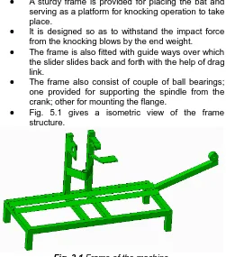
A sturdy frame is provided for placing the bat and serving as a platform for knocking operation to take place.
It is designed so as to withstand the impact force from the knocking blows by the end weight.
The frame is also fitted with guide ways over which the slider slides back and forth with the help of drag link.
The frame also consist of couple of ball bearings; one provided for supporting the spindle from the crank; other for mounting the flange.
Fig. 5.1 gives a isometric view of the frame structure.
Fig. 3.1 Frame of the machine
3.1.2 Piston and End weight
Piston is the actual moving part of the machine that draws its reciprocating motion from the action of crank web and connecting rod.
End weight or mass is the one that makes direct contact with the bat and responsible for surface hardening.
This end weight is made up of wood so as to resemble a mallet.
Fig. 3.2 End Mass
3.1.3 Worm Gear Box
Worm gear box such as shown in Fig. 3.3 acts as a speed reducer which reduces the output speed from the motor.
The speed ratio of the motor is 60:1.
This gear box is made of aluminium casing.
Fig. 3.3 Worm Gear Box
3.1.4 Motor
An AC motor is any of a class of rotary electrical machines that converts direct current electrical energy into mechanical energy.
Nearly all types of AC motors have some internal mechanism, either electromechanical or electronic; to periodically change the direction of current flow in part of the motor.
Fig. 5.4 depicts the AC motor used with its terminals
The motor used in the project is a 1HP 25W 200rpm Single Phase Induction motor, which are generally used for industrial purposes.
It can be operated by plugging in onto the 230V socket.
Fig. 3.4 AC Motor
3.1.5 Sprocket Gear
A sprocket or sprocket-wheel is a profiled wheel with teeth, or cogs, that mesh with a chain, track or other perforated or indented material.
In the project, two sprocket gears are used to transmit the power from gear box to the bearing that moves the flange.
Fig. 3.5 Sprocket Gear
3.1.6 Chain Drive
Chain drive is a way of transmitting mechanical power from one place to another. It is often used to convey power to the wheels of a vehicle.
The power is conveyed by a roller chain, known as the drive chain or transmission chain, passing over a sprocket gear, with the teeth of the gear meshing with the holes in the links of the chain.
The Chain drive with the sprocket is shown in Fig. 5.6.
The sprocket is turned, and this pulls the chain putting mechanical force into the system.
The pitch of the chain selected is 12.7mm and length of the chain is 1397mm.
Fig. 3.6 Chain drive connecting sprockets
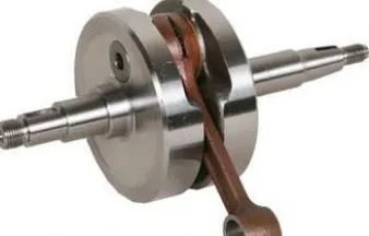
3.1.7 Crank and Connecting rod
To transfer the rotary motion of the electric motor into reciprocating motion for knocking operation, this setup of crank and connecting rod is used. This combination of crank and connecting rod was
taken from TVS XL moped as it was dimensionally suitable for the machine.
Fig. 3.7 Crank Web and Connecting Rod
3.1.8 Flange and Drag link
The flange is nothing but a replacement for crank in a slider crank mechanism and has several holes
in it to occupy the drag link’s mount for slider displacement adjustment.
The flange rotates by a ball bearing that draws power from the worm gear box via chain link. The drag link is more like a connecting rod that
connects the flange with the slider and responsible for the sliding action.
The length of the flange is 200mm and that of drag link is 342mm.
Fig. 3.8 Flange and Drag Link
3.1.8 Slider
Slider is more or less like a vice for holding the bat during the knocking process.
The slider slides over the guide ways that is made onto the frame and is operated by flange and the drag link.
Lubrication is provided for a smooth and noiseless operation.
Fig. 3.9 Slider
3.1.8 Spring
A compression spring is installed on top of the end mass, inside the hollow piston.
As the surface of the bat is uneven and curved, the spring is employed to compensate the gaps that arise while knocking the middle part of the curve. It also eliminates the thrust caused by pre-loading
the end mass, thus saving the bat from indent marks.
Fig. 3.10 spring
3.2 Material Selection
3121 The material selection is made by taking into account the
economical factors and standardization available.
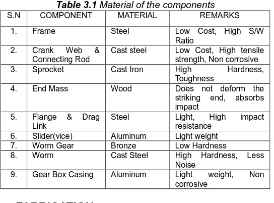
Table 3.1 Material of the components
S.N COMPONENT MATERIAL REMARKS
1. Frame Steel Low Cost, High S/W Ratio
2. Crank Web & Connecting Rod
Cast steel Low Cost, High tensile strength, Non corrosive 3. Sprocket Cast Iron High Hardness,
Toughness
4. End Mass Wood Does not deform the striking end, absorbs impact
5. Flange & Drag Link
Steel Light, High impact resistance
6. Slider(vice) Aluminum Light weight 7. Worm Gear Bronze Low Hardness
8. Worm Cast Steel High Hardness, Less Noise
9. Gear Box Casing Aluminum Light weight, Non corrosive
4
FABRICATION
4.1 Fabrication Process
The fabrication process involves various joining processes, primarily welding, fastening, bolting etc, to bring about a rigid structure.
4.1.1 Frame
The frame is the first fabricated component as seen in Fig. 3.1.
Mild steel was used to form the structure.
Two shapes of the mild steel were primarily used, a Circular channel (for the leg of the fame) and an L-Section channel (for the body of the frame). The channels were cut to the required height and
welded together.
Two bearing housings were provided on the frame and ball bearings were later tight fitted into the housings.
The L- Section channels were laid upside down and welded to resemble as guide ways.
A circular pipe was cut and welded across the main column to act as a support for the piston.
A platform for holding the gear box was also provided with bolting holes.
4.1.2 Piston and End weights
The piston was made of a hollow steel pipe that has mounting (to be pin joined to the connecting rod) at one end and opening at the other end as shown in Fig. 3.2 in the previous chapter.
The piston moves inside a cylinder that was welded to the frame with the help of steel plates.
The end weight was made from a single wooden piece.
The wooden piece was cut to the desired size and was turned and phased using a wood working lathe.
The end mass was inserted into the end of the piston by Morse taper mechanism; the end mass
can travel up and down but doesn’t completely fall from it.
4.1.3 Worm Gear box
A readymade worm gear box as shown in Fig. 3.3 was installed to use in the bat knocking machine. The gear box was mounted directly onto the frame
with the help of fasteners.
4.1.4 Motor
The Single phase AC motor with reference to the Fig. 3.4 is the prime mover of the machine. It was mounted safely over the provision plate
provided along the main column of the frame with the help of bolt and nuts.
The terminals of the motor were plugged into the main power source which in turn runs the system. The output of the motor was connected directly to the worm gear box after powering the crank web. The spindle of the motor was connected to the
crank web by screwing.
4.1.5 Sprocket and Chain
Two sprockets were installed in the machine and a readymade chain was used to connect them. One was mounted on the output end of the gear
box whereas the other was mounted to the ball bearing that turns the flange.
4.1.6 Crank and Connecting rod
The combination of crank and connecting rod was taken from TVS XL moped as shown in Fig. 3.7 and it was dimensionally suitable for the machine. The ends of the crank web were connected to the
spindles of electric motor and worm gear box respectively.
To damp the shocks and vibrations caused by this system, a ball bearing was employed within the frame.
4.1.7 Flange and Drag link
The flange was fabricated by cutting a 3mm steel plate into a rectangular piece and slots were made throughout the length for adjusting the slider displacement over the guide ways. The flange and drag link assembly can be seen in Fig. 3.8.
The free end of the flange was connected to the bearing bore by a spindle piece that was welded to the flange’s surface.
The drag link is made of a straight rod whose ends are fitted with rod end bearings to relax the movements caused by thrust.
One end of the link is pin joined to the flange while the other end is joined to the slider using fasteners.
4.1.8 Slider
The slider was made by laying two L-Section channel adjacent to each other and welding it with a metal plate to hold its position as shown in Fig. 3.9.
The other end of the slider was provided with a mount to be pin jointed to the drag link.
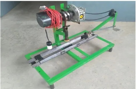
4.2 Fabricated model
Following are the images of fabricated model of bat knocking machine in three different views; isometric view, side view and front view respectively.
Fig. 6.1 Isometric View of the Fabricated Model
Fig. 6.2 Side View of the Fabricated Model
Fig. 6.3 Front View of the Fabricated Model
5
DESIGN
CALCULATION
5.1 Worm Gear Calculations GIVEN DATA:
Number of start = 1
Number of teeth on wheel = 60 Input speed n1 = 100rpm
Table 5.1 Results of Calculation of Worm Gear
Speed ratio = 60:1
i = i =
i = 60
STEP1: MATERIAL SELECTION FOR WORM AND WORM WHEEL
For worm: harden steel For worm wheel: bronze [𝜎𝑐] = 900kgf/cm^2 [𝜎𝑏] = 1590kgf/cm^2
STEP2: CALCULATION OF MINIMUM CENTRE DISTANCE
A ≥ ( + 1) √( ]) ] [Mt] = Mt. Kd. K Mt = 97420* * i* n
= 97420* ^
* 60* 0.75 Mt: = 1095.97 kgf.cm
A = (
+ 1) √(
) 1095.97
A = 10.39cm
STEP3: CALULATE OF MINIMUM AXIAL MODULE
mx = 1.24√ ] ]
mx = 1.24√ . ] . = 0.1929cm
Standard value of Mx = 0.2
STEP4: CALCULATION OF CORRECTED CENTRE DISTANCE:
A = 0.5 mx (q+ ƶ+ 2𝑥) A = 0.5*0.2*(11+60+0) A = 7.1cm
Increase m value=1; Therefore A=35.5cm STEP5: SLIDING VELOCITY
Sliding velocity = v
𝑣
= . V1 = 0.57𝑚 𝑠⁄
D = q* mx D = 11* 1 D = 11cm Vs = .
. = 0.57 𝑚 𝑠⁄
STEP6: CALCULATION OF FACE WIDTH Z = 1
S.NO PARAMETERS VALUE
1. CENTRE DISTANCE 355mm
2. MODULE 1mm
3. SLIDING VELOCITY 0.57m/s
4. FACE WIDTH 82.5mm
3123 B = 0.75*𝑑
= 0.75*11 = 8.25cm
STEP7: LENGTH OF WORM L = (11+ 0.06ƶ)* mx = (11+ 0.06(60))* 1 =14.6cm
5.2 Chain Drive Calculations Number of teeth on gear = 25 Number of teeth on pinion = 25 Centre distance = 535mm Speed = 1.66rpm
STEP1: CALCULATION OF SPEED RATIO i =
= i = 1
STEP2: CALCULATION OF STANDARD PITCH A = (30 to50) p
Pmin = =
= 10.7mm Pmax =
=
= 17.83mm
P IS IN THE RANGE FROM 10.7 TO 17.83 P = 12.7
STEP3: CALCULATION OF BREAKING LOAD N = .
N = 25* 10 KW
Table 5.2 Results of Calculation of Chain
V =
= . .
p
= 8.78*10 𝑚 𝑠⁄ N - Factor of safety
N = 7 for around 100rpm speed Ks = k1* k2* k3* k4* k5* k6 k1 = 1 (constant load factor) k2 = 1 (adjustable support) k3 = 1 [a(3o to 50)] k4 = 1 (horizontal drive) k5 = 1 (drop lubrication) k6 = (8hoursrun time) ks = 1
N = .
25*10 = . Q = 2033.02Kgf
STEP4: SELECT OF CHAIN
WE SELECT 08B-3 R-1278H FOR ∅ = 12.7 [Q] > 2033.32Kgs
Roller diameter = 8.51mm Width = 8mm
Bearing area = 0.54𝑐𝑚 Wt1m = 0.75Kgf Bearing load = 2100Kgf STEP5: ACTUAL SAFTY [n] =
Pt =
= .
Pt = 290.43Kgf
Pc =
= . ( . ) . =5.89*10 Kgf
TENSION DUE TO SAGGING PS = K* W * A
K = 6 W = 0.75Kgf A = 535mm Ps = 2.40Kgf [n] =
[n] =
. = 7.17Kgf
STEP6: CHECKING FOR BEARING STRESS POWER N =
IN KW
[𝛿] = 3.14𝐾𝑔𝑓/𝑚𝑚
STEP7: CACULATE LENGTH OF CHAIN LP = 2ap+ +(
)
Ap = = . = 42.12
Lp = 2* 42.12+ + (0) Lp = 110
L = lp* p = 110*12.7 = 1397mm
5.3 Impact force of Piston GIVEN DATA:
Motor Power = 1 HP 25W Motor Speed = 100rpm Length of Crank = 35mm
Length of Connecting rod = 80mm α = 11.3°
STEP1: TORQUE OF MOTOR T =
= = 71.61 Nm
STEP2: FORCE ON CRANK ROD FTC =
= . . = 1790.25 N
STEP3: FORCE ON CONNECTING ROD
S.NO PARAMETERS VALUE
1. STANDARD PITCH 12.7mm
2. BREAKING LOAD 2033.02kgf 3. BEARING STRESS 3.14kgf/mm2
4. CHAIN LENGTH 1397mm
FQ = FTC * cosα
= 1790.25 * cos11.3 = 536.61 N
STEP4: FORCE ON PISTON FS = FQ * cosα
= 536.61 * cos11.3 = 160.84 N
Hence, a force of about 160 N acts on the bat during the knocking process, which is optimal and matches with the force produced by a human hand during manual knocking process.
6 SYSTEM
IMPLEMENTATION
After successful fabrication of the machine, it was put to testing for performance evaluation. The implementation was done in a controlled environment. The machine was
turned on and a junior bat was placed on the slider. The end mass contacted the surface of the bat perfectly with the desired force. We continuously operated the machine for about 30 minutes to check the stability and reliability of the setup and also to check the quality and clarity of the work obtained.
6.1 Deviation from Design
The only deviation from design on the machine was the worm gear box. Due to the unavailability of gear box with a speed ratio of 100:1, we ended up purchasing one with 30:1 gear box. It had no adverse effect on the performance of the machine, except that the slider moved back and forth too quickly than expected.
7 CONCLUSION
AND
FUTURE
SCOPE
7.1 Conclusion
The limitations of manual knocking and sophisticated knocking machines are rectified by the development of this machine. The man-hour is highly reduced and the effectiveness and productivity of the knocking process is increased. The slider crank mechanism plays a key role in the generation of work and impact forces. The chain and sprockets play a vital role as transmission systems. The continuous and periodic knocking of end mass can aid in a smoother and evenly distributed knocking on the bat’s surface. Hence, compactness and cost effectiveness of the machine is achieved.
7.2 Future Scope
On looking into the existing products, we have decided to include the following features in near future which are useful and at the same time spare less money from the pocket,
Automatic Knocking mechanism with replaceable end masses.
Digital Counter to track the number of knocks.
Alarm to intimate the completion of Knockingprocess.
Speed control of the electric motor to adjust the pressure setting of end masses.As the knocking process looks similar to a punching process, this machine can be modified to act as a power hammer for forging operation or a punching press for punching operation. Hence multi utility of the machine is achieved.
8 REFERENCES
[1] Eftaxiopoulou, T., et al. (2012). "A performance comparison between cricket bat designs." Proceedings of the Institution of Mechanical Engineers, Part P: Journal of Sports Engineering and Technology 226(1): 16-23.
[2] Fisher, S. (2005). Experimental and finite element analysis of cricket bats, University of Bath (United Kingdom).
[3] Sabu, J. and Z. Li (2002). "Multi-directional vibration analysis of cricket bats." RMIT University.
[4] Sayers, A., et al. (2005). "Surface hardness of a cricket bat after ‘knock-in’." Sports Engineering 8(4): 233-240. [5] Singh, H. and L. Smith (2008). Describing the
Performance of Cricket Bats and Balls. Washington State University Conference, Citeseer.