R E S E A R C H
Open Access
Self-organising interference coordination in
optical wireless networks
Birendra Ghimire
1*and Harald Haas
1,2Abstract
In this article, self-organising interference management for optical wireless networks deployed inside an aircraft cabin is investigated. A user that has received data in a given frame and intends to continue receiving data in the next frame broadcasts a busy burst (BB) in a time-multiplexed BB slot. The tagged access point (AP) intending to reuse a resource reserved in a neighbouring cell must listen to the BB slot. Provided that channel reciprocity holds, the tagged AP infers (prior to transmission) the amount of co-channel interference (CCI) potentially caused towards the victim user in neighbouring cell. This is a vital information for an AP to decide without any central supervision whether to transmit or defer the transmission to another time or frequency slot so as to limit CCI caused to the active link to a threshold value. Simulation results demonstrate that the BB approach significantly improves both fairness and spectral efficiency in the system compared to a static resource partitioning approach.
1. Introduction
Data transmission using optical wireless has been identi-fied as a technology that can be utilised for communica-tions in critical environments, such as aircrafts or hospitals, where radio frequency (RF)-based transmis-sions are usually prohibited or refrained to avoid inter-ference with critical systems. Moreover, a huge amount of unregulated bandwidth is available at infra-red and visible light frequencies. Likewise, optical wireless signals can be confined within a room which inherently addresses concerns over the eavesdropping of data. In addition, commercially available light emitting diodes (LEDs) and photodiodes (PDs) can be utilised for data transmission and reception. Therefore, there has been a considerable interest in utilising the frequencies at the infra-red and visible spectrum for data transmission [1-7].
The state-of-the-art technique [7] that utilises on-off keying (OOK) for transmitting data using visible light is rather inflexible when it comes to sharing bandwidth among multiple competing users served by an AP that have variable rate requirements. The above shortcoming is addressed by utilising optical intensity modulation (IM)/direct detection (DD) orthogonal frequency
division multiplexing (OFDM) for data communication. Using OFDM technique [8,9], the available bandwidth can be shared among multiple users by assigning each user a different amount of bandwidth corresponding to the user demand and the scheduling policies. Likewise, link adaptation can be carried out to scale the user throughput according to the prevalent channel condi-tions at the receiver. The composite baseband signal is modulated onto the optical carrier by varying the optical power proportional to the baseband signal amplitude in an optical IM/DD system. The fluctuation in instanta-neous optical power is detected by a PD, which converts the received optical signal to an electrical signal, which can be decoded by the receiver. Even if LEDs that radi-ate in the visible light spectrum are used, the fluctua-tions in optical power are imperceptible to human eye but can be easily detected by a PD. As such, the LEDs can be used simultaneously for both lighting and data transmission.
Although the overall bandwidth in the visible or infra-red spectrum is in the tetrahertz (THz) range, the band-width of the signal that can be utilised by an optical IM/DD system using LEDs is inherently limited by the bandwidths of transmitter and receiver frontends. In order to serve multiple users and have ubiquitous sys-tem coverage, it becomes necessary to reuse the avail-able bandwidth. Although bandwidth reuse potentially increases the system capacity, transmission of data * Correspondence: [email protected]
1
School of Engineering and Science, Jacobs University Bremen, 28759, Bremen, Germany
Full list of author information is available at the end of the article
intended for a user inevitably causes interference towards other users receiving data on the same resource and vice versa. An orthogonal frequency division multi-ple access (OFDMA) network where the chunks (time-frequency slots) are fully reused is prone to high CCI at cell-edge. This potentially causes a significant reduction of user throughout and causes outage at the cell-edge in the worst case. Therefore, interference coordination is essential among multiple optical cells within the net-work in order to balance system capacity against enhanced throughput at the cell-edge.
To achieve the aforesaid goal, several interference coordination mechanisms have been investigated in the literature. Static resource partitioning [10,11] using tra-ditional cluster based frequency planning approach is the most commonly used approach. With this approach, the users served by a tagged AP are restricted to use a certain fixed subset of the available chunks in the sys-tem. CCI is mitigated by ensuring that any two cells that reuse the same set of chunks are separated in space by a minimum reuse distance. The shortcoming of such approach is that it can cause some of the chunks to remain idle even though transmitting data on these chunks would not cause detrimental CCI towards other users in the neighbouring cells. Furthermore, if the instantaneous traffic loads varies widely among cells within the network [12], such approach can lead to wastage of resource in lightly loaded cells and fail to cater for the traffic demands in heavily loaded cells. The available system bandwidth and consequently the share of bandwidth per user can be enhanced by using the principle of wavelength division multiplexing (WDM) [13] such that a tagged cell can use one of the three pri-mary colours,i.e. red, green and blue, for data transmis-sion which retains the advantage of the frequency planning approach and at the same time enhances the system bandwidth. However, such approach adds to the cost of receiver unit because separate filters and PD with peak spectral response for each colour band are required.
An entirely different approach to enhance system capacity and link throughput is to use imaging techni-ques, which can separate the optical signals impinging from different sources [14,15]. The optical signals from two different sources would excite different regions of an imaging concentrator. As such, the data from differ-ent streams can be selected or rejected independdiffer-ently. However, such approach would reduce the effective receiver area for the intended signal and therefore require longer integration time for signal detection. Furthermore, the cost of the imaging concentrators would be significantly higher than a standard PD used in optical receivers. Hence, in order to enhance band-width reuse and mitigate interference in a cost-effective
manner, spectrum sensing approaches would be needed. To this end, the classical carrier sense multiple access (CSMA)/collision detection (CD) approach is considered for optical wireless applications [16]. However, it is well known that the CSMA/CD approach suffers from hid-den node and exposed node problems, both of which degrade the performance in an wireless network.
To address the above shortcomings, interference aware allocation of time-frequency slots (chunks) using BB signalling for transmitting data in optical IM/DD-based OFDMA-time division duplex (TDD) systems is considered in this article. With the proposed approach, the assignment of chunks in a tagged AP is adjusted dynamically depending on the location of an active user in the neighboring cell. To facilitate this, each user equipment (UE) must broadcast a BB [17,18] in a time-multiplexed slot after successfully receiving data in order to reserve the chunk for the next frame. The AP that intends to transmit on a given chunk must listen to the BB slot corresponding to that chunk. Provided that TDD channel reciprocity [19] holds, the AP infers the amount of CCI it could potentially cause towards the user that has reserved the chunk. This is vital informa-tion that allows an AP to decide without any central supervision whether to transmit or defer the transmis-sion to another time and/or frequency slot so as to limit the CCI caused to the active link to a threshold value. The impact of this threshold parameter on the perfor-mance of optical OFDMA networks deployed in a cabin of an aircraft is investigated. Extensive system level simulations demonstrate that performing chunk alloca-tion using the BB protocol enhances the mean system throughput by 17%, whilst maintaining the same throughput at the cell-edge compared to that achieved with static resource partitioning. In addition, it is found that when the offered load begins to exceed the traffic capacity, hardly any chunks available for a tagged AP are idle. As a result, a new user entering the network or an existing user switching from idle (empty buffer) to active (with a packet in the buffer) state would suffer outage. A heuristic that annuls reservation after a user has had its fair share of resources is proposed. Simula-tion results show that the BB protocol combined with the proposed heuristic significantly improves both the guaranteed user throughput and the median system throughput compared to the static chunk allocation using cluster-based resource partitioning.
2. System model
An optical wireless network whereUusers are served by
NA optical APs is considered for the downlink mode.
The transceiver module consists of an array of LEDs and a PD for transmitting and receiving optical signals respectively. An OFDMA-TDD air interface is consid-ered, where the available system bandwidthBis divided intoNscsubcarriers.
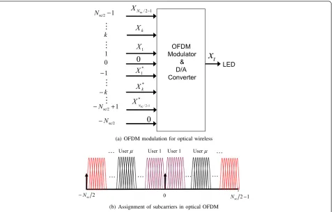
The baseband symbols are modulated into an OFDM symbol using inverse discrete Fourier transform (IDFT) and converted into analog signal by digital to analog (D/ A) converter. The LED transmits an optical signal whose intensity is directly proportional to the driving current (i.e. IDFT output). The analog signal transmitted by the LED is given by
xt =ρ 1 NSC
Nsc/2−1
k=−Nsc/2
Xke−j2πk B
NSCt, (1)
wherextis the instantaneous intensity of optical signal emitted by LED at time instant t;ris the scaling factor that maps the IDFT output to analog optical signal;Xk is the data symbol transmitted on subcarrierk, which is taken from a normalised symbol constellation such that Var{Xk} = 1 W. The total signal power transmitted per subcarrier is P2opt/Nsc, wherePopt is the standard
devia-tion ofxt. Hence, the scaling factorris set to P2opt/Nsc.
In general, the IDFT operation results in complex num-bers. However, the optical output is constrained to real and positive numbers. Therefore, X-k is set to X−∗k as depicted in Figure 1a, X-Nsc/2 is set to 0 and x0 is set
such that clipping of the OFDM signal is avoided. The above restriction limits the number of chunks that can be independently allocated to half of what is available within the system bandwidth. The transmitted signalxt
propagates through the wireless channel and impinges upon the PD at the receiver. The overall channel gain between the LED and the PD is denoted byG, which is expressed as [11]
G= (m+ 1)
2π cos
m(φ)gplA
pdTψsgcψcos(ψ), (2)
where m is the mode number of the radiation lobe
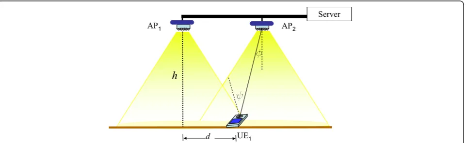
given by - ln 2/ln(codF), whereFis the angle at which the radiated power reduces to half compared to the power radiated along the normal of the plane containing the LED; the anglesjandψare as depicted in Figure 2;
gpl is the optical path loss between the LED and PD
which models the propagation of optical signal in space;
Apd is the area of the PD; Ts
ψ models the signal trans-mission through the optical filter at the PD and gc
ψ is the concentrator gain of a non-imaging concentrator.
The received (optical) signal is converted into an elec-trical current by a PD whose responsitivity isRpd. The current signal is converted into voltage signal by a tran-simpedance amplifier (TIA) whose gain is RF. The elec-trical signal at the TIA output is expressed as
Yt=RF(RpdGxt+t), (3)
where Ωt is the additive white Gaussian noise
(AWGN) noise which is dominated by shot noise of the PD and the thermal noise of the resistor of the TIA. The received signal is sampled, quantised and passed through fast Fourier transform (FFT) block. Assuming that the D/A and analog to digital (A/D) converters are time and frequency synchronised, the output of the dis-crete Fourier transform (DFT) operation is given by
Yk=RF(RpdGXk+k), (4)
Server
h
d
AP1 AP2
UE1
whereΩkis the noise observed on subcarrierk, whose ent light incident on the PD;kBis the Boltzmann’s
con-stant; T is the absolute temperature and Bsc is the
bandwidth of a subcarrier. In this article, clipping noise [9] and noise due to the non-linear transfer function of the LED [20] are ignored as these parameters are not central to the contributions of this article.
3. Interference coordination in optical cells
A simplified model of the optical wireless cellular sys-tem considered in this article is depicted in Figure 2. The available OFDMA subcarriers are grouped in
con-tiguous blocks made up of nsc subcarriers and nos
OFDM symbols. Such blocks form a resource unit called achunk and is denoted (k, n) where kis the frequency index and nis the time index. Letμdenote a UE which is associated with an AP a. Likewise, UE ν is another
UE which is served by AP b, where b ≠ a using the
same chunk that is used by APato serve UEμ.
There-fore, AP acauses CCI to UEν and AP bcauses CCI to
UEμ.
In order to distinguish between the intended and the interfering signals, the channel gains (2) are distin-guished by adding subscripts of the form Ga,μ where
the first subscript denotes the transmitter and the sec-ond one denotes the receiver. Likewise, a transmitter index is added to the transmitted symbol to distinguish the symbols transmitted by different transmitters. To this end, Xa is used to denote the symbol transmitted
by transmitter a. The subcarrier indices are omitted for clarity, since the equations apply to an arbitrary
chunk in the system. From the perspective of UE μ,
the desired and interfering signal power can be expressed as
Rdμ= E[|Ydes|2] = E[|RFRpdGα,μXα|2] (6)
Iμd= E[|Yinf|2] = E[|RFRpdGβ,μXβ|2]. (7)
Since the subcarriers are assigned in chunks, the sig-nal-to-interference-plus-noise ratio (SINR) is constant
…
(a) OFDM modulation for optical wireless
0
(b) Assignment of subcarriers in optical OFDM
Figure 2Depiction of interference in optical wireless network for the downlink. AP1is the intended transmitter for the receiver labeled
for all subcarriers within the chunk. The SINR at UEμ on chunk (, n) is expressed as
γμ[κ, n] = R
d
μ[κ,n] Id
μ[κ,n] +N
= (RpdGα,μ[κ,n]ρ)
2
(RpdGβ,μ[κ,n]ρ)2+N ,
(8)
where it is assumed that the transmit power (electri-cal) on each subcarrier isr2.
The received signal must be received with a certain minimum SINR that corresponds to the modulation and coding format used for transmission to decode the received signal with a bit error ratio (BER) lower than a tolerated limit. The maximum tolerable BER figure depends on the application and in general it is consid-ered to be 10-3for voice and 10-7for data. The trans-mitter and receiver pair can communicate with each other as long as the minimum SINR target needed for decoding the lowest order modulation and coding scheme with the required quality of service (QoS) is met. To enable the SINR target to be met, the allocation of resources among the links closely located in space needs to be coordinated. One means to coordinate the resources in a self-organising and decentralised manner is to apply the BB protocol for interference aware resource allocation in the system.
Interference coordination using BB signalling com-prises of the following key components, namely
(1) Interference avoidance: The transmitter avoids causing detrimental CCI towards the receivers of pre-established links. This is achieved by sensing the BB sig-nal to determine the idle chunks as described in Section 3.1.
(2) Contention mitigation: The access of chunks that are not yet reserved by transmitting a BB signal is regu-lated such that at most one transmitter within a coordi-nation cluster may access the idle chunks. Such coordination is required so as to ensure that no two transmitter sense the same chunk as idle and cause col-lision of data in the next frame. This procedure is described in Section 3.2.
(3) Interference aware scheduling: The transmitter does not schedule transmissions for a user on the chunks where the receiver senses high level of CCI ori-ginating from pre-established links, even if the trans-mitter has sensed the chunk to be idle. In a multi-user cellular system, such as the one considered in this arti-cle, the chunk can be reused at the tagged AP by allo-cating it to a different user that reports a lower level of a prioriCCI. This procedure is described in Section 3.4.
3.1. Interference coordination using BB signalling
For interference coordination among optical wireless cells, the medium access control (MAC) frame is divided into data and BB slots. Data transmission is carried out during the data slot and the BB is transmitted during the BB mini slot. Each receiver must transmit a BB to announce its presence to other APs so that they may autonomously determine whether or not they can reuse the reserved chunk. To this end, it is assumed that UE
μ has transmitted a BB after receiving data during its
data slot. The busy burst signal transmitted by UE μ
propagates through the optical channel and is received both at APsaandb. The received signal at the serving
APa informs the transmitter that the minimum SINR
target has been met. Furthermore, additional informa-tion can be piggybacked to the BB signal for feedback and control purposes. By contrast, the received BB
sig-nal at AP b makes it aware of the amount of CCI it
potentially causes to the active receiver μif it were to reuse the reserved resource. By measuring the signal
power received during the BB slot, the AP b decides
autonomously whether or not it may reuse the reserved chunk so as to limit the interference to a threshold value. To this end, the received BB signal at AP bcan be written as
ybbk =RFRpdGμ,βxbbk,β. (9)
The power of the BB signal is given by
Ibbβ = E[|ybbk |2] = (RFRpdGμ,βρbb)2. (10)
Combining (7) and (10) and provided that
Gβ,μ=Gμ,β,Idμ can be expressed in terms of Ibbβ as
Id
μ=
ρ ρbb
2
Ibb
β . (11)
The condition Gb,μ =Gμ,b holds true if eitherm= 1,
which is the case for Lambertian transmitters (j= 60°) or if j= ψ, which is true when the transmitter plane and the receiver plane are parallel to each other.
Ifr=rbb, from (10) and (11),
Id
μ=Ibbβ . (12)
To ensure that Id
μ ≤Ith APbmay reuse the resource
if Id
μ≤Ith. Furthermore, provided that both the transmit
data power and the BB power (in electrical domain) are equal, the condition for reusing a resource is given by
Hence, by measuring the BB power observed during
the feedback slot, AP b determines whether or not it
causes detrimental CCI (i.e. CCI higher than the
prede-termined threshold value) towards the active user μ
served in an adjacent cell a. For a given thresholdIth, (13) is more likely to hold true ifμ lies close to AP a compared to the case if μ lies at the boundary of the
coverage regions of APs a and b. Therefore, each AP
can dynamically determine the set of chunks it can use for transmission whilst avoiding detrimental CCI to pre-established links simply by measuring the received BB power and comparing it against the threshold value and without requiring a central coordinator.
The BB protocol relies on the assumption that AP a
and APbdo not check (13) simultaneously. If both AP
a and APb were to sense the channel simultaneously,
they would both infer that the channel is free, since there is no pre-established receiver in the vicinity that announces its presence by emitting a BB signal. In such scenario, they would both schedule transmission for their own users without any knowledge of the user the other AP might schedule. Hence, each of the APs can potentially cause severe CCI to the user served by the other AP. Such collision can potentially cause high out-age particularly at the cell-edge. To mitigate such pro-blem, the cellular slot access and reservation (CESAR) approach [21] is used, which ensures that an idle chunk is not assigned simultaneously by neighbouring APs through a cyclic shifted allocation pattern for idle chunks.
3.2. Contention avoidance among neighbouring cells The contention problem can be mitigated by exploiting the properties of a cellular network using CESAR approach proposed in our earlier study [21]. In sum-mary, the available chunks within the system bandwidth
are grouped into R different subbands. Likewise, the
cells in the system are also grouped into R different groups G, such that the APs within a coordination clus-ter belong to different groups. For the optical network, a reasonable choice of the group size is R= 3. At time instant n, the APsb that belong to group gβ[κ,n]∈G may accessidlechunk (, n) in a predefined cyclic man-ner, determined by [21]
gβ[κ, n] = mod (n+κ, R). (14)
The term gβ[κ,n]∈G determines whether or not a
chunk (, n) may be accessed by AP b. Hence, (14)
establishes a schedule to accessidlechunks,i.e. chunks that are not protected by transmitting the BB. Thus, the CESAR mechanism ensures that at a particular time
instant k only one group of APs may access idle
resources, thereby mitigating the contention problem.
Cyclicly shifting the AP groups in (14) over time ensures that after Rslots an AP is granted access to all chunk that are sensed idle. The APs are numbered such that an AP is associated to its group by the relation G={mod(β,R)}. Then, the APb may allocate chunk (, n) to userν only if both of the following conditions hold:
(1) mod(b, R) = mod(n + k, R) indicates that AP b may access chunk (, n).
(2) The threshold test (13) applied on chunk (, n) holds true.
The second condition indicates that chunks already reserved by transmission of a BB signal retain unrest-ricted access to a given frequency resource unitk, and continue to serve the users that have reserved those chunks. CESAR [21] and BB protocol for interference coordination in optical wireless network perfectly com-plement each other; the former mitigates collisions due to simultaneous access in contention through (14), while the latter facilitates interference aware selection of chunks reserved by transmitting the BB signal.
3.3. Avoiding CCI from preestablished links
The mechanism discussed earlier focussed on how an AP can determine the set of chunks that it is permitted to use so as to limit the CCI caused to users served by the neighbouring APs to a threshold value. However, UE νalso suffers from CCI originating from pre-estab-lished links, which make no effort to limit the CCI caused to the newly entering link. Hence, the minimum SINR target may not be met for the cell-edge user served by the tagged AP if the user is served using the chunks that are in use in the neighbouring cell. To
avoid scheduling UE ν on a chunk where the CCI
caused by pre-established communication links would
cause the minimum SINR target not to be met, an a
prioriestimate of SINR γνˆ [κ, n] is made as follows
ˆ
γν[κ, n] = R
d
ν[κ,n] Id
ν[κ,n−1] +N
, (15)
where Idν[κ, n−1] is the interference observed on the chunk (, n -1). To ensure that the collisions are miti-gated, the chunk can be assigned to userν only if
ˆ
γν[κ, n]≥min. (16)
This information can be transmitted to the serving AP either using piggyback signalling or via dedicated con-trol channel.
3.4. User scheduling
AP. The users compete for being scheduled on chunks that are not yet reserved for any user served by a given AP. Numerical scores are calculated for each user on each chunk which serves as a quantitative basis for ranking each user’s suitability for being scheduled on each chunk. The user that is scheduled on chunk (, n)
set depending on the SINR achieved at the receiver dur-ing the data transmission slot, as follows
bν[κ, n] =
1,γν[κ, n]≥minandζβ[κ, n] =ν
0, otherwise (18)
where bν [, n] = 1 indicates that the user ν has reserved the chunk (, n+1) by transmission of BB dur-ing the BB mini slot associated to chunk (, n). For these reserved chunks, the modulation format is updated using the link adaptation algorithm proposed in Section 3.5. All users served by the tagged AP compete for getting access to the idle chunks in the system. The score for each user sν,b on each chunk is calculated by taking instantaneous fairness in the system and by respecting any restriction imposed on accessing the chunk. The score to be used in (17) for userν served by APbfor chunk (, n) is calculated as
sν,β[κ, n] =ν,β[κ, n] +ν, (19)
where the term εν,bÎ{0,∞} indicates whether an idle chunk (, n) (i.e. bν [, n-1] = 0 in (17)) may be
accessed by userν, given by
εν,β[κ,n+1]→0,Ib
β[κ,n]≤Ith and mod (β,R) = mod (κ+n+ 1,R) and γˆν[κ,n]≥min
∞, otherwise. (20)
In (20), the first relation evaluates the threshold test (13) for interference aware beam selection; the second relation determines if the APbis granted access to idle
chunk (, n + 1), according to the CESAR principle
described in Section 3.2; whereas the third relation ascertains that the estimated SINR at the receiver exceeds the minimum SINR target to avoid interference from preestablished links to the tagged link. Ifεν,b[, n
+ 1]®∞is set for allUSusers, the chunk remains idle in sectorb, so thatζb[, n+ 1] =∅in (17).
Likewise, the term Ψνis a priority penalty factor for userν. Each user is assigned the chunk which the afore-said user had reserved by transmitting a BB. The penalty factor ensures that the users that have fewer chunks already reserved have higher priority in accessing idle chunks. To this end,Ψνis initialized at the start of the scheduling process, as follows
ν = exp
is updated, as follows
ν←νexp(1), (22)
so that the users that have fewer chunks already assigned are preferred to be scheduled on subsequent slots.
In the scheduler considered above, the chunks are reserved by a user by transmitting a BB as long as it has data to transmit. If the user that has successfully accessed the chunk has no more data to transmit, the reservation is annulled and the chunk may be reas-signed to another user. Unfortunately, the scheduler does not preempt any user with heavy traffic volume from reserving all the chunks within the system band-width. Thus, such users will cause a new user entering the network or a user switching from idle state (empty transmit buffer) to active state (at least a packet in the transmit buffer) to find that all the chunks in the net-work are busy, thereby causing high outage. To address such problem, a fair reservation mechanism is proposed where the reservation made by the user by transmitting a BB is annulled by the serving AP imme-diately after finding that the number of slots a chunk has been reserved by a user exceeds the reservation threshold. This is achieved by setting the reservation indicatorbν[, n] as follows
where Rthis the reservation threshold which is a user specific parameter. It is proposed that theRth parameter should be set to
Rth= expresses the number of chunks assigned to userν.
3.5. Link adaptation
Let M={1, . . ., M} be the set of supported modula-tion schemes. Associated to each modulamodula-tion scheme
mÎM is an SINR targetΓ = {Γ1,...,ΓM} that must be
holds. Assuming that the channel does not change sig-nificantly between two consecutive time frames, feed-back of SINR observed in the preceding frame is used to select appropriate modulation format for the next frame. It is sufficient to provide quantised feedback using⌈log2(M)⌉bits, where⌈(·)⌉is the ceiling operator.
Such quantised feedback may be piggybacked to the BB signal. Therefore, additional overhead involved in dedicating one OFDM symbol for accommodating the BB mini-slot is compensated by utilising the BB for signalling purposes. In order to determine a suitable modulation format, the following steps are carried out at the UE (except Step 3 which is carried out at the AP):
(1) Conduct an a priori estimate of the SINR on
chunk (, n) based on the interference measured in the preceding frame
(2) Determine the largest order modulation scheme,
ˆ
m, which fulfils γνˆ [κ, n]≥mˆ[κ,n] using a look up table
and feed back mˆ to the AP.
(3) Transmit data using mν[κ, n] =mˆ to the intended UE.
(4) Make an a posteriori estimate of the achieved
SINRgν[, n] using (9).
(5) Recalculate mˆ using the look up table, such that γν[κ, n]≥mˆ[κ, n] holds.
(6) Compute the modulation scheme to be used in the next frame as follows
mν[κ, n+ 1] = ⎧ ⎨ ⎩ ¯
m, γν[κ, n]≥mν[κ,n]+1
0, γν < min
mν[κ, n], otherwise,
(25)
Where m¯ =mν[κ, n] +m[ˆ κ, n])/2.
(7) If mν [, n+1] = 0, or the chunk is no longer
needed, do not transmit BB and release chunk (, n). Otherwise, transmit BB with mν[, n+1] piggybacked
and go to Step 3.
3.6. Benchmark system
Chunk allocation using static resource partitioning using the cluster-based approach [10,11] is considered as the benchmark. Kadjacent optical APs form a coordination cluster as depicted in Figure 3a and the available
band-width is divided equally among theK APs within the
cooperation cluster as depicted in Figure 3b. In this arti-cle, a cluster sizeK= 3 is chosen.
In addition, comparisons are also made against a full chunk reuse system where each AP transmits on the entire available bandwidth without interference coordi-nation among neighbouring cells.
1
2
3
1
1
2
2
3
3
(a) Depiction of a coordination cluster
Time slot
Freque
ncy
3
2
1
(b) Resource partitioning approach
Time slot
Freque
ncy
Time slot
Freque
ncy
Time slot
Freque
ncy
1
2
3
Idle slots Busy slots(c) Illustration of CESAR approach
4. Results and discussions
The performance of the chunk allocation mechanism using BB signalling is compared against the bench-mark systems discussed earlier in Section 3.6. The perfor-mance metrics considered are user throughput and sys-tem throughput, which is an aggregate throughput of all users served by a given AP.
4.1. Simulation setup
An optical wireless network deployed inside an aircraft cabin is considered where the APs (denoted by ‘+’) are distributed as depicted in Figure 4. The transmitter is an array of LEDs [22] and the receiver contains a single photodiode [23], both of which have peak spectral response at 850 nm. The components for transmitter and receiver are assumed to be identical both at the APs and the UEs.
Users are uniformly distributed in a plane surface at a height of 1 m from the plane containing the APs. The channels are modelled using the pathloss model reported in [11]. The channels are assumed to be fre-quency flat and time invariant, which is a reasonable
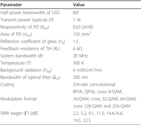
assumption because multipath components cannot be resolved due to the size of the detector area relative to the carrier wavelength. A full buffer traffic model is con-sidered and perfect synchronisation in time and fre-quency is assumed. Link adaptation is performed using the algorithm proposed in [24] where the available mod-ulation and coding format is matched according to the prevalent channel conditions at the receiver. The simu-lation parameters are presented in Table 1.
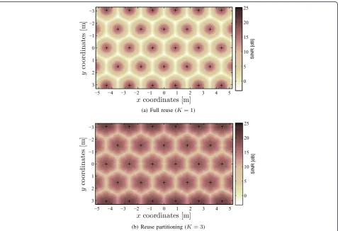
4.2. Distribution of SINR in space
The spatial distribution of SINR around each AP is depicted for the downlink (DL) mode in Figure 4. The results show that the SINRs fall as low as -3.2 dB on aver-age, given that all the available chunks are reused in each cell. However, when the allocation of chunks is coordi-nated using a static cluster-based resource partitioning approach, the SINR at the aforesaid location improve to roughly 8 dB. Clearly, the system is limited by interfer-ence rather than by noise for the set of system para-meters considered. Therefore, the goal is to balance the reuse of chunks with the SINR achieved at the receiver,
xcoordinates [m]
y
co
o
rdina
te
s
[m
]
−5 −4 −3 −2 −1 0 1 2 3 4 5
−3
−2
−1
0
1
2
3
SINR [dB]
0 5 10 15 20 25
(a) Full reuse (K= 1)
xcoordinates [m]
y
co
o
rdina
te
s
[m
]
−5 −4 −3 −2 −1 0 1 2 3 4 5
−3
−2
−1
0
1
2
3
SINR
[dB
]
0 5 10 15 20 25
(b) Reuse partitioning (K= 3)
such that a desirable compromise can be made between the conflicting goals of improving the system throughput and enhancing user throughput at the cell-edge.
4.3. Performance of BB signalling
In the following, the performance of BB signalling is compared against a cluster-based resource partitioning approach as well as against a full chunk reuse approach. For the results presented in this section, the chunk reservation policy is that a user that has transmitted a BB is assigned a chunk as long as it has additional data to transmit in its buffer.
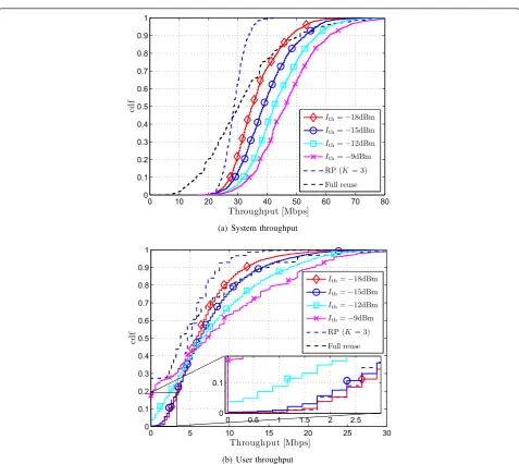
4.3.1. Full buffer traffic model
The performance of the BB protocol is compared against the benchmark system in Figure 5. The impact of the threshold parameter on the system performance is investigated using four representative values of the BB specific threshold parameter, namely -18, -15, -12, and -9 dBm. The results show that setting the threshold to -18 dBm enforces the largest exclusion region around the active receiver and therefore leads to highest guaran-teed user throughput (measured at 10th percentile of user throughput) among the considered thresholds and the benchmark systems. By setting the threshold to -18 dBm, a guaranteed user throughput of 1.97 Mbps is achieved (see Figure 5b). For comparison, the static fre-quency planning using a reuse factor 3 also achieves roughly the same cell-edge user throughput. This obser-vation demonstrates that a reuse factor of 3 is optimal for the considered system at the cell-edge since the throughput cannot be improved further by reducing or increasing the reuse of the chunks. Additionally, the interference awareness property of BB signalling mechanism helps the tagged AP identify the chunks that
are allocated to the cell-center users in the neighboring cells and reuses such chunks to serve its own user. Therefore, the BB protocol is able to improve the throughput of cell-center users (compared to the resource partitioning approach using reuse factor of 3) without compromising the cell-edge user throughput. As a result, the system throughput (see Figure 5a) improves by 17% using BB protocol compared to using cluster-based resource partitioning approach with a cluster size of 3.
When the threshold is gradually increased, the system throughput increases due to an increase in the spatial reuse of chunks but the throughput at the cell-edge decreases. Initially, the increase in CCI reduces the achieved SINR at the receiver and forces the transmit-ters to utilise lower order modulation and coding for-mat. However, on further increasing the threshold, the cell-edge users are forced to release the reserved chunks since the minimum SINR target is no longer met. The scheduler then assigns the released chunks to cell-center users where the minimum SINR target is more likely to be met. This is because the CCI caused to the receiver from pre-established transmission in neighboring cell causes the minimum SINR target (16) not to be met for the cell-edge users. As a result, the number of chunks allocated to users close to the serving AP increases at whereas the number of chunks available to the cell-edge users reduces. Hence, the system throughput increases (see Figure 5a) at the cost of cell-edge user throughput (see Figure 5b). In particular, when the interference pro-tection is annulled by setting high thresholds, such as -9 dBm, the performance at the cell-edge approaches that of a full reuse system (see Figure 5b). The released chunks are reallocated to cell-center users, which improves the system throughput at the cost of outage at the cell-edge. The results in Figure 5 depict the various degrees of trade off between interference protection and spatial reuse simply by adjusting the threshold parameter.
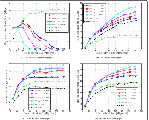
4.3.2. Bursty traffic model
The results in Section 4.3.1 were obtained assuming a full buffer traffic, which represents an upper limit on the offered load where each user has enough data to fill the entire bandwidth in every slot. For practical application such as accessing multimedia contents, user traffic is composed of Internet protocol (IP) pack-ets. An interesting question would be to quantify the performance of the proposed approach when the traffic is bursty. To investigate the performance, the system is simulated for various offered loads ranging from roughly 10 Mbps/cell to 160 Mbps/cell and the results are presented in Figure 6. The offered loads are varied by adjusting the interarrival time, which follows an exponential distribution. The results show that
Table 1 Simulation parameters
Parameter Value
Half power beamwidth of LED 60° Transmit power (optical) (P) 1 W Responsitivity of PD (Rpd) 0.63 [A/W]
Area of PD (Apd) 150 mm2
Reflection coefficient of glass (ng) 1.5
Feedback resistance of TIA (RF) 6 kΩ
System bandwidth (B) 20 MHz
Temperature (T) 300 K
Background radiation (Pbg) 6 mW/cm 2
/nm Bandwidth of optical filter (lof) 300 nm
Coding 3/4-rate convolutional
BPSK, QPSK, cross 8-QAM, Modulation format 16-QAM, cross 32-QAM, 64-QAM,
cross 128-QAM and 256-QAM SINR target (Γ) [dB] 2.2, 5.2, 9.1, 11.3, 14.4,16.6,
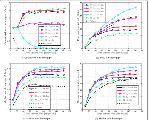
interference coordination improves the performance of the system compared to that achieved without interfer-ence coordination (i.e. full chunk reuse). Moreover, it can also be observed that dynamic chunk allocation using the BB protocol achieves better performance than that is achieved with the cluster-based static chunk allocation using a cluster size of 3 in terms of median system throughput, median user throughput and peak user throughput (See Figure 6b-d). This is attributed to the interference awareness property of the BB protocol that allows the system to identify the chunks that can be reused in the tagged cell without causing detrimental CCI to the users served by the neighbouring APs. However, an interesting behaviour can be observed with the guaranteed user throughput,
i.e. the 10th percentile (Figure 6a). When the offered system load is less than 25 Mbps/cell, the chunks in the system are not fully reused and therefore chunk allocation using BB approach provides the same throughput as the static chunk allocation approach. When the offered load is increased from 25 Mbps/cell to 40 Mbps/cell, dynamic chunk allocation using the BB protocol delivers a superior performance in terms of peak user throughput, median system throughput and median user throughput (see Figure 6b-d), whilst achieving the same guaranteed user throughput (see Figure 6a). Furthermore, the interference threshold can be adjusted dynamically to tradeoff between the aggre-grate system throughput and throughput guaranteed at the cell-edge.
0 10 20 30 40 50 60 70 80
0 0.1 0.2 0.3 0.4 0.5 0.6 0.7 0.8 0.9 1
Throughput [Mbps]
cd
f
Ith=−18dBm
Ith=−15dBm
Ith=−12dBm
Ith=−9dBm
RP (K= 3)
Full reuse
(a) System throughput
0 5 10 15 20 25 30
0 0.1 0.2 0.3 0.4 0.5 0.6 0.7 0.8 0.9 1
Throughput [Mbps]
cd
f
Ith=−18dBm
Ith=−15dBm
Ith=−12dBm
Ith=−9dBm
RP (K= 3)
Full reuse
0 0.5 1 1.5 2 2.5
0 0.1
(b) User throughput
However, when offered load is higher than 40 Mbps, the guaranteed user throughput using the BB protocol degrades with an increase in the offered load. By con-trast, the guaranteed user throughput with static chunk allocation increases until a peak is reached and roughly the same level of throughput is maintained. Note that the system bandwidth is only 20 MHz, out of which only 10 MHz can be allocated independently. The remaining 10 MHz of the system bandwidth is used to transmit the complex conjugate of data sym-bols in order to maintain a real valued signal. With these parameters, the peak raw data rate in an isolated cell would be 10 Mbps assuming a binary phase shift keying (BPSK) modulation and 80 Mbps assuming 256-quadrature amplitude modulation (QAM) modula-tion format. Therefore, this reflects a scenario where a user with heavy traffic demand competes with other
users that may possibly have heavy or light traffic demands. Provided that the user with heavy traffic demand has successfully accessed the chunk and reserved it by transmitting a BB signal, the chunks available at the AP are exclusively assigned to that user. Such chunks appear unavailable to the user that has just entered the network or switched from idle (empty transmit buffer) to active (containing at least a protocol data unit (PDU) queued in the transmit buf-fer). Likewise, assuming that an active user releases a chunk when its transmit buffer is empty, it will find that the chunks are all occupied at a later point in time when such user attempts to transmit data again. Moreover, increasing the traffic load increases the number of frames that a chunk reserved by a user appears unavailable to other users. Thus, the ability of a user to reacquire the released chunks decrease with
0 20 40 60 80 100 120 140 160 180
Mean offered load [Mbps/cell]
G
(a) Guaranteed user throughput
0 20 40 60 80 100 120 140 160 180
Mean offered load [Mbps/cell]
P
(b) Peak user throughput
0 20 40 60 80 100 120 140 160 180
Mean offered load [Mbps/cell]
M
(c) Median user throughput
0 20 40 60 80 100 120 140 160 180
Mean offered load [Mbps/cell]
M
(d) Median cell throughput
an increase in traffic load. Therefore, the guaranteed user throughput decreases.
The assumption that the reserved chunk will be allo-cated to the same user in the next slot ensures that the
a priori knowledge of the amount of CCI caused to the user served by a neighbouring cell is valid. However, the results presented in Figure 6 have demonstrated that allowing for the reservation of chunks until the transmit buffer is emptied deteriorates the system performance once the system is overloaded. To address this short-coming, a fair chunk reservation mechanism was pro-posed in Section 3.4, whose performance is analysed in the next section.
4.4. Performance of BB signalling with fair reservation mechanism
The performance of BB protocol with fair reservation policy is depicted in Figure 7. By allowing each user to reserve the successfully accessed chunks for a duration of time inversely proportional to amount of bandwidth occupied, the problem of outage due to unavailability of idle chunks is avoided. Consequently, the guaranteed user throughput does not deteriorate when the offered load is increased as long as the threshold parameter is set so as to enable the cell-edge users to meet their minimum SINR targets (see Figure 7a). Interestingly, when the average traffic load in the system is less than 40 Mbps/cell, the performance of dynamic chunk alloca-tion using BB protocol is the same regardless of whether or not the fair scheduling policy is applied. This is because at such offered loads, the user buffer got emp-tied periodically and the users released the chunks they had reserved. Therefore, the chunks were still available to users who entered the network at a later point in time.
When the offered load in the system is increased to 40 Mbps/cell, the BB protocol with fair reservation achieves up to 14% higher guaranteed user throughput (Figure 7a) together with a 13% increase in median system throughput (Figure 7d) compared to the system using static chunk allocation. Moreover, it can be observed that the dynamic chunk allocation with BB continues to outperform the static resource partitioning approach, both in terms of guaranteed user throughput and med-ian system throughput until an offered load of 100 Mbps/cell is imposed on the system. This demonstrates that the BB protocol with fair reservation policy allows the spectrum to be shared more flexibly among compet-ing users and across APs in the network, thereby improving the spectral efficiency. By contrast, the static resource allocation leaves some of the chunks unoccu-pied in the APs where the instantaneous offered load is low while it is unable to cope with high instantaneous offered load in other APs. It should be noted that the
difference between the guaranteed user throughput obtained using the BB protocol with fair reservation and that obtained using resource partitioning decreases as the offered load increases and eventually the static resource partitioning approach slightly exceeds the per-formance of the former. This is attributed to the fact that the number of chunks that remain idle decrease with an increase in the offered load, eventually leading to no idle chunks within the bandwidth assigned to the tagged AP. By contrast, with the BB signalling approach, some of the chunks remain idle for up to 3 frames when they are released in order to conform to the fair reservation policy. Furthermore, the results obtained using the full buffer traffic model had established that a reuse factor of 3 is an ideal reuse factor at the cell-edge (see Figure 5b). Due to the above two factors, the per-formance of the BB protocol with fair reservation suffers slightly when the offered load gradually approaches the highest value (Figure 7a). Likewise, the median system throughput obtained with the BB protocol degrades when the fair reservation policy is applied, assuming that the same threshold is used both with and without fair policy (see Figures 6d vs. 7d). This is partly attribu-ted to the fact that the chunk is released after reaching the reservation threshold and partly attributed to the fact that some chunks must remain unused in the tagged cell to avoid causing detrimental CCI to the cell-edge users served in neighbouring cell.
In summary, the results have established that the BB protocol with fair reservation policy provides a scalable mechanism to flexibly share the available chunks in the system by adjusting the threshold parameter to strike a desired balance between the conflicting goals of enhan-cing spectral efficiency against improving user satisfac-tion in the system. This self-organising property is particularly important for deployment scenarios such as the data access networks in aircraft cabins where the density of users is particularly high and the network potentially needs to cater for a wide variety of traffic classes.
5. Conclusions
parameter can be adjusted to trade off cell-edge user throughput for aggregate system throughput and vice versa. In this context, either a median system through-put of 46 Mbps/cell or a cell-edge user throughthrough-put of 2.6 Mbps was demonstrated to be feasible with the BB protocol using a total system bandwidth of 20 MHz. A heuristic for fair reservation of chunks is proposed that mitigates the problem of outage that arises when the users with heavy traffic demand reserve the available chunks, leaving no chunks available to the new users trying to access the network. The results demonstrate that the proposed method outperforms the static clus-ter-based resource partitioning approach by 14% both in terms of median system throughput and guaranteed user throughput. Since the decision whether or not to reuse a chunk is based on comparing the received BB power against a threshold value, the network can be
dynamically reconfigured to satisfy the guaranteed data rates or BER of different service classes simply by adjusting the threshold parameter. This self-organising property is particularly deemed important in optical wireless networks deployed inside an aircraft cabin, which is characterised by high user density and hetero-geneous traffic demands.
Acknowledgements
We acknowledge partial support from the German Federal Ministry of Economics and Technology (BMWi) under grant 20K0806G (SINTEG), and partial support from the Engineering and Physical Sciences Research Council (EPSRC) under grant EP/I013539/1 (Dynamic Adaptation in Heterogeneous Multicore Embedded Processors).
Author details
1School of Engineering and Science, Jacobs University Bremen, 28759,
Bremen, Germany2Institute for Digital Communications, University of Edinburgh, EH9 3JL, Edinburgh, UK
0 20 40 60 80 100 120 140 160 180
Mean offered load [Mbps/cell]
G
(a) Guaranteed user throughput
0 20 40 60 80 100 120 140 160 180
Mean offered load [Mbps/cell]
P
(b) Peak user throughput
0 20 40 60 80 100 120 140 160 180
Mean offered load [Mbps/cell]
M
(c) Median user throughput
0 20 40 60 80 100 120 140 160 180
Mean offered load [Mbps/cell]
M
(d) Median cell throughput
Competing interests
The authors declare that they have no competing interests.
Received: 30 June 2011 Accepted: 4 April 2012 Published: 4 April 2012
References
1. M Wolf, D Kress, Short-range wireless infrared transmission: the link budget compared to RF. IEEE Wirel Commun Mag.10(2), 8–14 (2003)
2. T Komine, M Nakagawa, Fundamental analysis for visible–light communication system using LED lights. IEEE Trans Cons Electron.50(1), 100–107 (2004)
3. M Miki, E Asayama, T Hiroyasu, Visible–light communication using visible– light communication technology, inProceeding of the IEEE Conference on Cybernetics and Intelligence Systems (CIS 06), Bangkok, Thailand, 1–6 (7–9 June 2006)
4. D O’Brien, G Parry, P Stavrinou, Optical hotspots speed up wireless communication. Nature Photon.1, 245–247 (2007)
5. J Armstrong, OFDM for optical communications. J Lightwave Technol.27(3), 189–204 (2009)
6. J Vućić, C Kottke, S Nerreter, KD Langer, JW Walewski, 513 Mbit/s visible light communications link based on DMT-modulation of a white LED. J Lightwave Technol.28(24), 3512–3518 (2010)
7. IEEE Standard 802.15.7,IEEE Standard for Local and Metropolitan Area Networks 15.7: PHY and MAC Standard for Shortrange Wireless Optical Communication Using Visible Light. IEEE Std. IEEE Standard 802.15.7 8. H Elgala, R Mesleh, H Haas, An LED model for intensity-modulated optical
communication systems. IEEE Photon Technol Lett, (22)1041–1135 (2010) 9. S Dimitrov, S Sinanovic, H Haas, Clipping noise in OFDM-based optical
wireless communication systems. IEEE Trans Commun (IEEE TCOM), (99) 1–10 (2012)
10. GW Marsh, JM Kahn, Channel reuse strategies for indoor infrared wireless communications. IEEE Trans Commun.45(10), 1280–1290 (1997) 11. S Dimitrov, R Mesleh, H Haas, M Cappitelli, M Olbert, E Bassow, On the SIR
of a cellular infrared optical wireless system for an aircraft. IEEE J Sel Areas Commun (IEEE JSAC).27(9), 1623–1638 (2009)
12. Y Argyropoulos, S Jordan, SPR Kumar, Dynamic channel allocation in interference-limited cellular systems with uneven traffic distribution. IEEE Trans Veh Technol.48(1), 224–232 (1999)
13. K-D Langer, J Vucic, C Kottke, L Fernandez, K Habel, A Paraskevopoulos, M Wendl, V Markov, Exploring the potentials of optical-wireless
communication using white LEDs, inProc of the International Conference on Transparent Optical Networks (ICTON), Stockholm, Sweden, 1–6 (26–30 June 2011)
14. H Uchiyama, M Yoshino, H Saito, M Nakagawa, S Haruyama, T Kakehashi, N Nagamoto, Photogrammetric system using visible light communications, in
Proc of Annual Conference of IEEE Industrial Electronics (IECON), Orlando, USA, 1771–1776 (10–13 Nov 2008)
15. TYH Okada, K Masuda, M Katayama, Successive interference cancellation for hierarchical parallel optical wireless communication systems, inProc of Asia-Pacific Conference on Communications, Perth, USA, 788–792 (25–28 Oct 2005)
16. KIX Lin, K Hirohashi, High-speed full-duplex multiaccess system for leds based wireless communications using visible light, inProc of the International Symposium on Optical Engineering and Photonic Technology (OEPT), Orlando, Florida, USA, 1–5 (10–13 July 2009)
17. P Omiyi, H Haas, G Auer, Analysis of TDD cellular interference mitigation using busy-bursts. IEEE Trans Wirel Commun.6(7), 2721–2731 (2007) 18. B Ghimire, G Auer, H Haas, Busy bursts for trading-off throughput and
fairness in cellular OFDMA-TDD. Eurasip J Wirel Commun Netw.2009, 14. Article ID 462396, (2009)
19. McLaughlin S, Haas H, (eds.),Next Generation Mobile Access Technologies: Implementing TDD(Cambridge University Press, Cambridge, 2008). ISBN: 13:9780521826228
20. H Elgala, R Mesleh, H Haas, Predistortion in Optical Wireless Transmission Using OFDM, inProc of the IEEE 9th International Conference on Hybrid Intelligent Systems (HIS), Shenyang Liaoning, China, 184–189 (12–14 Aug 2009)
21. G Auer, S Videv, B Ghimire, H Haas, Contention free inter-cellular slot reservation. IEEE Commun Lett.13(5), 318–320 (2009)
22. http://catalog.osramos.com. Osram Opto Semiconductors, SFH 4730, Lead (Pb) Free Product-RoHS Comliant, Retrieved Mar. 25, 2011
23. http://sales.hamamatsu.com/assets/pdf/parts S/S6801 etc.pdf. Hamamatsu Photonics K.K, Datasheet: Si PIN photodiode S6801/S6898 series, Retrieved Oct. 18, 2010. Sept 2008
24. B Ghimire, G Auer, H Haas, Heuristic thresholds for busy burst signalling in a decentralised coordinated multipoint network, inProc of the 73rd IEEE Vehicular Technology Conference (VTC), Budapest, Hungary, 1–5 (15–19 May 2011)
doi:10.1186/1687-1499-2012-131
Cite this article as:Ghimire and Haas:Self-organising interference coordination in optical wireless networks.EURASIP Journal on Wireless Communications
and Networking20122012:131.
Submit your manuscript to a
journal and benefi t from:
7 Convenient online submission 7 Rigorous peer review
7 Immediate publication on acceptance 7 Open access: articles freely available online 7 High visibility within the fi eld
7 Retaining the copyright to your article
![Figure 3 Collision avoidance using cellular slot access andreservation (CESAR) approach [21]](https://thumb-us.123doks.com/thumbv2/123dok_us/960594.1117720/8.595.305.540.86.592/figure-collision-avoidance-cellular-access-andreservation-cesar-approach.webp)